Volt |
||||||||
|
|
|
|||||||
| Table 1: | Control Solenoid Valve Assembly Solenoid Performance Test Block to Component Identification |
| • | DT-47825 Control Solenoid Test Kit |
| • | DT-47825-20 Adaptor Harness |
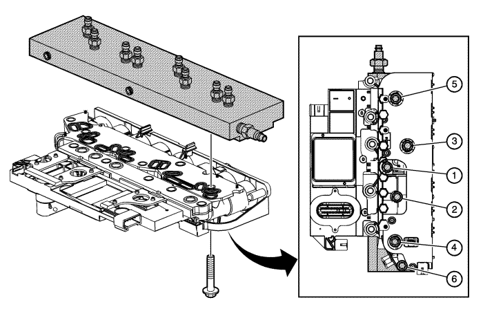
The purpose of this procedure is to test the control solenoid valve assembly solenoids for a stuck open or stuck closed condition, or a faulty transmission fluid pressure switch. DT-47825 test block is bolted to the control solenoid valve assembly on the valve body mounting surface. Pressurised air is passed into the aluminium test block, through the control solenoid valve assembly solenoid passage and back to the outlet port on the test block. A scan tool is used to command the solenoids ON and OFF. While observing the airflow, one can check the valve function. The recommended shop air pressure for this test is regulated to 90-100 psi.
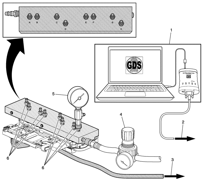
Caution: To avoid solenoid overheating and possible internal damage, do not continuously operate the solenoid for more than 2 minutes at a time. Drain the TCM of excess transmission fluid before attaching to test block and use caution when attaching air to test block air inlet.
Note: With the Vehicle in Service Mode and the engine OFF, the transmission control module will normally cycle some of the transmission solenoids On and Off to facilitate keeping the ports and solenoids clean and free of debris. This dither function is a normal activity and will cause the valves to cycle open and closed quickly when the TCM is powered up. This may cause some air to exit the ports where the pressure gauge is not connected as those solenoids cycle on and off.
Commanded State | Port On Test Block | Expected Result |
|---|---|---|
Vehicle OFF, no solenoids commanded and TCM not communicating | A, C, G | Air Flow |
Vehicle in Service Mode, no solenoids commanded and TCM communicating | A, B, C, D, E, F, G, H | No air flow from any port and no control solenoid valve assembly air leaks. This may take up to 30 seconds after vehicle is On. |
Shift Solenoid 1 | D | Air Flow |
Shift Solenoid 2 | H | Air Flow |
Pressure Control Solenoid 2 | C | Air Flow |
Pressure Control Solenoid 3 | G | Air Flow |
Pressure Control Solenoid 4 | B | Air Flow |
Pressure Control Solenoid 5 -- Command On | E | Air Flow |
Line Pressure Control Solenoid -- Command Increase/Decrease | A | 0 kPa = 0 psi 36.6 kPa = 20-30 psi 52.5 kPa = 32-56 psi 71.2 kPa = 44-74 psi 90 kPa = 70-90 psi 108 kPa = 90-100+psi Greater than 108 kPa = Scan tool displays Device Control Not Allowed |
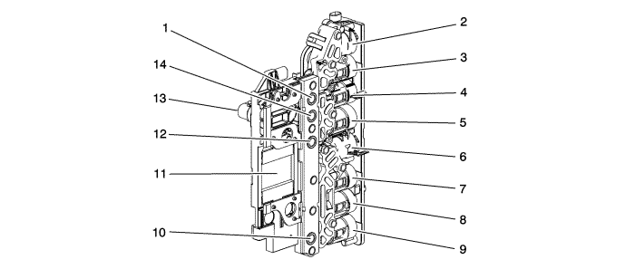
Callout | Component Name | DTC/Symptom Associated with Component |
|---|---|---|
1 | Transmission Fluid Pressure Switch 4 | P0756, P0757 |
2 | Shift Solenoid 2 | P0756, P0757, P0976, P0977, Possible Engine Unavailable |
3 | Pressure Control Solenoid 3 | P0796, P0797, P079A, P07A3, P0969, P0970, P0971 |
4 | Pressure Control Solenoid 6 -- Not Used | No DTCs or symptoms associated with this component |
5 | Pressure Control Solenoid 5 | P2728, P2729, P2730, Bump during engine start/stop transition |
6 | Shift Solenoid 1 | P0751, P0752, P0973, P0974, Possible Engine Unavailable |
7 | Pressure Control Solenoid 2 | P0776, P0777, P079B, P07A5, P0965, P0966, P0967 |
8 | Pressure Control Solenoid 4 | P079C, P07A7, P2714, P2715, P2719, P2720, P2721 |
9 | Line Pressure Control Solenoid | P0961, P0962, P0963 |
10 | Transmission Fluid Pressure Switch 1 | P0751, P0752, P2714, P2715 |
11 | Transmission Control Module | P0601-P0606, P060B, P062F, P0634, P0667, P0668, P0669, P06AC, P06AD, P06AE, P16F3, P16F7, P16F8, P179B |
12 | Transmission Fluid Pressure Switch 3 | P0751, P0752, P0776, P0777 |
13 | X1 20 Pin Connector | P2534, P2535 |
14 | Transmission Fluid Pressure Switch 5 | P0796, P0797 |
| ⇒ | If the Q8 control solenoid valve assembly fails any of the above tests, replace the Q8 control solenoid valve assembly. |
| ⇒ | If the Q8 control solenoid valve assembly passes the above tests, the problem is internal to the transmission. |
Perform the Diagnostic Repair Verification after completing the diagnostic procedure.
Control Module References for Control Solenoid Valve Assembly and Transmission Control Module replacement, programming, and setup.
| ©© Copyright Chevrolet. All rights reserved |


