Control Valve Body Cover Replacement
Removal Procedure
- Disconnect the negative battery cable. Refer to Battery Negative Cable Disconnection and Connection .
- Disable the high voltage system. Refer to High Voltage Disabling .
Danger: Do not use a service jack in locations other than those specified to lift this vehicle. Lifting the vehicle with a jack in those other locations could cause the vehicle to slip off the jack and roll; this could cause injury or death.
- Remove the drive motor battery radiator surge tank. Refer to Drive Motor Battery Radiator Surge Tank Replacement .
- Raise and support the vehicle. Refer to Lifting and Jacking the Vehicle .
- Drain the transmission. Refer to Transmission Fluid Replacement .
- Disconnect the transmission auxiliary fluid pump wire retainer from the upper retaining stud on the control valve body cover.
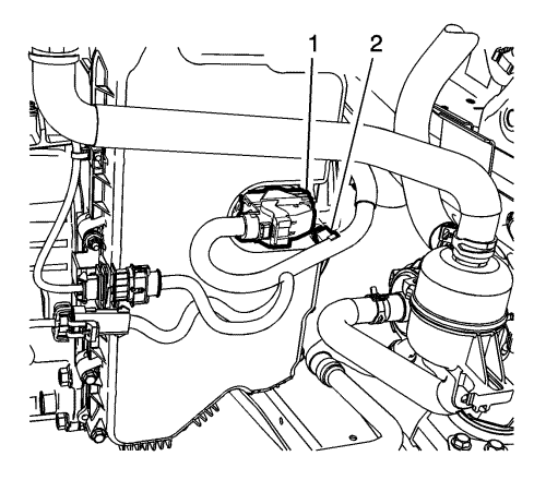
- Remove the wire harness retainer (2) from the control valve body cover stud, if fitted.
- Disconnect the control valve body transmission control module (TCM) electrical connector (1).
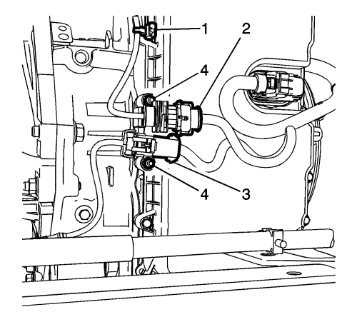
- Disconnect the heated oxygen sensor wire retainer (1) from the control valve body cover stud.
- Disconnect the heated oxygen sensor connectors (2, 3).
- Remove the connector bracket retaining fasteners (4).
- Position bracket away from the control valve body cover.
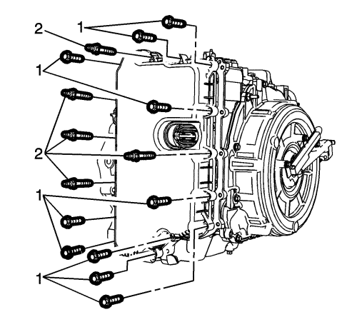
- Remove the 14 control valve body cover fasteners (1,2).
- Remove the control valve body cover.
- Remove the control valve body cover gasket, if necessary.
Caution: Support the control solenoid valve assembly around the connector when removing the seal. Excessive pulling force can damage the internal electrical connections.
- Remove the control valve body cover wiring connector hole seal, If necessary.
- Remove all traces of the old gasket material. Clean the transmission case and control valve body cover gasket surfaces.
Installation Procedure
- Install the control valve body cover wiring connector hole seal, if removed.
- Install the control valve body cover gasket to the control valve body cover, if removed.
- Install the control valve body cover.
Caution: Refer to Fastener Caution in the Preface section.
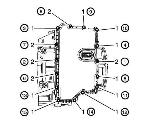
Note: Install all control valve body cover bolts and studs by hand then torque all bolts and studs in the sequence shown.
- Tighten the 14 control valve body cover fasteners in the sequence shown to 9 N·m (80 lb in).
- Connect the control valve body TCM electrical connector (1).
- Install the wire harness retainer (2) to the control valve body cover stud.
- Connect the transmission auxiliary fluid pump wire retainer to the upper retaining stud on the control valve body cover.
- Connect the heated oxygen sensor wire retainer (1) to the control valve body cover stud.
- Position bracket on the control valve body cover studs.
- Install the connector bracket retaining fasteners (4), Then tighten the fasteners (4) to 9 N·m (80 lb in).
- Connect the heated oxygen sensor connectors (2, 3).
- Lower the vehicle.
- Fill the transmission. Refer to Transmission Fluid Replacement .
- Install the drive motor battery radiator surge tank. Refer to Drive Motor Battery Radiator Surge Tank Replacement .
- Enable the high voltage system. Refer to High Voltage Enabling .
- Connect the negative battery cable. Refer to Battery Negative Cable Disconnection and Connection .
- Check for leaks.
| © Copyright Chevrolet. All rights reserved |


