Cylinder Head Replacement
Special Tools
| • | EN-470-B Angular Torque Wrench . |
For equivalent regional tools, refer to Special Tools
Removal Procedure
Danger: Always perform the High Voltage Disabling procedure prior to servicing any High Voltage component or connection. Personal Protection Equipment (PPE) and proper procedures must be followed.
The High Voltage Disabling procedure will perform the following tasks:
| • | Identify how to disable high voltage. |
| • | Identify how to test for the presence of high voltage. |
| • | Identify condition under which high voltage is always present and personal protection equipment (PPE) and proper procedures must be followed. |
- Disable the high voltage system. Refer to High Voltage Disabling
- Remove the camshaft cover. Refer to Camshaft Cover Replacement
- Remove the exhaust manifold. Refer to Exhaust Manifold with Catalytic Converter Replacement
- Remove the Inlet manifold. Refer to Inlet Manifold Replacement
- Install engine support fixture. Refer to Engine Support Fixture
- Remove the Water Pump. Refer to Water Pump Replacement
- Remove the water outlet. Refer to Water Outlet Replacement
- Remove the Camshaft Position Actuator Solenoid Valve inlet and exhaust. Refer to
Camshaft Position Actuator Solenoid Valve Replacement : Exhaust → Intake
- Remove the Camshaft Position Sensor Exhaust only. Refer to
Camshaft Position Sensor Replacement : Intake → Exhaust
- Adjust the engine to TDC. Refer to Camshaft Timing Chain Inspection
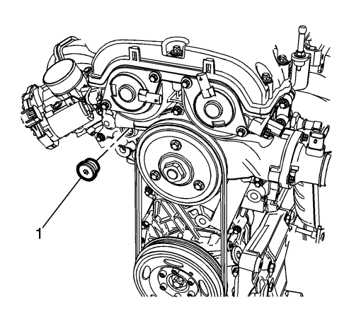
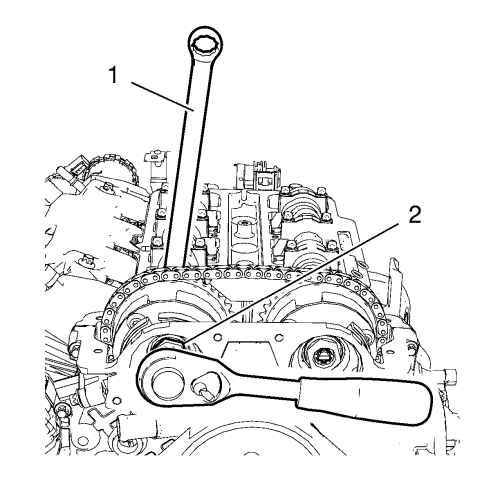
- Remove the timing chain tensioner plug (1) from the engine front cover.
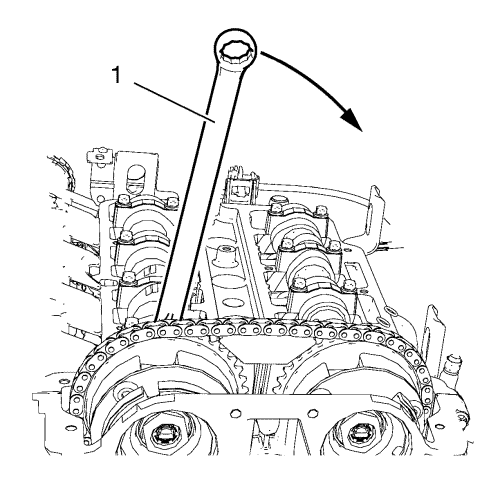
- Install a wrench (1) on the cast hexagonal portion of the inlet camshaft, rotate the camshaft toward the exhaust camshaft in order to apply tension.
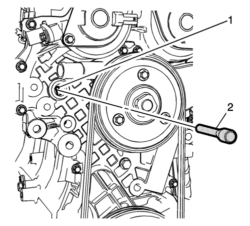
- Install EN-955 Locking Pin (2) to the timing chain tensioner bore (1).
- Remove the wrench from inlet camshaft.
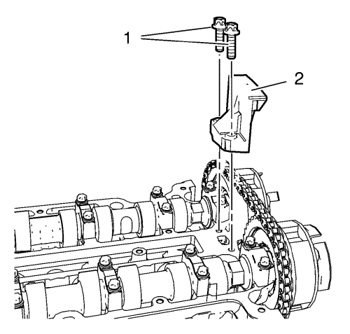
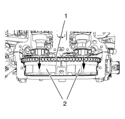
- Remove the 2 upper timing chain guide bolts (1).
- Remove the upper timing chain guide (2).
- Loosen the inlet camshaft sprocket bolt (2) while holding up the hexagon of the inlet camshaft with a wrench (1).
- Loosen the exhaust camshaft sprocket bolt while holding up the hexagon of the exhaust camshaft with a wrench.
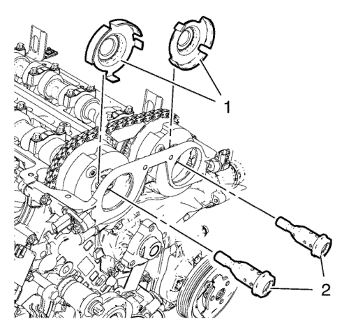
- Remove the camshaft sprocket bolts (2) and the camshaft position exciter wheels (1).
- Remove the camshaft sprockets (2) and timing chain (1) as one unit.
- Disconnect electrical connectors as necessary.
- Reposition electrical harness aside.
- Allow the camshaft sprockets (2) and timing chain (1) rest on the front cover Do NOT remove sprockets or chain.
- Place a floor jack with block of wood under the oil sump.
- Remove engine support fixture. Refer Engine Support Fixture
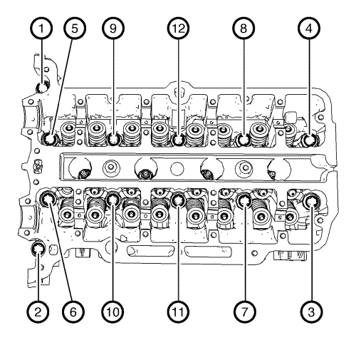
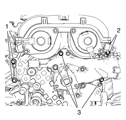
- Loosen the 12 cylinder head bolts in the sequence as shown above. Use the following procedure:
| • | First pass: Loosen the cylinder head bolts 90 degrees. |
| • | Final pass: Loosen the cylinder head bolts 180 degrees. |
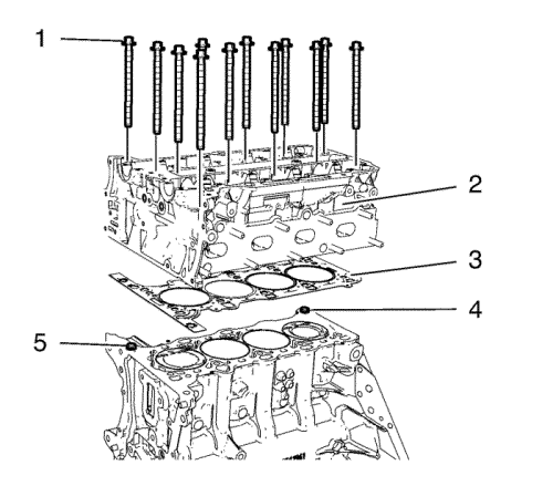
Note: Do not damage the guide sleeves (4) and (5).
- Remove the cylinder head bolts (1).
- With the aid of helper, lift the timing chain side of the cylinder head assembly slightly in direction of the transmission.
- Remove the cylinder head (2).
- Remove the cylinder head gasket (3) and discard the gasket.
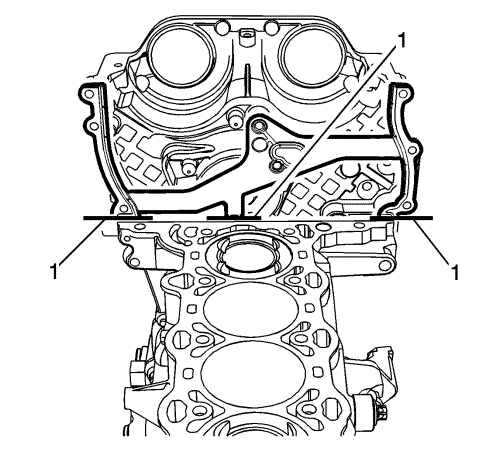
- With the cylinder head out of vehicle bend the top third of the engine front cover gasket (1) back and forth until snaps off at the breaking point.
- Transfer parts as necessary.
- Clean and inspect the cylinder head. Refer to Cylinder Head Cleaning and Inspection
- For disassembly of the cylinder head. Refer to Cylinder Head Disassemble
Installation Procedure
- For disassembly of the cylinder head. Refer to Cylinder Head Assemble
- Clean sealing surfaces of engine front cover and engine block from grease and old gasket material.
Note: The engine front cover gasket comes as a complete unit.
- Before installation the of the new front cover gasket, bend the top third of the engine front cover gasket (1) back and forth until snaps off at the breaking point.
- Install the engine front cover gasket (1) to ensure for a proper fit and alignment.
- Clean the surface of the cylinder head and engine front cover.
- Install the cylinder head gasket to engine block.
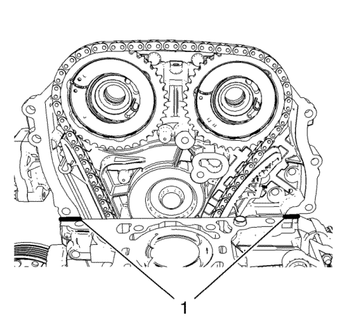
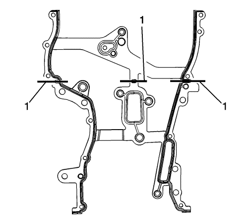
- Apply a 2 mm (0.0787 in) bead of RTV sealant to the areas shown (1).
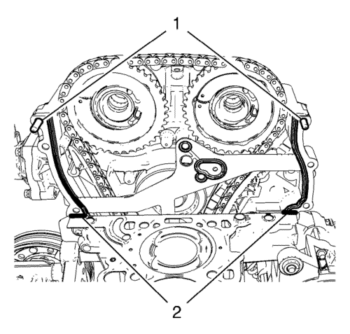
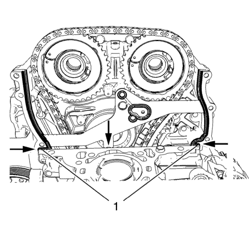
- Install engine front cover bolts (1) in order to guide the NEW upper engine front cover gasket.
- Apply a 2 mm (0.0787 in) bead of RTV sealant to the areas shown (2).
- Ensure the guide sleeves are in place (4) and (5) before installing the cylinder head.
- Install a NEW cylinder head gasket (3). The marking "Top" should point to the cylinder head.
- Install the cylinder head (2).
- Install the cylinder head bolts (1) and hand tighten only.
- Adjust the cylinder head to the engine front cover. Use a rubber mallet.
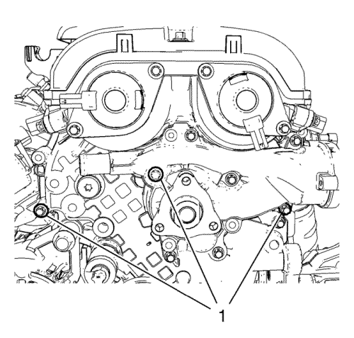
- Position the engine front cover to cylinder head by installing 3 bolts (1).
Caution: Refer to Fastener Caution in the Preface section.
- Tighten the 3 bolts (1) to 8 N·m (71 lb in).
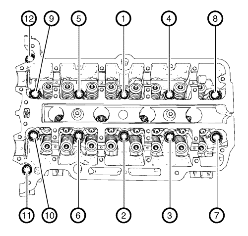
- Using a EN-470-B angular torque wench tighten the cylinder head bolts in the sequence as shown above. Tighten the cylinder head bolts to 25 N·m (18 lb ft) plus 180 degrees.
- Loosen the bolts from engine front cover (1).
- Install the remaining bolts to engine front cover and water pump.
- Tighten the engine front cover bolts (1) and (2) to 8 N·m (71 lb in).
- Tighten the water pump bolts (3) to 8 N·m (71 lb in).
- Install the water pump pulley. Refer to Water Pump Pulley Replacement
- Install engine mount bracket. Refer to Engine Mount Bracket Replacement - Right Side
- Install the engine mount. Refer to Engine Mount Replacement - Right Side
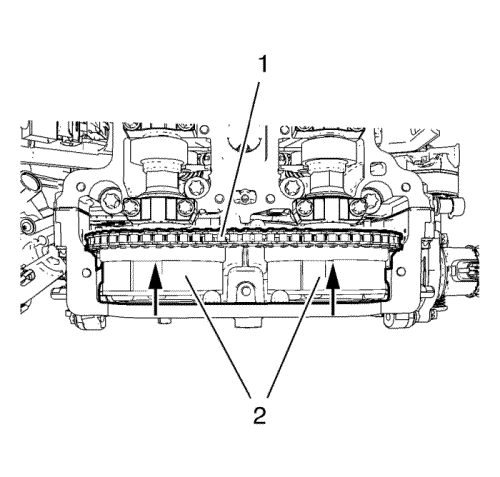
- Install the camshaft sprockets (2) and timing chain (1) as one unit.
- Install the camshaft position exciter wheels (1).
- Install the camshaft sprocket bolts (2) and tighten to 50 N·m (37 lb ft) plus 45 + 15 degrees.
- Remove the EN-955 locking pin .
- Adjust the camshaft timing chain. Refer to Camshaft Timing Chain Inspection
- Install the upper timing chain guide (2).
- Install the upper timing chain guide bolts (1) and tighten to 8 N·m (71 lb in).
- Install the timing chain tensioner plug and tighten to 50 N·m (37 lb ft).
- Install the Camshaft Position Actuator Solenoid Valve inlet and exhaust. Refer to
Camshaft Position Actuator Solenoid Valve Replacement : Exhaust → Intake
- Install the Camshaft Position Sensor Exhaust only. Refer to
Camshaft Position Sensor Replacement : Intake → Exhaust
- Install the camshaft cover. Refer to Camshaft Cover Replacement
- Install the exhaust manifold. Refer to Exhaust Manifold with Catalytic Converter Replacement
- Install Inlet manifold. Refer to Inlet Manifold Replacement
- Install the water outlet. Refer to Water Outlet Replacement
- Fill coolant fluid. Refer to Cooling System Draining and Filling
- Enable the high voltage system. Refer to High Voltage Enabling
- Test the vehicle using the following procedure:
| • | Crank the engine several times. Listen for any unusual noises or evidence that parts are binding. |
| • | Start the engine and listen for unusual noises. |
| • | Check the vehicle oil pressure gauge or light and confirm that the engine has acceptable oil pressure. |
| • | Run the engine speed at about 1,000 RPM until the engine has reached normal operating temperature. |
| • | Listen for sticking lifter and other unusual noises. |
| • | Inspect for fuel, oil and/or coolant leaks while the engine is running. |
- Road test the vehicle for normal operation.
- Inspect for coolant, oil, gas or exhaust leaks.
| © Copyright Chevrolet. All rights reserved |


