Electronic Component Description
Electronic Components
The 4ET50 transmission contains the electronic components listed below:
| • | A/Trans Manual Shaft Position Switch Assembly |
| • | A/Trans Output Speed Sensor Assembly |
| • | Control solenoid valve assembly |
| • | Electric drive motor/generator assembly - unit A |
| • | Electric drive motor/generator assembly - unit B |
| • | Electric auxiliary pump drive motor assembly |
This transmission operates in 4 electronically variable transmission modes. High voltage three phase cables connect the 2 motor/generators and the electric auxiliary pump drive motor assembly, to the drive motor generator control module. The high voltage electric auxiliary pump drive provides transmission fluid pressure during engine-off operation.
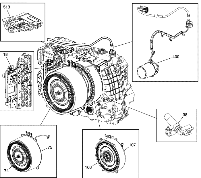
Electronic Components
|
|---|
| (18) | Control Solenoid Valve Assembly |
| (38) | A/Trans Output Speed Sensor Assembly, internal to transmission |
| (74) | Drive Motor/Generator Rotor Assembly -Unit B |
| (75) | Drive Motor/Generator Stator Assembly -Unit B |
| (107) | Generator/Drive Motor Stator Assembly -Unit A |
| (108) | Generator/Drive Motor Rotor Assembly -Unit A |
| (400) | Electric Auxiliary Pump Drive Motor Assembly |
| (513) | A/Trans Manual Shaft Position Switch Assembly |
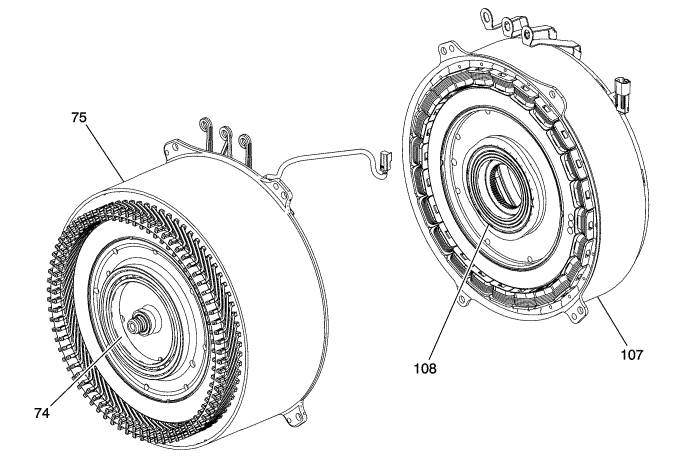
Drive Motor/Generator Assemblies
|
|---|
| (74) | Drive Motor/Generator Rotor Assembly -Unit B |
| (75) | Drive Motor/Generator Stator Assembly -Unit B |
| (107) | Generator/Drive Motor Stator Assembly -Unit A |
| (108) | Generator/Drive Motor Rotor Assembly -Unit A |
The drive motor generator power inverter module assembly controls the three permanent magnet 3-phase electric motors that are internal to the transmission, and perform the following functions:
| • | Torque for vehicle propulsion |
| • | Transmission fluid pressure during engine-off operation |
The Drive Motor/Generator Description
Drive motor/generator assembly - Unit A is a generator referred to as Motor 1 on the scan tool and consists of a permanent magnet rotor with a concentrated wound stator capable of producing 58 kW of peak electrical energy and 185 N·m (136 lb ft) of torque at 300V.
Drive motor/generator assembly - Unit B is a traction motor referred to as Motor 2 on the scan tool and consists of a permanent magnet rotor with a bar wound stator capable of producing 116 kW of peak electrical energy and 370 N·m (273 lb ft) of torque at 300V.
Both are actively cooled via transmission fluid. The drive motor/generator assembly - unit A is used to start the engine and maintain charge to the hybrid battery. The drive motor/generator assembly - unit B propels the vehicle. Motor speeds are controlled and monitored by resolver-type position sensors. The drive motor generator position sensors are monitored by the motor control modules. The motor control modules monitor the angular position, speed and direction of the drive motor generator based upon the signals of these position sensors. The position sensor, or resolver, contains a drive coil, 2 driven coils and an irregular shaped metallic rotor. The metallic rotor is mechanically attached to the shaft of the drive motor generator. At ignition ON, the motor control module outputs a 5 volt ac, 10 kHz excitation signal to the drive coil. The drive coil excitation signal creates a magnetic field surrounding the 2 driven coils and the irregular shaped rotor. The motor control module then monitors the 2 driven coil circuits for a return signal. The position of the irregular shaped metallic rotor causes the magnetically-induced return signals of the driven coils to vary in size and shape. A comparison of the 2 driven coils signals allows the motor control module to determine the exact angle, speed and direction of the drive motor generator. For more information on the drive motor function and system interaction refer to Drive Motor Generator Power Inverter Module Description and Operation .
Electric Auxiliary Pump Drive Motor Assembly
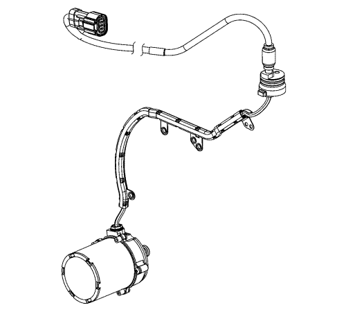
The electric auxiliary pump drive motor assembly is driven by 300V alternating current which is controlled by the drive motor/generator power inverter module assembly. The purpose of the auxiliary pump drive motor is to supply oil pressure to the transmission for lubrication, cooling and clutch application during vehicle propulsion when the engine is off and the main transmission pump is not operating. The auxiliary pump drive motor is commanded on when propulsion is active and the internal combustion engine is Off.
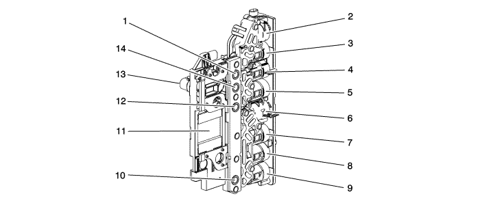
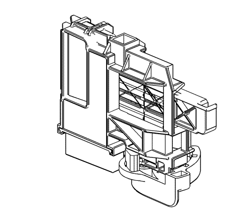
Control Solenoid Valve Assembly
|
|---|
| (1) | Transmission Fluid Pressure Switch 4 |
| (2) | Shift Solenoid 2 |
| (3) | Pressure Control Solenoid 3 |
| (4) | Pressure Control Solenoid 6 - Not Used |
| (5) | Pressure Control Solenoid 5 |
| (6) | Shift Solenoid 1 |
| (7) | Pressure Control Solenoid 2 |
| (8) | Pressure Control Solenoid 4 |
| (9) | Line Pressure Control Solenoid |
| (10) | Transmission Fluid Pressure Switch 1 |
| (11) | Transmission Control Module |
| (12) | Transmission Fluid Pressure Switch 3 |
| (13) | X1 20 Pin Connector |
| (14) | Transmission Fluid Pressure Switch 5 |
The control solenoid valve assembly contains the following components:
| • | Transmission control module |
| • | Clutch pressure control solenoids |
| • | Line pressure control solenoid |
| • | Transmission fluid temperature sensor |
| • | Transmission fluid pressure switches |
These components are not serviced separately. The control assembly utilises a lead-frame system to connect these components electrically to the transmission control module. No wires are used for these components. The control solenoid assembly bolts directly to the valve body assembly within the transmission. The control solenoid assembly X1 connector connects to the engine harness.
A/Trans Manual Shift Shaft Position Switch Assembly
The A/Trans manual shift shaft position switch assembly is a dual sliding hall-effect switch attached to the control valve body within the transmission. The 9 outputs from the switch indicate which position is selected by the transmission manual shaft. Four outputs (A, B, C, P), are range selection inputs to the transmission control module. The five (R1, R2, D1, D2, S) direction selection inputs to the hybrid powertrain control module through the transmission X176 24-way connector. The input voltage at the modules is high when the switch is open and low when the switch is closed. The state of each input is displayed on the scan tool as Internal Mode Switch Range and Internal Mode Switch 2. The Internal Mode Switch Range input parameters represented are transmission range signal A, signal B, signal C and signal P. The Internal Mode Switch 2 parameters represented are transmission direction signal R1, signal R2, signal D1, signal D2 and signal S.
Output Speed Sensor (OSS)
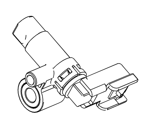
The output speed sensor assembly has 2 internal hall-effect type sensors, and is capable of sensing both speed and direction. The output speed sensor mounts to the A/Trans case assembly and is connected to the control solenoid assembly through a wire harness and connector. The sensor faces the front differential drive pinion (w/transfer gear) gear assembly machined teeth surface. The sensor receives 8.3-9.3 volts on the OSS supply voltage circuit from the transmission control module. As the output shaft rotates, the sensor produces a signal frequency based on the machined surface of the output shaft.
The 2 sensor elements in the output speed sensor assembly are spaced approximately 1/2 a tooth apart.
| • | When the vehicle is moving in a forward direction, sensor A detects a particular tooth before sensor B. |
| • | When the vehicle is moving in a reverse direction, sensor B detects a particular tooth before sensor A. |
The electronics in the sensor combine the 2 signals and send a signal with a different pulse width. This signal is interpreted by the transmission control module for speed and direction and is transmitted through the serial data circuits to the engine control module and the hybrid powertrain control module 1. The engine control module, hybrid powertrain control module 1, and transmission control module compare the output speed sensor signal with the anti-lock brake system wheel speed sensor signal. The hybrid powertrain control module 1 also compares the output shaft direction with the drive motor 1 and drive motor 2 direction.
| ©© Copyright Chevrolet. All rights reserved |


