Volt |
||||||||
|
|
|
|||||||
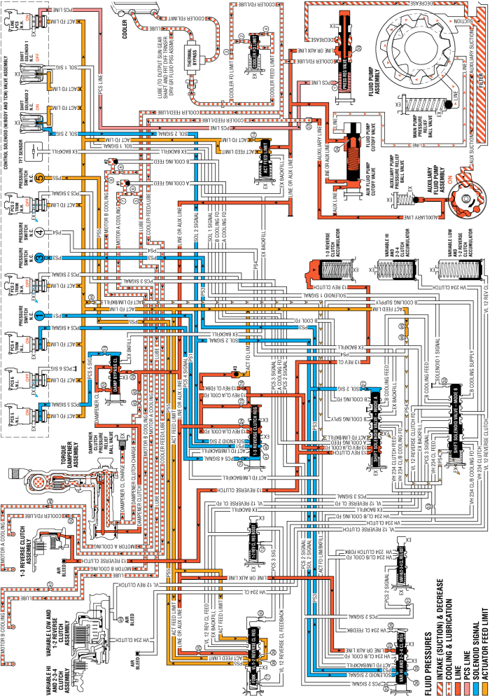
When the vehicle is operating with the internal combustion engine OFF and auxiliary fluid pump ON, and the HPCM determines that vehicle operating conditions (low state of battery charge) are appropriate for starting the internal combustion engine (ICE), it commands the following changes to the transmission's hydraulic and electrical systems.
Note: The illustration shown depicts an Engine Start event that occurs during vehicle operation in Park. However, Engine Start can occur in any transmission operating range.
The PC solenoid 5 is energised (ON) allowing actuator feed limit fluid to enter the PCS 5 signal circuit. PCS 5 signal fluid is then routed through orifice #13 to the damper bypass clutch valve.
PCS 5 signal fluid, at the damper bypass clutch valve, opposes damper bypass clutch valve spring force and orificed damper clutch fluid pressure to regulate line or auxiliary line pressure into the damper clutch circuit. Damper clutch fluid is routed to the torque damper clutch.
A feed hole in the input shaft allows fluid to enter the torque damper assembly behind the torque damper clutch piston. Damper clutch fluid pressure moves the damper clutch piston against spring force to apply the damper clutch plates. When fully applied, the damper clutch apply plate, the damper clutch plates, and the damper clutch plate assemblies are locked together, forming a direct mechanical connection between the engine flywheel and the transmission input shaft. With the engine flywheel and transmission input shaft locked together, the HPCM is able to use the generator/drive motor - unit A (107, 108) to start the ICE. The torque damper clutch may be applied in any range when the vehicle is operating with the internal combustion engine OFF.
The PC solenoid 4 is energised (ON) allowing actuator feed limit fluid to enter the PCS 4 signal circuit. PCS 4 signal fluid is then routed through orifice #18 to the 1-3 reverse clutch regulator valve.
PCS 4 signal fluid, at the 1-3 reverse clutch regulator valve, opposes 1-3 reverse clutch regulator valve spring force and 13 reverse clutch feedback fluid pressure to regulate line or auxiliary line pressure into the 13 reverse clutch/A cooling feed circuit.
13 reverse clutch feedback fluid unseats the #3 ball check valve, allowing excess pressure to pass into the actuator feed limit circuit. This helps to control clutch apply fluid pressure and clutch apply feel.
13 reverse clutch/A cooling feed fluid passes through the shift solenoid valve - mode A and enters the 13 reverse clutch circuit.
13 reverse clutch fluid passes through the case and the transmission fluid pump cover into the 1-3 reverse clutch housing and moves the 1-3 reverse clutch piston against spring force to apply the 1-3 reverse clutch plates.
Solenoid 2 signal fluid passes through the 1-3 reverse clutch regulator valve into the PS1 fluid passage. PS1 fluid opens the normally closed #1 pressure switch, signalling the TCM that the transmission is in Engine Start.
13 reverse clutch fluid is also sent to the 1-3 reverse clutch accumulator assembly. 13 reverse clutch fluid moves the 1-3 reverse clutch accumulator piston against accumulator spring force to cushion the apply of the 1-3 reverse clutch assembly.
| © Copyright Chevrolet. All rights reserved |


