Volt |
||||||||
|
|
|
|||||||
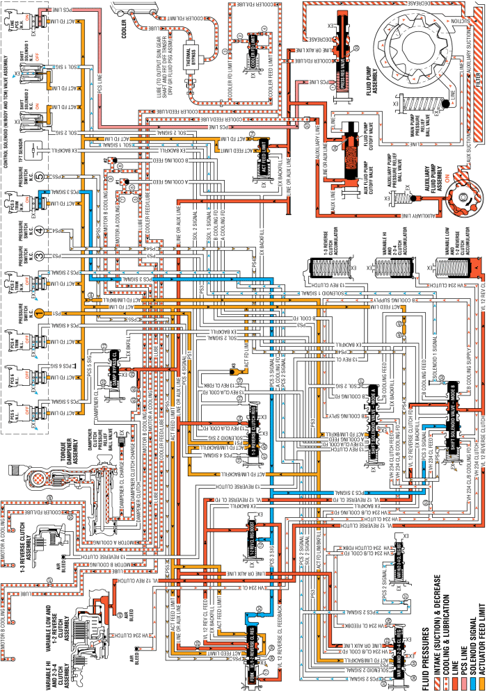
When the transmission is operating in Reverse - Output Split (R) and the internal combustion engine is OFF, and the HPCM determines that operating conditions are appropriate, Reverse - Series Mode is commanded and the following changes occur in the transmission's hydraulic and electrical systems.
The PC solenoid 3 is energised (ON) allowing actuator feed limit fluid to enter the PCS 3 signal circuit. PCS 3 signal fluid is then routed through orifice #30 to the variable low and 1-2 reverse clutch regulator valve; through orifice #12 to the variable low and 1-2 reverse clutch boost valve; and to the shift solenoid valve - mode B.
The shift solenoid 1 is commanded OFF, allowing solenoid 1 signal fluid to exhaust. When solenoid 1 signal fluid exhausts, the shift solenoid valve - mode B moves to the released position.
PCS 3 signal fluid, at the variable low and 1-2 reverse clutch regulator valve, opposes variable low and 1-2 reverse clutch regulator valve spring force and VL 12 reverse clutch feedback fluid pressure to regulate line or auxiliary line pressure into the VL 12 reverse clutch feed circuit.
PCS 3 signal fluid pressure acts on a differential area of the variable low and 1-2 reverse clutch boost valve, moving the valve against variable low and 1-2 reverse clutch boost valve spring force to regulate VL 12 reverse clutch feed fluid into the VL 12 reverse clutch feedback circuit. As PCS 3 signal fluid pressure is increased to a given value, the variable low and 1-2 reverse clutch boost valve opens the VL 1-2 reverse clutch feedback circuit to exhaust. This results in the variable low and 1-2 reverse clutch regulator valve moving to the full feed position, sending full VL 12 reverse clutch feed pressure (full line pressure) to the variable low and 1-2 reverse clutch.
VL 12 reverse clutch feed fluid is routed to the shift solenoid valve - mode B, where it passes through the valve into the VL 12 reverse clutch circuit.
VL 12 reverse clutch fluid pressure enters the case assembly behind the variable low and 1-2 reverse clutch piston and moves the piston against spring force to apply the variable low and 1-2 reverse clutch plates.
The PC solenoid 2 is commanded OFF, allowing PCS 2 signal fluid to exhaust from the variable hi and 2-3-4 clutch regulator valve and the variable hi and 2-3-4 clutch boost valve.
VH 234 clutch fluid pressure is exhausted from the case assembly, allowing variable hi and 2-3-4 clutch spring force to move the variable hi and 2-3-4 clutch piston and release the variable hi and 2-3-4 clutch plates.
Exhausting VH 234 clutch fluid pressure passes through the shift solenoid valve - mode B into the 234 clutch feed circuit.
Exhausting 234 clutch feed fluid pressure passes through the shift solenoid valve - mode A into the VH 234 clutch/B cooling feed circuit.
Variable hi and 2-3-4 clutch regulator valve spring force moves the variable hi and 2-3-4 clutch regulator valve to the released position, allowing VH 234 clutch/B cooling feed fluid pressure to exhaust.
VL 12 reverse clutch fluid is also sent to the variable low and 1-2 reverse clutch accumulator assembly. VL 12 reverse clutch fluid moves the variable low and 1-2 reverse clutch accumulator piston against accumulator spring force to cushion the apply of the variable low and 1-2 reverse clutch assembly.
VH 234 clutch fluid also exhausts from the variable hi and 2-3-4 clutch accumulator assembly. Accumulator spring force moves the variable hi and 2-3-4 clutch accumulator piston to the released position.

| © Copyright Chevrolet. All rights reserved |