Volt |
||||||||
|
|
|
|||||||
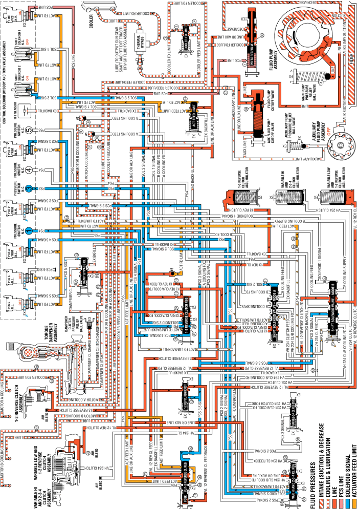
When the gear selector lever is moved to the Drive (D) position from the Neutral (N) position, and the HPCM determines that operating conditions are appropriate, the internal combustion engine (ICE) is started, the auxiliary fluid pump is turned OFF, and the main fluid pump provides hydraulic fluid pressure (refer to Engine Start ). After Engine Start, the following changes would occur to the transmission's hydraulic and electrical systems in order to start the vehicle moving from a stopped position.
The 1-3 reverse clutch is applied for Engine Start, and remains applied for Reverse - Series Mode (Engine ON).
The PC solenoid 4 is energised (ON) allowing actuator feed limit fluid to enter the PCS 4 signal circuit. PCS 4 signal fluid is then routed through orifice #18 to the 1-3 reverse clutch regulator valve.
The shift solenoid 2 is energised (ON) allowing actuator feed limit fluid to enter the solenoid 2 signal fluid circuit. Solenoid 2 signal fluid is routed through orifice #21 to the shift solenoid valve - mode A. Solenoid 2 signal fluid is also routed to the variable hi and 2-3-4 clutch regulator valve, and to the 1-3 reverse clutch regulator valve.
PCS 4 signal fluid, at the 1-3 reverse clutch regulator valve, opposes 1-3 reverse clutch regulator valve spring force and 13 reverse clutch feedback fluid pressure to regulate line or auxiliary line pressure into the 13 reverse clutch/A cooling feed circuit.
13 reverse clutch feedback fluid unseats the #3 ball check valve, allowing excess pressure to pass into the actuator feed limit circuit. This helps to control clutch apply fluid pressure and clutch apply feel.
13 reverse clutch/A cooling feed fluid passes through the shift solenoid valve - mode A and enters the 13 reverse clutch circuit.
13 reverse clutch fluid passes through the case and the transmission fluid pump cover into the 1-3 reverse clutch housing and moves the 1-3 reverse clutch piston against spring force to apply the 1-3 reverse clutch plates.
Solenoid 2 signal fluid passes through the 1-3 reverse clutch regulator valve into the PS1 fluid passage. PS1 fluid opens the normally closed #1 pressure switch, signalling the TCM that the transmission is in Drive - Series Mode.
Solenoid 2 signal fluid passes through the variable hi and 2-3-4 clutch regulator valve into the PS3 fluid passage. PS3 fluid opens the normally closed #3 pressure switch, signalling the TCM that the transmission is in Drive - Series Mode.
The PC solenoid 5 is de-energised (OFF) allowing PCS 5 signal fluid to exhaust from the damper bypass clutch valve.
Damper clutch fluid exhausts from the torque damper clutch assembly to the damper bypass clutch valve allowing the torque damper clutch to release.
Damper bypass clutch valve spring force moves the damper bypass clutch valve to the released position, allowing damper clutch fluid pressure to exhaust through the valve into the exhaust backfill circuit.
Damper clutch fluid pressure in the exhaust backfill circuit exhausts at the TFT sensor.
With the exception of the switch to line fluid pressure from the main fluid pump assembly, no other changes occur to the variable low and 1-2 reverse clutch fluid circuit and the variable low and 1-2 reverse clutch remains applied.
13 reverse clutch fluid is also sent to the 1-3 reverse clutch accumulator assembly. 13 reverse clutch fluid moves the 1-3 reverse clutch accumulator piston against accumulator spring force to cushion the apply of the 1-3 reverse clutch assembly
VL 12 reverse clutch fluid is also sent to the variable low and 1-2 reverse clutch accumulator assembly. VL 12 reverse clutch fluid moves the variable low and 1-2 reverse clutch accumulator piston against accumulator spring force to cushion the apply of the variable low and 1-2 reverse clutch assembly.
| © Copyright Chevrolet. All rights reserved |


