Volt |
||||||||
|
|
|
|||||||
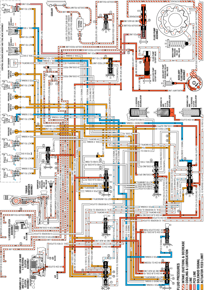
When the gear selector lever is moved to the Drive (D) position from the Neutral (N) position, and the internal combustion engine (ICE) is OFF, the following changes occur in the transmission's hydraulic and electrical systems in order to start the vehicle moving from a stopped position.
The PC solenoid 2 is energised (ON) allowing actuator feed limit fluid to enter the PCS 2 signal circuit. PCS 2 signal fluid is then routed through orifice #20 to the variable hi and 2-3-4 clutch regulator valve.
The shift solenoid 1 is energised (ON) allowing actuator feed limit fluid to enter the solenoid 1 signal fluid circuit. Solenoid 1 signal fluid is then routed through orifice #32 to the shift solenoid valve - mode B.
PCS 2 signal fluid, at the variable hi and 2-3-4 clutch regulator valve, opposes variable hi and 2-3-4 clutch regulator valve spring force and VH 234 clutch feedback fluid pressure to regulate line or auxiliary line pressure into the VH 234 clutch/B cooling feed circuit.
PCS 2 signal fluid pressure acts on a differential area of the variable hi and 2-3-4 clutch boost valve, moving the valve against variable hi and 2-3-4 clutch boost valve spring force to regulate VH 234 clutch/B cooling feed fluid into the VH 234 clutch feedback circuit. As PCS 2 signal fluid pressure is increased to a given value, the variable hi and 2-3-4 clutch boost valve opens the VH 234 clutch feedback circuit to exhaust. This results in the variable hi and 2-3-4 clutch regulator valve moving to the full feed position, sending full VH 234 clutch feed pressure (full line pressure) to the variable hi and 2-3-4 clutch.
VH 234 clutch/B cooling feed fluid passes through the shift solenoid valve - mode A into the VH 234 clutch feed fluid circuit and is routed to the shift solenoid valve - mode B.
VH 234 clutch feed fluid passes through the shift solenoid valve - mode B into the VH 234 clutch circuit and is routed to the variable hi and 2-3-4 clutch assembly.
VH 234 clutch fluid is directed to the variable hi and 2-3-4 clutch piston to apply the variable hi and 2-3-4 clutch plates and achieve Reverse - Output Split.
The PC solenoid 3 is de-energised (OFF) allowing PCS 3 signal fluid to exhaust from the variable low and 1-2 reverse clutch regulator valve; the variable low and 1-2 reverse clutch boost valve; and the shift solenoid valve -mode B.
VL 12 reverse clutch fluid exhausts from the variable low and 1-2 reverse clutch to the shift solenoid valve - mode B allowing the variable low and 1-2 reverse clutch to release.
VL 12 reverse clutch fluid passes through the shift solenoid valve - mode B and into the exhaust backfill fluid circuit.
Variable low and 1-2 reverse clutch boost valve spring force moves the variable low and 1-2 reverse clutch boost valve to the released position, allowing VL 12 reverse clutch feedback fluid pressure to exhaust into the VL 12 reverse clutch feed circuit.
Variable low and 1-2 reverse clutch regulator valve spring force moves the variable low and 1-2 reverse clutch regulator valve to the released position, allowing VL 12 reverse clutch feed fluid pressure to exhaust through the valve into the exhaust backfill circuit.
VL 12 reverse clutch fluid pressure in the exhaust backfill circuit exhausts at the TFT sensor.
VH 234 clutch fluid is also sent to the variable hi and 2-3-4 clutch accumulator assembly. VH 234 clutch fluid moves the variable hi and 2-3-4 clutch accumulator piston against accumulator spring force to cushion the application of the variable hi and 2-3-4 clutch assembly.
VL 12 reverse clutch fluid also exhausts from the variable low and 1-2 reverse clutch accumulator assembly. Accumulator spring force moves the variable low and 1-2 reverse clutch accumulator piston to the released position.
| © Copyright Chevrolet. All rights reserved |


