Body Side Inner Panel Sectioning
Danger: Always perform the High Voltage Disabling procedure prior to servicing any High Voltage component or connection. Personal Protection Equipment (PPE) and proper procedures must be followed.
The High Voltage Disabling procedure will perform the following tasks:
| • | Identify how to disable high voltage. |
| • | Identify how to test for the presence of high voltage. |
| • | Identify condition under which high voltage is always present and personal protection equipment (PPE) and proper procedures must be followed. |
| • | Safety glasses with appropriate side shields when within 15 meters (50 feet) of the vehicle, either indoors or outdoors. |
| • | Certified and up-to-date Class "0" Insulation gloves rated at 1000V with leather protectors. |
| - | Visually and functionally inspect the gloves before use. |
| - | Wear the Insulation gloves with leather protectors at all times when working with the high voltage battery assembly, whether the system is energised or not. |
Removal Procedure
Warning : Refer to Approved Equipment for Collision Repair Warning in the Preface section.
Warning : Refer to Collision Sectioning Warning in the Preface section.
Warning : Refer to Glass and Sheet Metal Handling Warning in the Preface section.
- Disable the SIR system. Refer to SIR Disabling and Enabling .
- Inspect the high voltage system. Refer to High Voltage System Inspection .
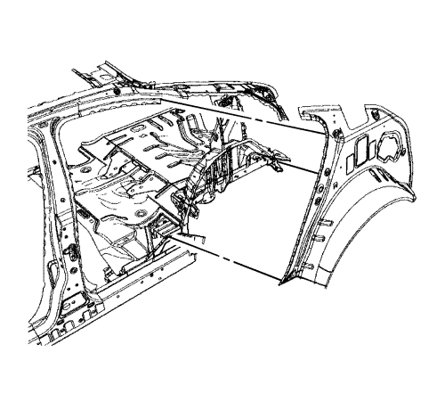
- Remove all related panels and components.
- Visually inspect the damage. Repair as much of the damage as possible.
- Remove the sealers and anti-corrosion materials from the repair area, as necessary. Refer to Anti-Corrosion Treatment and Repair .
- Section quarter outer panel. Refer to Quarter Outer Panel Sectioning .
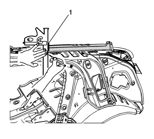
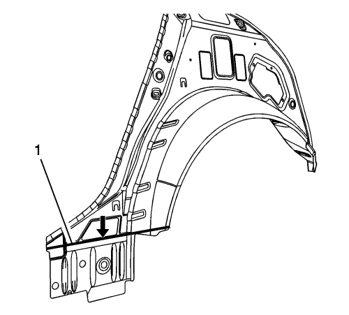
- Create section line (1) on the quarter panel extension.
- Cut the panel at the section joint (1).
Note: use a heat gun to facilitate removal in areas where structural adhesive is present.
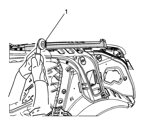
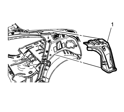
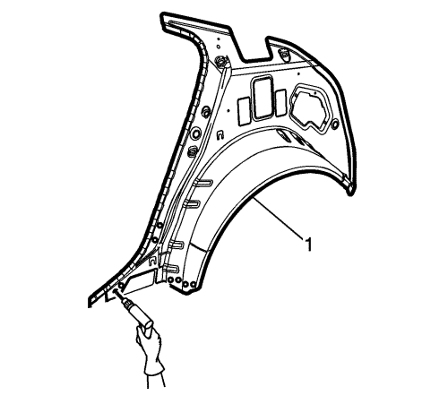
- Remove quarter panel extension (1).
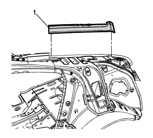
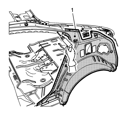
- Locate and drill factory welds on the body lock pillar upper reinforcement (1). Note the number and location of welds for installation.
- Remove reinforcement (1) from quarter inner panel.
Note : Do not damage any other panels or reinforcements.
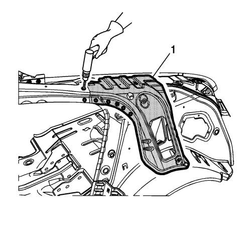
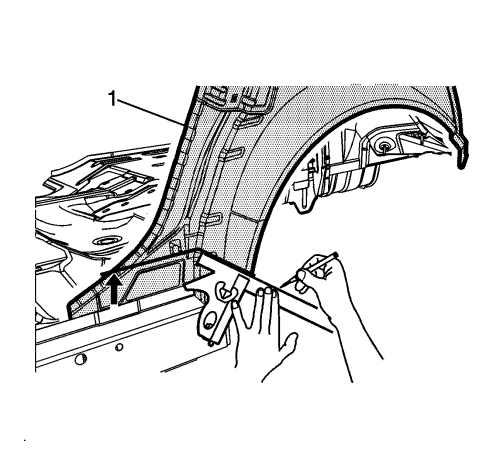
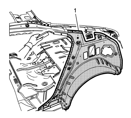
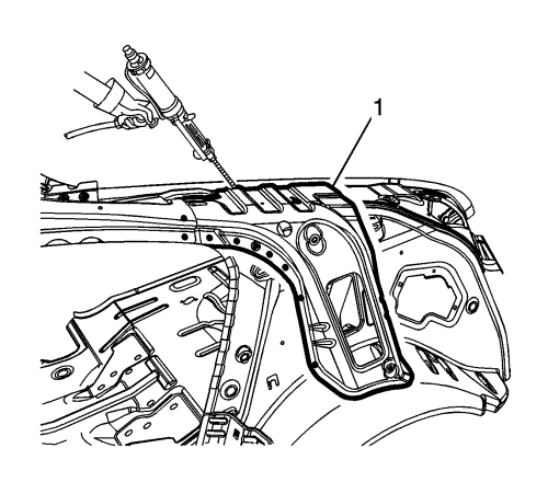
- Create a cut line on the body side inner panel (1) 60 mm (2.35 in) above the rocker outer panel flange.
- Cut the body side inner panel (1) where sectioning is to be performed.
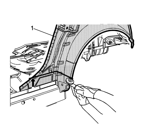
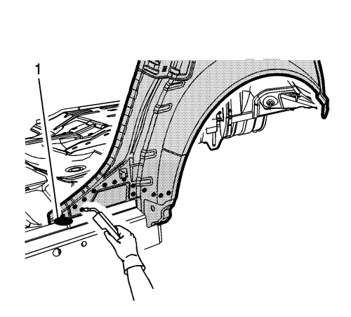
- Locate and drill out all factory welds on the body side inner panel (1). Note the number and location of the welds for installation of the service assembly.
- Remove the damaged body side inner panel (1).
Installation Procedure
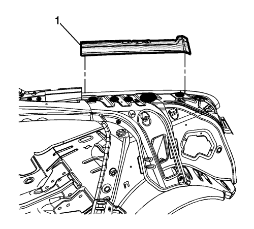
- Cut the body side inner service assembly 65 mm (2.5 in) longer at the sectioned joint (1). It should overlap the remaining portion of the original panel.
- Drill 8 mm (5/16 in) plug weld holes in the service part (1), as necessary, in the corresponding locations noted on the original panel and along sectioned joint.
- Prepare all mating surfaces as necessary.
- Apply GM-approved Weld-Thru Coating or equivalent to all mating surfaces. Refer to Anti-Corrosion Treatment and Repair .
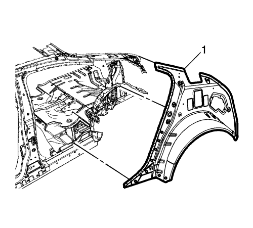
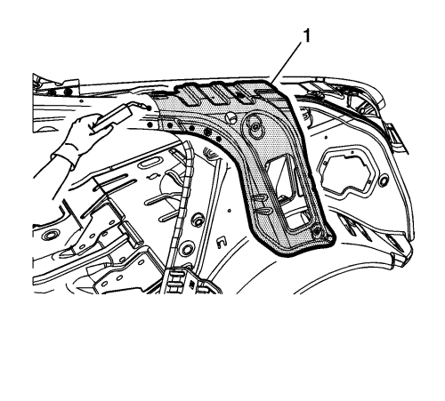
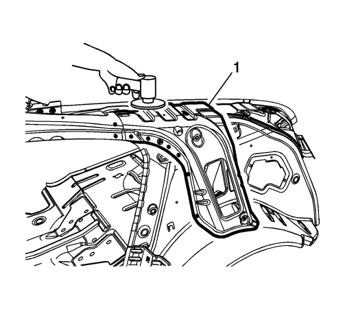
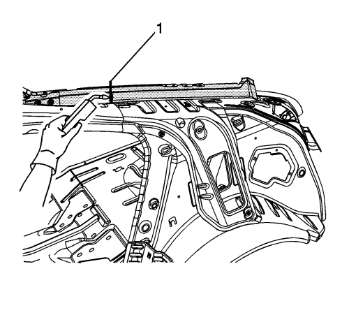
- Position the quarter inner panel (1) to the vehicle using 3-dimensional measuring equipment. Clamp the panel in place.
- Plug weld the body side inner panel (1) accordingly.
- To create a solid weld with minimum heat distortion, make 25 mm (1 in) stitch welds along the seam (1) with 25 mm (1 in) gaps between them. Then go back and complete the stitch weld.
- Prepare all mating surfaces as necessary.
- Position the body lock pillar upper reinforcement (1) to the vehicle using 3-dimensional measuring equipment. Clamp the panel in place.
- Clean and prepare the attaching surfaces for welding.
- Plug weld the body lock pillar upper reinforcement (1) accordingly.
- Grind to bare metal in areas (1) where structural adhesive was present on both attaching parts.
Note : The adhesive has a 40-50 minute working time.
- Apply a 3-6 mm (1/8-1/4 in) bead of metal panel bonding adhesive (1) or equivalent, to both of the mating surfaces (1) to attach quarter panel extension.
- Using a small brush, spread a coat of adhesive to cover all the bare metal surfaces to ensure corrosion protection.
- Position the quarter panel extension (1) to the vehicle using 3-dimensional measuring equipment. Clamp the panel in place. If adjustments are needed, slide the panels to realign. Do not pull apart.
- To create a solid weld with minimum heat distortion, make 25 mm (1 in) stitch welds along the seam (1) with 25 mm (1 in) gaps between them. Then go back and complete the stitch weld.
- Prepare all mating surfaces as necessary.
- Apply the sealers and anti-corrosion materials to the repair area, as necessary. Refer to Anti-Corrosion Treatment and Repair .
- Complete sectioning quarter panel outer. Refer to Quarter Outer Panel Sectioning .
- Prepare all mating surfaces as necessary.
- Apply the sealers and anti-corrosion materials to the repair area, as necessary. Refer to Anti-Corrosion Treatment and Repair .
- Paint the repaired area. Refer to Basecoat/Clearcoat Paint Systems .
- Install all related panels and components.
- If disabled, enable the high voltage system. Refer to High Voltage Enabling .
- Enable the SIR system. Refer to SIR Disabling and Enabling .
| ©© Copyright Chevrolet. All rights reserved |


