Front Bumper Impact Bar Replacement
Danger: Always perform the High Voltage Disabling procedure prior to servicing any High Voltage component or connection. Personal Protection Equipment (PPE) and proper procedures must be followed.
The High Voltage Disabling procedure will perform the following tasks:
| • | Identify how to disable high voltage. |
| • | Identify how to test for the presence of high voltage. |
| • | Identify condition under which high voltage is always present and personal protection equipment (PPE) and proper procedures must be followed. |
| • | Safety glasses with appropriate side shields when within 15 meters (50 feet) of the vehicle, either indoors or outdoors. |
| • | Certified and up-to-date Class "0" Insulation gloves rated at 1000V with leather protectors. |
| - | Visually and functionally inspect the gloves before use. |
| - | Wear the Insulation gloves with leather protectors at all times when working with the high voltage battery assembly, whether the system is energised or not. |
Removal Procedure
Warning : Refer to Approved Equipment for Collision Repair Warning in the Preface section.
Warning : Refer to Glass and Sheet Metal Handling Warning in the Preface section.
- Disable the SIR system. Refer to SIR Disabling and Enabling .
- Inspect the high voltage system. Refer to High Voltage System Inspection .
- Remove all related panels and components.
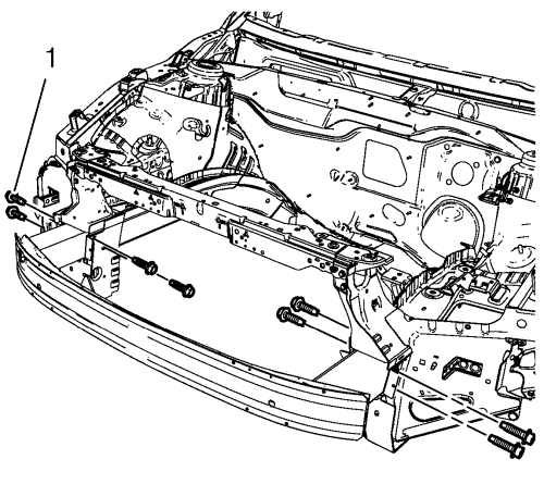
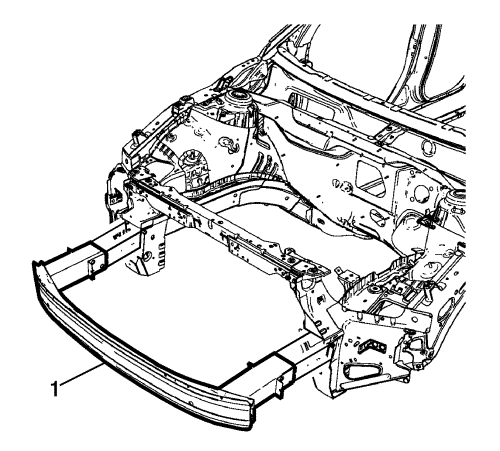
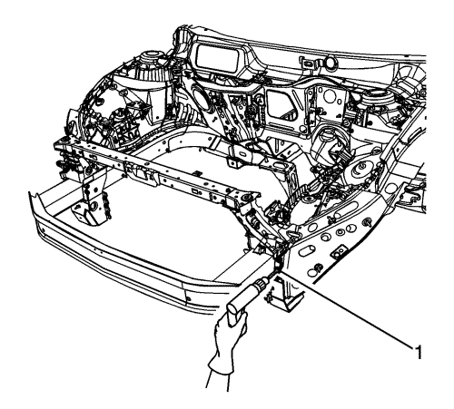
- Remove the 8 front bumper impact bar bolts (1).
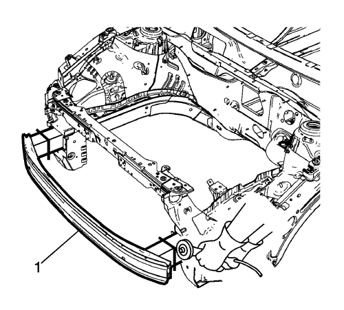
- Cut the front bumper impact bar (1) left and right.
- Locate and mark all factory welds.
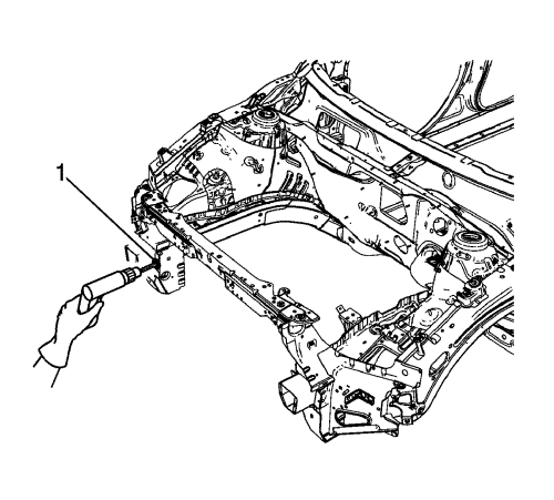
- Drill all factory welds (1).
- Remove the remaining parts of the front bumper impact bar (1).
Installation Procedure
Structural Rivet Method
Note : The original bumper impact bar bracket to lower rail welds are required to maintain structural integrity of the bumper system. However, as an alternative to MIG plug-welding, structural rivets may be used as a one-to-one weld substitution.
- Position the service front bumper impact bar (1) to the vehicle.
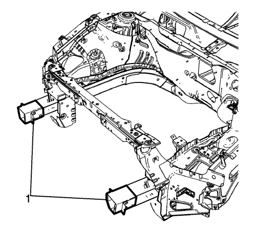
- Drill 7 mm (17/64 in) holes (1) for the structural rivets as noted from the original spot weld locations.
- Apply GM Super Lube or equivalent to drilled locations for corrosion protection.
- Install structural rivets (1) - GM part number 11610245 or equivalent.
Caution : Refer to Fastener Caution in the Preface section.
Note : Use only the original front bumper impact bar bolts. Replace bolts if damaged.
- Install the 8 front bumper impact bar bolts (1) and tighten to 110 N·m (81 lb ft).
- Install all related panels and components.
- Enable the high voltage system. Refer to High Voltage Enabling .
- Enable the SIR system. Refer to SIR Disabling and Enabling .
MIG Welding Method
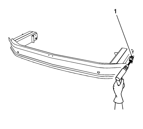
- Drill 8 mm (5/16 in) plug weld holes (1) in the service part as necessary in the locations noted from the original panel.
- Prepare all attachment surfaces as necessary.
- Apply GM-approved weld-thru coating or equivalent to all mating surfaces. Refer to Anti-Corrosion Treatment and Repair .
- Position the bumper impact bar (1) to the vehicle.
Caution : Refer to Fastener Caution in the Preface section.
Note : Use only the original front bumper impact bar bolts. Replace bolts if damaged.
- Install the 8 front bumper impact bar bolts (1) and tighten to 110 N·m (81 lb ft).

- Plug weld (1) accordingly.
- Clean and prepare all welded surfaces.
- Apply the sealers and anti-corrosion materials to the repair area, as necessary. Refer to Anti-Corrosion Treatment and Repair .
- Paint the repaired area. Refer to Basecoat/Clearcoat Paint Systems .
- Install all related panels and components.
- If disabled, enable the high voltage system. Refer to High Voltage Enabling .
- Enable the SIR system. Refer to SIR Disabling and Enabling .
| ©© Copyright Chevrolet. All rights reserved |


