Volt |
||||||||
|
|
|
|||||||
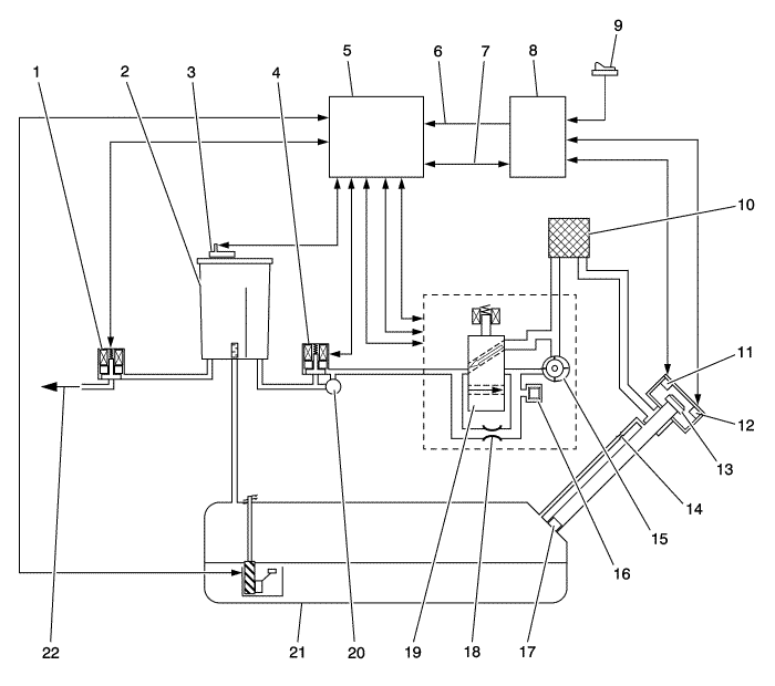
| (1) | Evaporative Emissions (EVAP) Purge Solenoid Valve |
| (2) | EVAP Canister |
| (3) | Fuel Tank Pressure Sensor |
| (4) | EVAP Vent Solenoid Valve |
| (5) | Engine Control Module (ECM) |
| (6) | Accessory Wake-up Line |
| (7) | Serial Data Communication |
| (8) | Hybrid Powertrain Control Module 2 with Alarm Clock |
| (9) | Refuel Request Switch |
| (10) | Fresh Air Filter |
| (11) | Fuel Fill Door Lock Solenoid |
| (12) | Fuel Fill Door Position Sensor |
| (13) | Fuel Filler Cap |
| (14) | 2.54 mm (0.100 in) Orifice in Fuel Fill Vapor Recirculation Pipe |
| (15) | EVAP Leak Detection Pump |
| (16) | EVAP Leak Detection Pump Sensor |
| (17) | Fuel Fill Pipe Inlet Check Valve |
| (18) | EVAP Leak Detection Pump Reference Orifice 0.51 mm (0.020 in) |
| (19) | EVAP Leak Detection Pump Switching Valve |
| (20) | Relief Valve |
| (21) | Fuel Tank |
| (22) | To Engine Inlet Manifold Vacuum |
The evaporative emission (EVAP) control system limits fuel vapours from escaping into the atmosphere. Fuel tank vapours are allowed to move from the fuel tank, due to pressure in the tank, through the EVAP vapour tube, into the EVAP canister. Carbon in the canister adsorbs and stores the fuel vapors. The EVAP canister stores the fuel vapors until the engine is able to use them.
This vehicles sealed fuel system features a normally sealed fuel tank and canister to reduce canister loading during daily cycles. Different than the EVAP diagnostic hardware from conventional EVAP systems this vent solenoid valve is normally closed. This keeps the fuel vapor sealed in the fuel tank and canister. The vent solenoid valve is only open for canister purge, refueling, fuel tank pressure (FTP) sensor correlation or leak check with the EVAP leak detection pump. Additional, excessive pressure is vented through the vent hose and EVAP canister vent solenoid valve to the atmosphere at a predetermined limit. Diagnostics are performed with the propulsion system ON and OFF.
The engine control module (ECM) wake-up timer, which is located in the Hybrid Powertrain Control Module 2, activates the ECM at three predetermined times so that leak detection can occur. This is where the EVAP leak detection pump hardware is used. The ECM uses several tests to determine if the EVAP system is leaking or restricted. These tests execute with the engine OFF at 5, 7, or 9.5 hours after the vehicle has been shut OFF. These soak times allow the fuel temperature and pressure to stabilised.
EVAP purge flow, FTP sensor and EVAP leak detection pump sensor performance diagnostics are conducted.
This vehicle does not have a purge solenoid leak test. A leaking purge solenoid will set DTCs P0442 or P0455.
This vehicle does not have a engine running version of the large leak diagnostic. The large leak diagnostic only runs when the propulsion system is not active. This is accomplished by using the EVAP leak detection pump hardware and a prior refuelling event was detected.
This vehicle does not use the engine OFF natural vacuum diagnostic for small leak detection. Instead it uses the EVAP leak detection pump hardware. This test executes when the propulsion is not active at 5, 7, or 9.5 hours after the vehicle has been shut OFF.
The EVAP system consists of the following components:
The EVAP purge solenoid valve controls the flow of vapours from the EVAP system to the inlet manifold. The purge solenoid valve opens when commanded ON by the ECM. This normally closed valve is pulse width modulated (PWM) by the ECM to precisely control the flow of fuel vapor to the engine. This valve will also be opened during some portions of the EVAP testing when the engine is running, allowing engine vacuum to enter the EVAP system.
The canister is filled with carbon pellets used to adsorb and store fuel vapors. Fuel vapor is stored in the canister until the ECM determines that the vapor can be consumed in the normal combustion process.
The FTP sensor measures the difference between the pressure or vacuum in the fuel tank and outside air pressure. The ECM provides 5 V reference, ground and signal circuit to the FTP sensor. Depending on the vehicle, the sensor can be located in the vapour space on top of the fuel tank, in the vapour tube between the canister and the tank, or on the EVAP canister. The FTP sensor provides a signal voltage back to the ECM that can vary between 0.15-4.85 V. A high FTP sensor voltage indicates a fuel tank pressure. A low FTP sensor voltage indicates a fuel tank vacuum.
The EVAP vent solenoid valve controls fresh airflow into the EVAP canister. The EVAP vent solenoid valve is normally closed. This keeps vent fuel vapor sealed in the fuel tank and canister. The EVAP vent solenoid valve is similar to a conventional vent valve, but a conventional vent valve is normally open. This vent solenoid valve is only open for canister purge, refuelling, fuel tank pressure sensor correlation or leak check with the EVAP leak detection pump.
This is a mechanical pressure relieve valve that is part of the vent solenoid valve assembly. It protects the fuel tank by relieving excessive pressure or excessive vacuum that could build up in the sealed fuel tank from environmental changes.
The leak detection pump assembly consists of three main components. These components are integral parts of the EVAP leak detection pump assembly and are not serviceable.
| • | EVAP leak detection pump with reference orifice |
| • | EVAP leak detection pump switching valve |
| • | EVAP leak detection pump pressure sensor |
This leak detection pump assembly is used for FTP sensor correlation and leak checking the EVAP system for small and large system leaks.
| • | EVAP leak detection pump pressure sensor's primary purpose is to perform leak detection diagnostics. The sensor itself is diagnosed by a correlation to barometric pressure based off the MAP sensor. |
| • | EVAP leak detection pump 0.51mm (0.020 in) reference orifice, working in conjunction with the EVAP leak detection pump and pressure sensor. This orifice is used to establish a vacuum reference baseline for diagnosing EVAP leaks |
| • | EVAP leak detection pump switching valve switches from a vent position to a pump position depending on the EVAP diagnostics taking place. |
An in-line 5 micron air filter exists between the EVAP leak detection pump fresh air inlet and behind the fuel tank fill door pocket to keep the pump hardware from becoming contaminated.
A vapor path between the fuel fill pipe and the fuel tank is necessary to fully diagnose the EVAP system. It also accommodates service diagnostic procedures by allowing the entire EVAP system to be diagnosed from the either end of the system.
The orifice aids refuelling, onboard refueling vapor recovery (ORVR), to avoid canister overload while still allowing closed system leak detection and compliance with ORVR emissions standards.
Prevents fuel fill door opening prior to pressing the Refuel Request Switch.
Provides input to the Hybrid Powertrain Control Module 2 to determine if the door position is open or closed.
The fuel fill cap is equipped with a seal and has no relief valve.
The check valve on the fuel fill pipe prevents spit-back during refuelling.
Note: There is a 30 minute time frame for refuelling to occur. If testing the EVAP system the vent solenoid valve will go back to it's normal closed state after 30 min.
Note: If more time is needed a second 1 second press of the switch will be required. Or use the scan tool to command the vent solenoid open, if necessary, for additional testing.
Located in the driver's door panel, this switch when pressed for 1 second, puts the EVAP diagnostics into an abort state, opens the vent solenoid valve for refuelling and releases the fuel fill door. A message will be displayed on the driver information centre. There is a 30 second timer on the door release mechanism allowing sufficient time to press on the fuel door to open it. If 30 seconds lapses before the fuel door is opened a second press of the refuel request switch will be required.
| ©© Copyright Chevrolet. All rights reserved |


