Drive Motor Generator Power Inverter Module Cable Inspection
Danger: Always perform the High Voltage Disabling procedure prior to servicing any High Voltage component or connection. Personal Protection Equipment (PPE) and proper procedures must be followed.
The High Voltage Disabling procedure will perform the following tasks:
| • | Identify how to disable high voltage. |
| • | Identify how to test for the presence of high voltage. |
| • | Identify condition under which high voltage is always present and personal protection equipment (PPE) and proper procedures must be followed. |
Note: This procedure is for inspection and repair of the 3 phase high voltage cable outer sheathing only.
Visual/Physical Inspection
Cable Construction
| • | Outer Jacket or Sheathing |
| • | 3 Individual Cables per Cable Assembly (Motor A or Motor B) |
- Disconnect or remove the drive motor with generator control module cover to gain better visibility of 3 phase cables.
- Determine if the exposure is limited to the braided shield or has penetrated to the insulated conductor.
- If the conductor wire is exposed, the cable assembly should be replaced.
Note: If the 3 phase cable drive motor with generator control module connector is removed a new seal must be used.
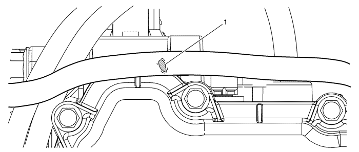
- Examine the cables for abrasion or damage. It may be necessary to disconnect the 3 phase cable from the drive motor with generator control module (TPIM) (1 bolt per connector) for proper examination.
- If exposure is limited to the braided shield, the cable can be repaired using the instructions in this procedure.
- If the damage (1) is within 100 mm of the end gate clamp on the cable then the cable should be replaced.
- If the damage (1) is more than 25 mm in length then the cable should be replaced.
- An example of a cable that can be repaired is shown above.
Cable Repair Process
Note: This procedure requires the use of Self-fusing Silicone Repair Tape.
- If abrasion or damage is evident on the outer sheathing and a repair can be made please follow the procedure below closely.
- Clean the cable area on either side of the abrasion or damage approximately 6 inches.
- Before beginning to tape the cable, you must cut the Silicone Repair Tape to the length you expect to use.
- You must also remove the Silicone Repair Tape from the backing material.
Note: Tape is pulled to half of it's original width during entire application (Very Important).
- Wrap tape around cable twice while stretching tape.
- Wrap tape along cable.
| 6.1. | Begin to spiral the tape along cable - Be sure to stretch tape while spiralling along cable. |
| 6.2. | Tape must be overlapped on itself so that there are always 2 tape layers on cable. |
- Finish applying tape by ending spiral and then wrap the tape twice on itself (like step 5) and tear or cut remaining tape and smooth onto itself.
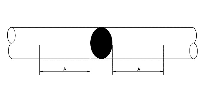
- The Silicone Rescue Tape must wrap the cable to provide 1.25 in (A) of coverage from edge of damage on each side of the abrasion or damaged area.
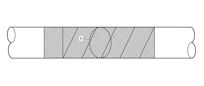
- You can see above the abrasion or damage "spot (1)" covered by Silicone Rescue Tape.
- If connector/s to TPIM were removed install with new seal and torque to 9.5 N·m +/-- 1.5 N·m (84 lb in +/-- 1 1/2 lb in).
- Install drive motor with generator control module cover.
| ©© Copyright Chevrolet. All rights reserved |


