Valve Stem Oil Seal and Valve Spring Replacement
Special Tools
| • | EN-6086 Basic Kit, Spring and Wedge Replacer |
| • | EN-840 Pliers / Remover |
For equivalent regional tools, refer to Special Tools .
Removal Procedure
- Raise and support the vehicle. Refer to Lifting and Jacking the Vehicle .
- Remove the right front wheel house liner. Refer to Front Wheelhouse Rear Liner Replacement .
- Lower the vehicle.
- Remove the hydraulic valve clearance adjuster arms. Refer to Hydraulic Valve Clearance Adjuster Arm Replacement .
- Remove the spark plugs. Refer to Spark Plug Replacement .
- Adjust the engine to TDC of cylinder 1 and fix the crankshaft. Refer to Camshaft Timing Chain Adjustment .
Inlet Valve Stem Oil Seal Removal Cylinder 1
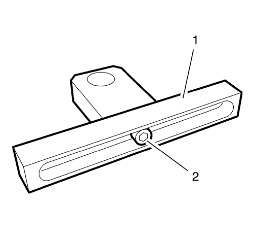
- Prepare the 2 EN-6086-6 supports (1) for the installation by tightening the support head in a centred position to the rail with the bolt (2).
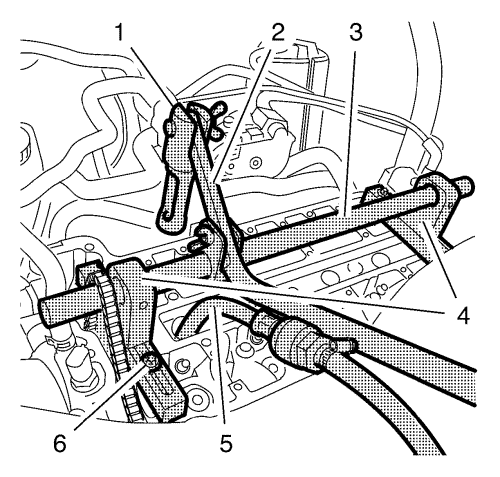
- Install the EN-6086-5 mounting shaft (3) along with the 2 EN-6086-6 supports (4) and the EN-6086-8 handle to the cylinder head.
Note: The demounting piece must point to the inlet side.
- Install the EN-6086-7 lever (2) along with the EN-6086-11 demounting piece (1) to the mounting shaft.
- Position the mounting shaft centred above the spark plug bores and tighten the 4 fasteners (6).
- Install the EN-6086-15 pneumatic adapter (5) to the spark plug screw bore of cylinder 1.
- Apply air pressure to cylinder 1.
- Remove the valve keys, valve spring retainers and the valve springs of the intake valves of cylinder 1, using the following procedure:
Caution: The demounting piece part of EN-6086 Basic Kit, Spring and Wedge Replacer must be applied parallel to the valve retainers in order to prevent damage to the tools or the valve train components. If demounting piece is not applied parallel it could cause damage to the valve stem keys or the valve retainers.
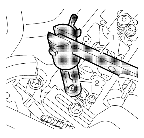
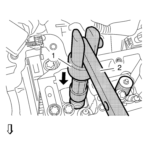
| 7.1. | Apply tension to the valve springs, using the EN-6086-7 lever (1) and the EN-6086-11 demounting piece (2) until the valve keys are discharged from spring load and remove the valve keys. |
| 7.2. | Release tension from the valve springs and remove the valve spring retainers and the valve springs. |
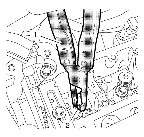
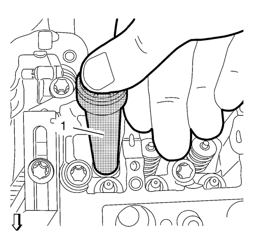
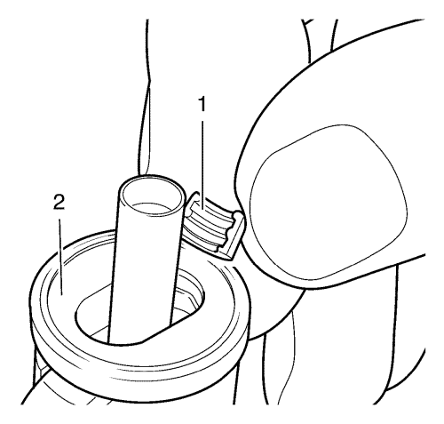
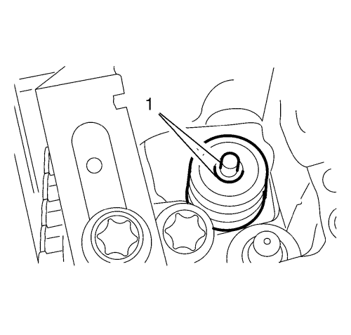
- Remove the inlet valve stem oil seals (2) of cylinder 1, using the EN-840 pliers (1).
Inlet Valve Stem Oil Seal Installation Cylinder 1
Note: Lubricate the NEW inlet valve stem oil seals with clean engine oil.
- Install the NEW inlet valve stem oil seals of cylinder 1, using the EN-958 installer (1).
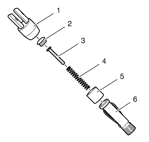
- Prepare the EN-6086-200-1 mounting piece for the valve key installation. The mounting piece must be assembled in the following order:
| 2.4. | EN-6086-200-10 plunger (3) |
| 2.5. | Screw Connection (2) |
- Install the valve keys (1) to the mounting piece (2) and fix them with the bushing.
- Install the inlet valve springs, the inlet valve spring retainers and the inlet valve keys, using the following procedure:
| 4.1. | Replace the EN-6086-11 demounting piece with the assembled EN-6086-200-1 mounting piece (1). |
| 4.2. | Install the inlet valve springs and the inlet valve spring retainers to the cylinder head. |
Caution: The demounting piece part of EN-6086 Basic Kit, Spring and Wedge Replacer must be applied parallel to the valve retainers in order to prevent damage to the tools or the valve train components. If demounting piece is not applied parallel it could cause damage to the valve stem keys or the valve retainers.
| | Note: The cone side of the valve keys must point to the valve stem. |
| 4.3. | Push down the mounting piece (1) using the lever (2) until the valve keys are audible engaged. |
| 4.4. | Inspect the inlet valve keys (1) for proper seating. |
Exhaust Valve Stem Oil Seal Removal Cylinder 1
Remove the exhaust valve stem oil seals of cylinder 1:
- Transfer the EN-6086-7 lever to the exhaust side of cylinder 1.
- Replace the EN-6086-200-1 mounting piece with the EN-6086-11 demounting piece .
- Remove the exhaust valve keys, exhaust valve spring retainers, exhaust valve springs and the exhaust valve stem oil seals as described above.
Exhaust Valve Stem Oil Seal Installation Cylinder 1
- Replace the EN-6086-11 demounting piece with the assembled EN-6086-200-1 mounting piece (1).
- Install the exhaust valve keys, exhaust valve spring retainers, exhaust valve springs and the exhaust valve stem oil seals of cylinder 1 as described above.
Inlet Valve Stem Oil Seal Removal Cylinder 4
- Release the air pressure from cylinder 1.
- Transfer the EN-6086-15 pneumatic adapter from cylinder 1 to the spark plug bore of cylinder 4.
- Apply air pressure to cylinder 4.
- Transfer the EN-6086-7 lever to the inlet side of cylinder 4.
- Replace the EN-6086-200-1 mounting piece with the EN-6086-11 demounting piece .
- Remove the inlet valve keys, inlet valve spring retainers, inlet valve springs and the inlet valve stem oil seals of cylinder 4 as described above.
Inlet Valve Stem Oil Seal Installation Cylinder 4
- Replace the EN-6086-11 demounting piece with the assembled EN-6086-200-1 mounting piece .
- Install the inlet valve keys, inlet valve spring retainers, inlet valve springs and the inlet valve stem oil seals of cylinder 4 as described above.
Exhaust Valve Stem Oil Seal Removal And Installation Cylinder 4
Replace the exhaust valve keys, exhaust valve spring retainers, exhaust valve springs and the exhaust valve stem oil seals of cylinder 4 as described above.
Inlet Valve Stem Oil Seal Removal Cylinder 2
- Release the air pressure from cylinder 4.
- Transfer the EN-6086-15 pneumatic adapter from cylinder 4 to the spark plug bore of cylinder 2.
- Apply air pressure to cylinder 2.
- Transfer the EN-6086-7 lever to the inlet side of cylinder 2.
- Replace the EN-6086-200-1 mounting piece with the EN-6086-11 demounting piece .
- Remove the inlet valve keys, inlet valve spring retainers, inlet valve springs and the inlet valve stem oil seals of cylinder 2 as described above.
Inlet Valve Stem Oil Seal Installation Cylinder 2
- Transfer the EN-6086-7 lever to the exhaust side of cylinder 2.
- Replace the EN-6086-11 demounting piece with the assembled EN-6086-200-1 mounting piece (1).
- Install the inlet valve keys, inlet valve spring retainers, inlet valve springs and the inlet valve stem oil seals of cylinder 2 as described above.
Exhaust Valve Stem Oil Seal Removal And Installation Cylinder 2
Replace the exhaust valve keys, exhaust valve spring retainers, exhaust valve springs and the exhaust valve stem oil seals of cylinder 2 as described above.
Inlet Valve Stem Oil Seal Removal Cylinder 3
- Release the air pressure from cylinder 2.
- Transfer the EN-6086-15 pneumatic adapter from cylinder 2 to the spark plug bore of cylinder 3.
- Apply air pressure to cylinder 3.
- Transfer the EN-6086-7 lever to the intake side of cylinder 3.
- Replace the EN-6086-200-1 mounting piece with the EN-6086-11 demounting piece .
- Remove the inlet valve keys, inlet valve spring retainers, inlet valve springs and the inlet valve stem oil seals of cylinder 3 as described above.
Inlet Valve Stem Oil Seal Installation Cylinder 3
- Transfer the EN-6086-7 lever to the exhaust side of cylinder 3.
- Replace the EN-6086-11 demounting piece with the assembled EN-6086-200-1 mounting piece .
- Install the inlet valve keys, inlet valve spring retainers, inlet valve springs and the inlet valve stem oil seals of cylinder 3 as described above.
Exhaust Valve Stem Oil Seal Removal And Installation Cylinder 3
Replace the exhaust valve keys, exhaust valve spring retainers, exhaust valve springs and the exhaust valve stem oil seals of cylinder 3 as described above.
Installation Procedure
- Release air pressure from cylinder 3.
- Remove the EN-6086-15 pneumatic adapter.
- Remove all parts of EN-6086 spring and wedge replacer .
- Shift to neutral gear and release the park brake.
- Install the spark plugs. Refer to Spark Plug Replacement .
- Install the hydraulic valve clearance adjuster arms. Refer to Hydraulic Valve Clearance Adjuster Arm Replacement .
- Raise the vehicle.
- Remove the EN-952 fixing pin and install the crankshaft bearing cap tie plate hole plug. Refer to.
- Install the right front wheelhousing lining. Refer to Front Wheelhouse Rear Liner Replacement .
- Lower the vehicle.
| ©© Copyright Chevrolet. All rights reserved |


