Volt |
||||||||
|
|
|
|||||||
This vehicle is equipped with three fully independent cooling systems. The hybrid/EV electronics cooling system is dedicated to cooling the battery charger and the drive motor generator power inverter module. The hybrid/EV battery pack cooling system is dedicated to cooling and heating the high-voltage hybrid/EV battery. The engine cooling system is dedicated to cooling the engine and providing heat to the passenger compartment.
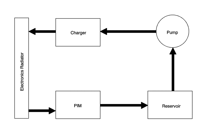
The primary purpose of the hybrid/EV electronics cooling loop is to cool the drive motor generator power inverter module, while propulsion is enabled, and the on-board charge module, when it is plugged in. The hybrid/EV electronics cooling system uses the hybrid/EV electronics radiator, the two 12 V pulse width modulated (PWM) radiator fans, a 12 V hybrid/EV electronics coolant pump to circulate coolant through the drive motor generator power inverter module and the drive motor battery charger. The hybrid/EV powertrain control module 2 activates the hybrid/EV electronics coolant pump and monitors a temperature sensor in the hybrid/EV electronics radiator. The hybrid/EV powertrain control module 2 monitors the hybrid/EV electronics cooling system temperature to determine when to operate the radiator fans. The hybrid/EV electronics coolant pump will be activated when the vehicle is on and during charging. The hybrid/EV electronics radiator is combined with the battery pack cooling system radiator to form one radiator assembly. The hybrid/EV electronics coolant pump and radiator cooling fans will also be enabled during an after-run event which is determined by coolant loop temperature.
The hybrid/EV electronics cooling system circulates a pre-mixed DEXCOOL® which is a 50/50 mixture of DEXCOOL® and deionised water. Deionised water is required for high-voltage isolation and to prevent corrosion from affecting heat sink performance. Always use pre-mixed coolant and never use tap water in the hybrid/EV electronics coolant system.
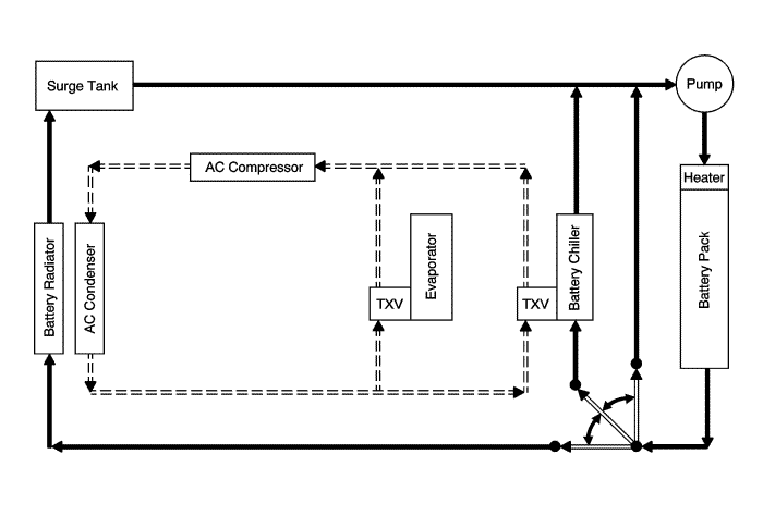
The energy storage system cooling system uses a battery radiator, the two 12 V pulse width modulated (PWM) radiator fans, a 12 V hybrid/EV battery pack coolant pump, a refrigerant/coolant heat exchanger (chiller), the electric A/C compressor motor control module assembly, refrigerant pressure and temperature sensors, ambient air temperature sensor and a hybrid/EV battery pack coolant flow control valve to cool down the high voltage hybrid/EV battery. There is also a high-voltage heater inside the hybrid/EV battery to heat the coolant entering the hybrid/EV battery when needed. The hybrid/EV powertrain control module 2 monitors the hybrid/EV battery coolant temperature, hybrid/EV battery cell temperature, refrigerant temperature and refrigerant pressure. The hybrid/EV powertrain control module 2 determines how much hybrid/EV battery cooling or heating is required and turns on the hybrid/EV battery pack coolant pump, positions the hybrid/EV battery pack coolant flow control valve and depending on what is required will operate the radiator fans, request the A/C Compressor Module to turn on the high-voltage A/C compressor or turn on the high voltage hybrid/EV battery pack heater. The hybrid/EV battery pack cooling system could be activated when the vehicle is operating, during charging, or when the vehicle is OFF and maintaining the hybrid/EV battery pack temperature. Refer to Automatic HVAC Description and Operation .
The Hybrid/EV Battery Pack Coolant Control Valve is used to manage the flow of coolant circulating through the hybrid/EV battery temperature control system. The valve has one fluid input port and three fluid output ports, identified as Radiator, Bypass and Chiller. The valve has an internal valve body that is rotated by the valve motor to different positions to control which fluid ports are connected. The valve operates through 90 degrees. When the valve is directing coolant to the Radiator port, coolant is routed through a front-mounted heat exchanger. When the valve is in the Bypass position, coolant is routed through the battery pack without passing through additional heat exchangers. When the valve is in the Chiller position coolant is routed through a heat exchanger that allows the A/C cooling system to reduce coolant temperature. The valve can be moved to several intermediate positions between Bypass and Chiller, for blended cooling of the hybrid/EV battery pack coolant for optimum efficiency.
The valve provides position feedback to the hybrid/EV powertrain control module 2 based on a potentiometer in the valve. The hybrid/EV powertrain control module 2 uses this feedback to monitor the valve position. Different valve positions correspond to different resistance values. When the ignition is first turned on the hybrid/EV powertrain control module 2 determines and records the sensor values corresponding to the end-stop positions of the valve by moving the valve to an end-stop and back to its original position. This is referred to as the hybrid/EV powertrain control module 2 "diagnostic learn" of the valve. This provides a valve shaft breakage test and allows the hybrid/EV powertrain control module 2 to "learn" the position feedback value that corresponds to that end-stop. The end-stop that is used at each ignition key cycle alternates between each end-stop.
The hybrid/EV battery pack cooling system circulates a pre-mixed DEXCOOL® which is a 50/50 mixture of DEXCOOL® and deionised water. Deionised water is required for high-voltage isolation and to prevent corrosion from affecting heat sink performance. Always use pre-mixed coolant and never use tap water in the battery coolant system.
The passenger compartment heater coolant control valve is also controlled by hybrid/EV powertrain control module 2 to assist in regulating passenger compartment comfort based on presence or absence of engine heat. Refer to Automatic HVAC Description and Operation .
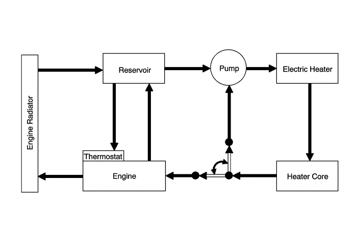
The passenger compartment heater system uses the engine radiator, the two 12 V pulse width modulated (PWM) radiator fans, a 12 V auxiliary heater coolant pump, a passenger compartment heater coolant control valve, a high- voltage coolant heater control module and a heater core. The hybrid/EV powertrain control module 2 operates the two radiator fans in response to engine temperature.
The passenger compartment heater coolant control valve has two positions. When commanded in bypass mode, as when the engine is OFF, the passenger compartment heater coolant control valve separates the engine and the cabin heater control module coolant loops to prevent heat generated by the cabin heater control module for passenger compartment heating from dissipating into the engine coolant loop. After the engine starts up and is warmed up, excess engine heat will allowed to assist the cabin heater control module in heating the passenger compartment; the passenger compartment heater coolant control valve is commanded to link mode and the two coolant loops are connected.
The HVAC control module turns on the auxiliary heater coolant pump and monitors the temperature sensors in the passenger compartment and coolant loop to determine if the high-voltage cabin heater control module is needed. Passenger compartment heat is provided by air flowing through the heater core. The heater core is heated by coolant from the engine, the high- voltage cabin heater control module or both. The hybrid/EV powertrain control module 2 will command the position of the passenger compartment heater coolant control valve to either isolate the passenger compartment heater loop from the engine coolant loop or link the two loops together to maximize efficiency depending on the passenger compartment heat requirements. When operating the vehicle in cold temperatures, the engine may run for short periods to assist in maximising heat efficiency to the passenger compartment depending on the outside temperature and the passenger compartment heat requirements.
The hybrid/EV powertrain control module 2 will command the passenger compartment heater coolant control valve into bypass mode when the module goes to sleep, at controller wake-up, and during other times except:
| • | During learn (after extended loss of 12 V power to the controller) |
| • | When the scan tool is sending a command. |
| • | If the valve is stuck in an intermediate position (between two end positions) due to failure or debris. |
The passenger compartment heater cooling system circulates a 50/50 mixture of DEXCOOL® and distilled water.
The 14 V power module is air-cooled. Refer to Accessory Power Module Description and Operation. The 14 V power module fan is powered by a brushless DC motor and has operating speeds between 0-3,900 RPM. The 14 V power module fan is serviced separately from 14 V power module assembly. The hybrid/EV powertrain control module 2 will command the 14 V power module fan while in RUN mode.
| ©© Copyright Chevrolet. All rights reserved |


