Volt |
||||||||
|
|
|
|||||||
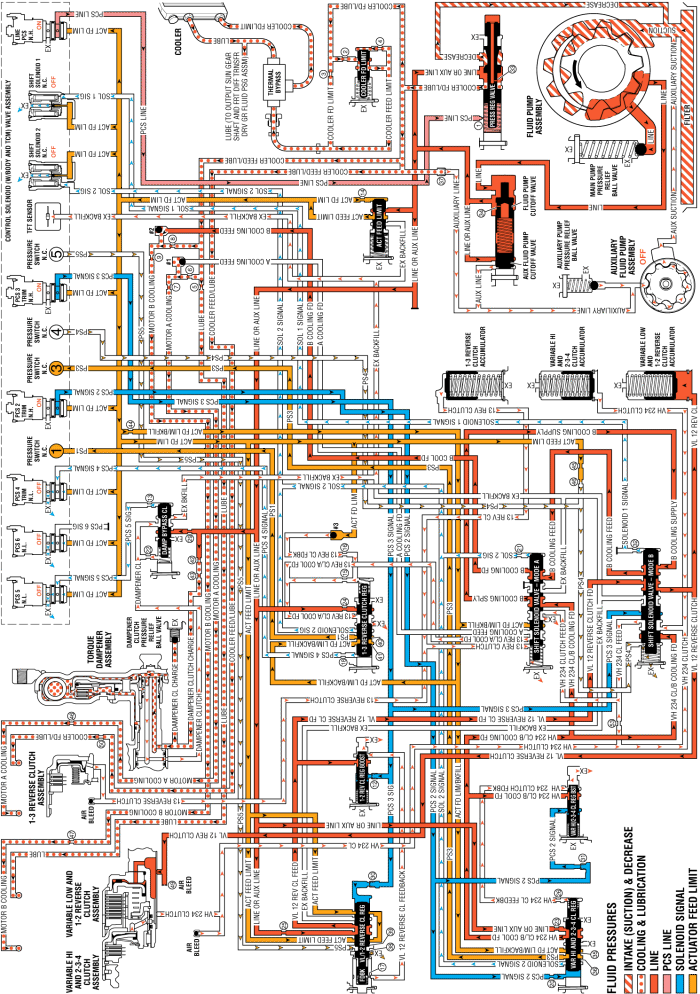
If the transmission experiences an electrical component malfunction, all solenoids will default to their normal state. The transmission will operate in Default whenever the gear selector lever is a forward range. The transmission will remain in this default state until the condition is corrected. Reverse (R) range can also still be selected. This default action enables the vehicle to be safely driven to a service centre.
When an electrical malfunction occurs, the PC solenoid 3 defaults to its normally high state (ON). Depending on the operating mode of the transmission at the time of the malfunction, the variable low and 1-2 reverse clutch is either applied or remains applied.
The PC solenoid 3 defaults to its normally high state (ON) allowing actuator feed limit fluid to enter the PCS 3 signal circuit. PCS 3 signal fluid is then routed through orifice #30 to the variable low and 1-2 reverse clutch regulator valve; through orifice #12 to the variable low and 1-2 reverse clutch boost valve; and to the shift solenoid valve -mode B.
PCS 3 signal fluid pressure acts on a differential area of the variable low and 1-2 reverse clutch boost valve, moving the valve against variable low and 1-2 reverse clutch boost valve spring force to block VL 12 reverse clutch feed fluid from entering the VL 12 reverse clutch feedback circuit, and opening the VL 12 reverse clutch feedback circuit to exhaust. This results in the variable low and 1-2 reverse clutch regulator valve moving to the full feed position, sending full VL 12 reverse clutch feed pressure (full line pressure) to the variable low and 1-2 reverse clutch.
PCS 3 signal fluid moves the variable low and 1-2 reverse clutch regulator valve, against variable low and 1-2 reverse clutch regulator valve spring force, to the applied position. This allows line or auxiliary line fluid to pass through the valve into the VL 12 reverse clutch feed circuit.
VL 12 reverse clutch feed fluid is routed to the shift solenoid valve - mode B, where it passes through the valve into the VL 12 reverse clutch circuit.
VL 12 reverse clutch fluid pressure enters the case assembly behind the variable low and 1-2 reverse clutch piston and moves the piston against spring force to apply the variable low and 1-2 reverse clutch plates.
The normally low pressure control solenoid 4 and the normally closed shift solenoid 2 default to their normal states (OFF), and the 1-3 reverse clutch is released if it was applied at the time of the malfunction.
The PC solenoid 4 is commanded OFF, allowing PCS 4 signal fluid to exhaust from the 1-3 reverse clutch regulator valve.
The shift solenoid 2 is commanded OFF, allowing solenoid 2 signal fluid to exhaust. When solenoid 2 signal fluid exhausts, the shift solenoid valve - mode A moves to the released position.
13 reverse clutch fluid pressure is exhausted from the 1-3 reverse clutch housing assembly, allowing 1-3 reverse clutch spring force to move the 1-3 reverse clutch piston and release the 1-3 reverse clutch plates.
13 reverse clutch fluid pressure exhausts at the shift solenoid valve - mode A.
13 reverse clutch feedback fluid pressure exhausts into the 13 reverse clutch/A cooling feed circuit, allowing actuator feed limit fluid to seat the ball.
1-3 reverse clutch regulator valve spring force moves the 1-3 reverse clutch regulator valve to the released position, allowing 13 reverse clutch/A cooling feed fluid pressure to exhaust.
The normally closed shift solenoid 1 and shift solenoid 2 default to their normal states (OFF), and the variable hi and 2-3-4 clutch is released if it was applied at the time of the malfunction.
The PC solenoid 2 is commanded OFF, allowing PCS 2 signal fluid to exhaust from the variable hi and 2-3-4 clutch regulator valve and the variable hi and 2-3-4 clutch boost valve.
VH 234 clutch fluid pressure is exhausted from the case assembly, allowing variable hi and 2-3-4 clutch spring force to move the variable hi and 2-3-4 clutch piston and release the variable hi and 2-3-4 clutch plates.
Exhausting VH 234 clutch fluid pressure passes through the shift solenoid valve - mode B into the VH 234 clutch feed circuit.
VH 234 clutch feed fluid pressure exhausts at the shift solenoid valve - mode A.
Variable hi and 2-3-4 clutch regulator valve spring force moves the variable hi and 2-3-4 clutch regulator valve to the released position, allowing VH 234 clutch/B cooling feed fluid pressure to exhaust.
If the torque damper clutch is applied when an electrical malfunction occurs, the clutch will release when the PC solenoid 5 defaults to its normally low state (OFF).
The PC solenoid 5 is de-energised (OFF) allowing PCS 5 signal fluid to exhaust from the damper bypass clutch valve.
Damper clutch fluid exhausts from the torque damper clutch assembly to the damper bypass clutch valve allowing the torque damper clutch to release.
Damper bypass clutch valve spring force moves the damper bypass clutch valve to the released position, allowing damper clutch fluid pressure to exhaust through the valve into the exhaust backfill circuit.
Damper clutch fluid pressure in the exhaust backfill circuit exhausts at the TFT sensor.
VL 12 reverse clutch fluid is also sent to the variable low and 1-2 reverse clutch accumulator assembly. VL 12 reverse clutch fluid moves the variable low and 1-2 reverse clutch accumulator piston against accumulator spring force to cushion the apply of the variable low and reverse clutch assembly.
13 reverse clutch fluid also exhausts from the 1-3 reverse clutch accumulator assembly. Accumulator spring force moves the 1-3 reverse clutch accumulator piston to the released position.
VH 234 clutch fluid also exhausts from the variable hi and 2-3-4 clutch accumulator assembly. Accumulator spring force moves the variable hi and 2-3-4 clutch accumulator piston to the released position.
| © Copyright Chevrolet. All rights reserved |


