300 Volt Battery Positive and Negative Cable Replacement - Drive Motor Battery-to-APM Module
Removal Procedure
Danger: Always perform the High-Voltage Disabling procedure prior to servicing any High Voltage component or connection. Personal Protection Equipment (PPE) and proper procedures must be followed.
The High-Voltage Disabling procedure will perform the following tasks:
| • | Identify how to disable high voltage. |
| • | Identify how to test for the presence of high voltage. |
| • | Identify conditions under which high voltage is always present and personal protection equipment (PPE) and proper procedures must be followed. |
| • | Safety goggles with appropriate side shields when within 15 metres (50 feet) of the vehicle, either indoors or outdoors. |
| • | Certified and up-to-date Class "0" Insulation gloves rated at 1000 V with leather protectors. |
| - | Visually and functionally inspect the gloves before use. |
| - | Wear the Insulation gloves with leather protectors at all times when working with the high-voltage battery assembly, whether the system is energised or not. |
Danger: The Volt Battery Pack will utilise an exchange program. Please consult the most recent revision of bulletin/PI #PIP4841, available in Service Information (SI), for a list of approved Volt Battery Pack service procedures. Components that may be removed and serviced without exchanging the complete battery pack are identified in the bulletin/PI. Please contact the GM Technical Assistance Centre (1-877-446-8227) if you have any questions.
- Disable the high-voltage system. Refer to High Voltage Disabling .
- Remove the drive motor battery. Refer to Drive Motor Battery Replacement and Shipping Preparation .
- Support the fuel tank with an appropriate jack.
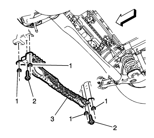
- Remove the nuts (1) and the bolts (2) securing the floor panel bar (3) to the frame.
- Remove the floor panel bar (3).
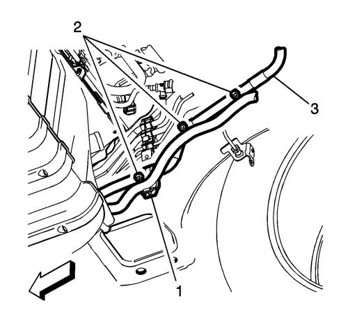
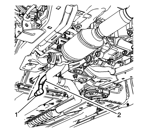
- Remove the 300 V battery positive/negative cable retainer nut (1).
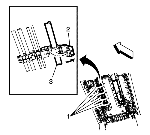
- Detach the 300 V battery positive/negative cable (3) from the fuel rail fasteners (1).
- Swing the individual fuel line clips (2) open.
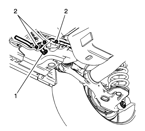
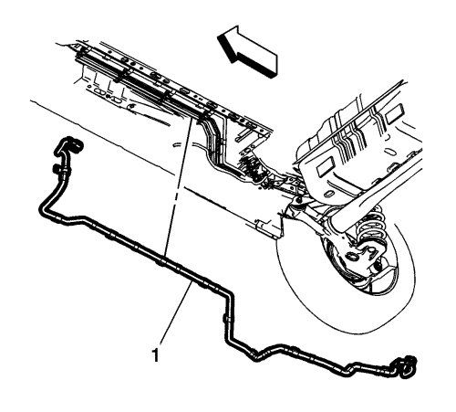
- Working towards the rear of the vehicle, detach the fuel line clip (1) and cables ties (2).
- Unclip the fuel line clip (1) and the cable ties (2).
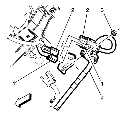
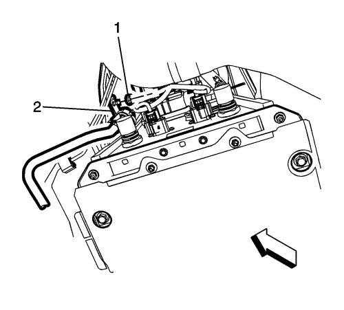
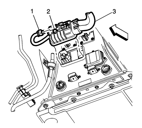
- Disconnect the high-voltage inter-lock loop connector (1) and the 300 V battery positive/negative cable connector (2).
- Remove the 300 V battery positive/negative cable fastener nut (3).
- Remove the 300 V battery positive/negative cable (1) from the vehicle.
Installation Procedure
- Position the 300 V battery positive/negative cable (1) below the vehicle.
Caution: Refer to Fastener Caution in the Preface section.
- Connect the 300 V battery positive/negative retainer and nut (3) to the bracket stud. Tighten to 8 N·m (71 lb in).
- Connect the 300 V battery positive/negative cable connector (2) to the accessory DC power control module.
- Connect the high-voltage inter-lock loop connector (1) to the accessory DC power control module.
- Install the 300 V battery positive/negative cable into the fuel line retainer with clip (1).
- Install the 300 V battery positive/negative cable into the fuel line retainer with clip (1).
- Install the floor panel bar (3) to the frame mounts. Tighten the following:
| • | Floor panel bar nuts (1) to 22 N·m (16 lb ft). |
| • | Floor panel bar bolts (2) to 58 N·m (43 lb ft). |
- Connect the 300 V battery positive/negative cable into the fuel line retainer clips (1).
- Install the drive motor battery. Refer to Drive Motor Battery Replacement and Shipping Preparation .
- Install the 300 V battery positive/negative cable retainer to the stud and tighten nut (1) to 8 N·m (71 lb in).
- Connect the 300 V battery positive/negative cable connector (3) to the drive motor battery (3).
- Connect the high-voltage inter-lock loop connector (1).
- Connect the high-voltage inter-lock loop connector (1).
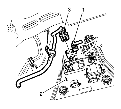
- Install the connector (3) and tighten the bolt (1) to 8 N·m (71 lb in).
- Connect the drive motor battery coolant cooler inlet hose fitting (1).
- Fill the drive motor battery cooling system. Refer to Drive Motor Battery Cooling System Draining and Filling .
- Enable the high-voltage system. Refer to High-Voltage Enabling .
- Clear the secure high-voltage DTCs. Refer to Clear Secured High-Voltage DTCs .
- Rest the Hybrid/EV battery pack data. Refer to Hybrid/EV Battery Pack Data Reset .
- Perform a Hybrid/EV battery pack capacity learn procedure. Refer to Hybrid/EV Battery Pack Capacity Learn .
| © Copyright Chevrolet. All rights reserved |


