Inflatable Restraint Module Handling and Scrapping
Live and Undeployed Air Bag
Warning: Refer to SIR Inflator Module Handling and Storage Warning in the Preface section.
Take special care when handling or storing an undeployed air bag. An air bag deployment produces a rapid generation of gas. This may cause the air bag, or an object in front of the air bag, to project through the air in the event of an unlikely deployment.
Dual Stage Air Bags
Dual stage air bags have two deployment stages. If stage 1 was used to deploy a dual stage air bag, stage 2 may still be active. Therefore, a deployed dual stage air bag must be treated as an active air bag. If disposal of a dual stage air bag is required, both deployment loops must be energised to deploy the air bag.
Scrapping Procedure
At the end of a vehicle's useful life, certain situations may arise which will require the disposal of a live and undeployed air bag. Do NOT dispose a live and undeployed air bag through normal disposal channels until the air bag has been deployed.
Do not deploy the air bag in the following situations:
| • | After replacement of an air bag under warranty--the air bag may need to be returned undeployed to the manufacturer. |
| • | If the vehicle is the subject of a product liability claim, related to the SIR system and is subject to a preliminary investigation -- do NOT alter the SIR system in any manner. |
| • | If the vehicle is involved in a campaign affecting the air bags -- follow the instructions in the campaign service bulletin for proper SIR handling procedures. |
Deployment Procedures
Note: Some countries, states or localities may not allow service deployment of air bags without special permission or training. Local laws regarding deploying and scrapping of air bags/devices with pyrotechnics must be followed.
You can only deploy the air bag inside of the vehicle.
Deployment Inside Vehicle - Vehicle Scrapping Procedure
Deploy the air bags inside of the vehicle when destroying the vehicle or when salvaging the vehicle for parts. This includes, but is not limited to, the following situations:
| • | The vehicle has completed all useful life. |
| • | Irreparable damage occurred to the vehicle in a non-deployment type accident. |
| • | Irreparable damage occurred to the vehicle during a theft. |
| • | The vehicle is being salvaged for parts to be used on a vehicle with a different VIN, as opposed to rebuilding as the same VIN. |
Warning: Refer to SIR Inflatable Module Deployment Outside Vehicle Warning in the Preface section.
- Lower the driver and passenger windows.
- Turn the ignition switch to the OFF position and remove the ignition key.
- Check that all air bags which will be deployed are mounted securely.
- Remove all loose objects from the front seats.
Warning: A deployed dual stage inflator module will look the same whether one or both stages were used. Always assume a deployed dual stage inflator module has an active stage 2. Improper handling or servicing can activate the inflator module and cause personal injury.
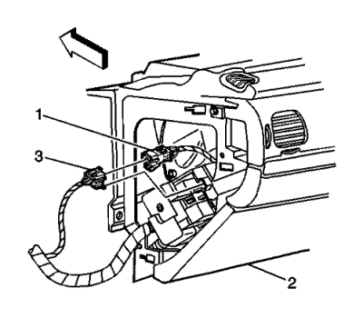
- Disconnect the steering wheel air bag yellow connector (1) from vehicle harness yellow connector (3).
Note: If the vehicle is equipped with dual stage air bags the steering wheel air bag and instrument panel air bag will each have 4 wires. Refer to Component Connector End Views for determining high and low circuits.
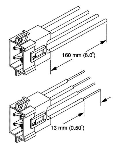
- Cut the yellow harness connector out of the vehicle, leaving at least 16 cm (6 in) of wire at the connector.
- Strip 13 mm (0.5 in) of insulation from each of the connector wire leads.
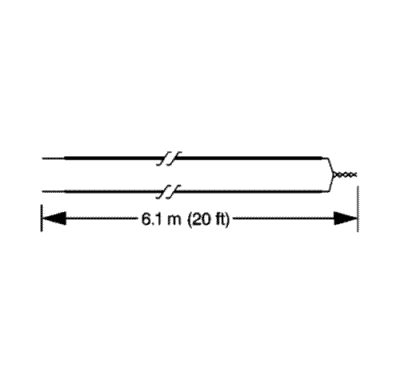
- Cut two 6.1 m (20 ft) deployment wires from a 0.8 mm (18 gauge) or thicker multi-strand wire. Use these wires to fabricate the driver deployment harness.
- Strip 13 mm (0.5 in) of insulation from both ends of the wires.
- Twist together one end from each of the wires in order to short the wires. Deployment wires shall remain shorted, and not connected to a power source until you are ready to deploy the air bag.
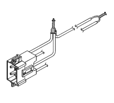
- Twist together the 2 connector wire leads from the high circuits from both stages of the steering wheel air bag, to one set of deployment wires. Refer to Component Connector End Views in order to determine the correct circuits.
- Inspect that the 3-wire connection is secure.
- Secure and insulate the 3-wire connection to the deployment harness using electrical tape.
- Twist together the 2 connector wire leads from the low circuits from both stages of the steering wheel air bag, to one set of deployment wires. Refer to Component Connector End Views in order to determine the correct circuits.
- Inspect that the 3-wire connection is secure.
- Secure and insulate the 3-wire connection to the deployment harness using electrical tape.
- Connect the deployment harness to the connector on the steering wheel air bag.
- Route the deployment harness out of the driver side of the vehicle.
- Disconnect the yellow left roof rail harness connector from the vehicle harness connector.
- Cut the harness connector out of the vehicle, leaving at least 16 cm (6 in) of wire at the connector.
- Strip 13 mm (0.5 in) of insulation from each of the connector wire leads.
- Cut two 6.1 m (20 ft) deployment wires from a 0.8 mm (18 gauge) or thicker multi-strand wire. These wires will be used to fabricate the roof rail air bag deployment harness.
- Strip 13 mm (0.5 in) of insulation from both ends of the wires.
- Twist together one end from each of the wires in order to short the wires.
- Twist together one connector wire lead to one deployment wire.
- Secure and insulate the connection using electrical tape.
- Twist together and tape the remaining connector wire lead to the remaining deployment wire.
- Connect the deployment harness to the yellow connector of the roof rail air bag.
- Route the deployment harness out of the driver side of the vehicle.
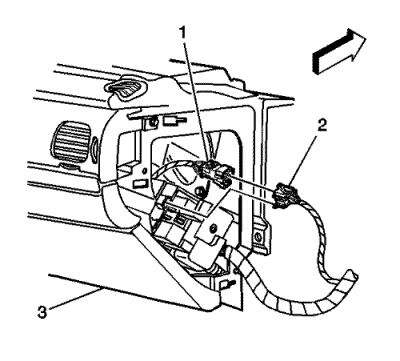
- Disconnect the instrument panel air bag yellow harness connector (1) from the vehicle harness connector (2).
Note: If the vehicle is equipped with dual stage air bags the steering wheel air bag and instrument panel air bag will each have 4 wires. Refer to Component Connector End Views for determining high and low circuits.
- Cut the yellow harness connector out of the vehicle, leaving at least 16 cm (6 in) of wire at the connector.
- Strip 13 mm (0.5 in) of insulation from each of the connector wire leads.
- Cut two 6.1 m (20 ft) deployment wires from a 0.8 mm (18 gauge) or thicker multi-strand wire. These wires will be used to fabricate the passenger deployment harness.
- Strip 13 mm (0.5 in) of insulation from both ends of the wires.
- Twist together one end from each of the wires in order to short the wires.
- Twist together the 2 connector wire leads from the high circuits from both stages of the instrument panel air bag to one set of deployment wires. Refer to Component Connector End Views in order to determine the correct circuits.
- Inspect that the 3-wire connection is secure.
- Secure and insulate the 3-wire connection to the deployment harness using electrical tape.
- Twist together the 2 connector wire leads from the low circuits from both stages of the instrument panel air bag to one set of deployment wires. Refer to Component Connector End Views in order to determine the correct circuits.
- Inspect that the 3-wire connection is secure.
- Secure and insulate the 3-wire connection to the deployment harness using electrical tape.
- Connect the deployment harness to the instrument panel air bag in-line connector.
- Route the deployment harness out of the passenger side of the vehicle.
- Disconnect the yellow harness connector to the right roof rail air bag from the vehicle harness connector.
- Cut the harness connector out of the vehicle, leaving at least 16 cm (6 in) of wire at the connector.
- Strip 13 mm (0.5 in) of insulation from each of the connector wire leads.
- Cut two 6.1 m (20 ft) deployment wires from a 0.8 mm (18 gauge) or thicker multi-strand wire. These wires will be used to fabricate the roof rail air bag deployment harness.
- Strip 13 mm (0.5 in) of insulation from both ends of the wires.
- Twist together one end from each of the wires in order to short the wires.
- Twist together one connector wire lead to one deployment wire.
- Secure and insulate the connection using electrical tape.
- Twist together and tape the remaining connector wire lead to the remaining deployment wire.
- Connect the deployment harness to the roof rail air bag yellow connector.
- Route the deployment harness out of the passenger side of the vehicle.
- Completely cover the windscreen and the front door window openings with a drop cloth.
- Stretch to the full length all of the deployment harness wires on the right side of the vehicle.
- Deploy each deployment loop one at a time.
- Place a power source, 12 V minimum/2A minimum, such as a vehicle battery, near the shorted end of the harnesses.
- Separate one set of wires and touch the wire ends to the power source in order to deploy the selected air bag.
- Disconnect the deployment harness from the power source and twist the wire ends together.
- Continue the same process with the remaining deployment harnesses.
- Disconnect all harnesses from the vehicle.
- Discard the harnesses.
- Scrap the vehicle in the same manner as a non-SIR equipped vehicle.
- If one or all of the air bags did not deploy, remove the undeployed air bags from the vehicle.
| ©© Copyright Chevrolet. All rights reserved |


