Heater Inlet And Outlet Pipe Replacement
Special Tools
BO-38185 Hose Clamp Pliers
For equivalent regional tools, refer to Special Tools .
Removal Procedure
Danger: Always perform the High Voltage Disabling procedure prior to servicing any High Voltage component or connection. Personal Protection Equipment (PPE) and proper procedures must be followed.
The High Voltage Disabling procedure will perform the following tasks:
| • | Identify how to disable high voltage. |
| • | Identify how to test for the presence of high voltage. |
| • | Identify conditions under which high voltage is always present and personal protection equipment (PPE) and proper procedures must be followed. |
- Disable the high voltage system. Refer to High Voltage Disabling .
- Disconnect the battery negative cable. Refer to Battery Negative Cable Disconnection and Connection .
Note: Replace corroded hose clamps and brackets.
- Drain the cooling system. Refer to Cooling System Draining and Filling .
- Remove the front wheelhouse front liner on passenger side. Refer to Front Wheelhouse Front Liner Replacement .
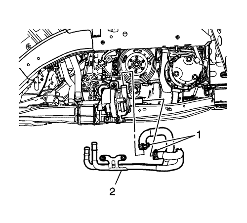
- Remove the heater inlet and outlet pipe clamps (1) at heater water auxiliary pump using BO-38185 pliers .
- Remove the heater inlet and outlet pipe (2) from the heater water auxiliary pump.
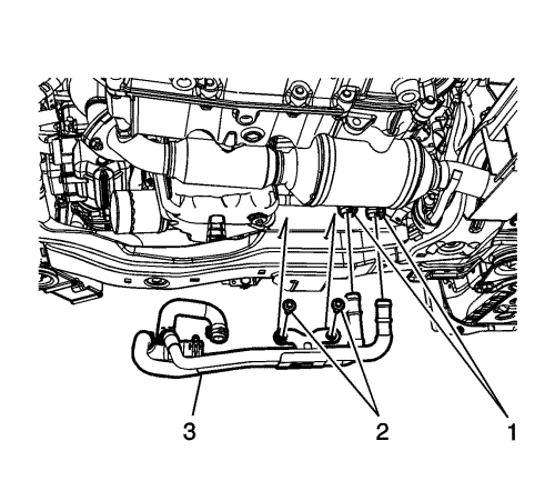
- Remove the heater inlet and outlet pipe clamps (1) at the heater water auxiliary pump inlet hose and the heater outlet hose using BO-38185 pliers .
- Remove the heater inlet and outlet pipe bolts (2) from the cradle.
- Remove the heater inlet and outlet pipe (3) from the vehicle.
Installation Procedure
- Install the heater inlet and outlet pipe (3) to the vehicle.
Caution: Refer to Fastener Caution in the Preface section.
- Install the heater inlet and outlet pipe bolts (2) to the cradle and torque to 17 N·m (13 lb ft).
- Install the heater inlet and outlet pipe clamps (1) at the heater water auxiliary pump inlet hose and the heater outlet hose using BO-38185 pliers .
- Install the heater inlet and outlet pipe (2) to the heater water auxiliary pump.
- Install the heater inlet and outlet pipe clamps (1) at the heater water auxiliary pump using BO-38185 pliers .
- Install the front wheelhouse front liner on passenger side. Refer to Front Wheelhouse Front Liner Replacement .
- Fill the cooling system. Refer to Cooling System Draining and Filling .
- Connect the battery negative cable. Refer to Battery Negative Cable Disconnection and Connection .
- Enable the high voltage system. Refer to High Voltage Enabling .
| ©© Copyright Chevrolet. All rights reserved |


