Quarter Outer Panel Sectioning
Danger: Always perform the High Voltage Disabling procedure prior to servicing any High Voltage component or connection. Personal Protection Equipment (PPE) and proper procedures must be followed.
The High Voltage Disabling procedure will perform the following tasks:
| • | Identify how to disable high voltage. |
| • | Identify how to test for the presence of high voltage. |
| • | Identify condition under which high voltage is always present and personal protection equipment (PPE) and proper procedures must be followed. |
| • | Safety glasses with appropriate side shields when within 15 meters (50 feet) of the vehicle, either indoors or outdoors. |
| • | Certified and up-to-date Class "0" Insulation gloves rated at 1000V with leather protectors. |
| - | Visually and functionally inspect the gloves before use. |
| - | Wear the Insulation gloves with leather protectors at all times when working with the high voltage battery assembly, whether the system is energised or not. |
Special Tools
| • | BO-6392 Flanging Tool Kit |
For equivalent regional tools, refer to Special Tools .
Removal Procedure
Warning : Refer to Approved Equipment for Collision Repair Warning in the Preface section.
Warning : Refer to Collision Sectioning Warning in the Preface section.
Warning : Refer to Glass and Sheet Metal Handling Warning in the Preface section.
- Disable the SIR system. Refer to SIR Disabling and Enabling .
- Inspect the high voltage system. Refer to High Voltage System Inspection .
- Disable the high voltage system. Refer to High Voltage Disabling .
- Remove all related panels and components.
- Visually inspect the damage. Repair as much of the damage as possible.
- Remove the sealers and anti-corrosion materials from the repair area as necessary.
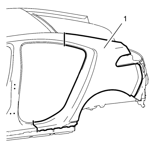
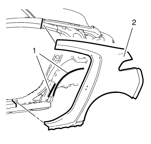
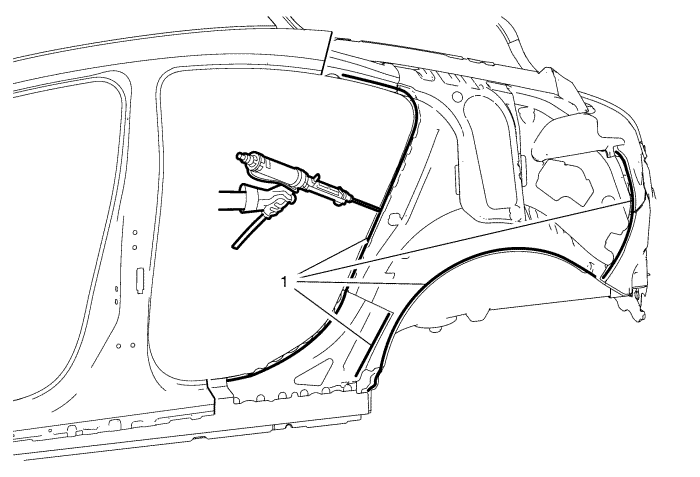
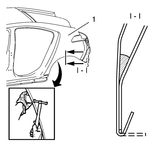
- Create cut lines on the quarter outer panel (1).
Note : Do not damage any inner panels or reinforcements.
- Cut the quarter outer panel (1) where the sectioning is to be performed.
- Locate and mark all the necessary factory welds of the quarter outer panel (1).
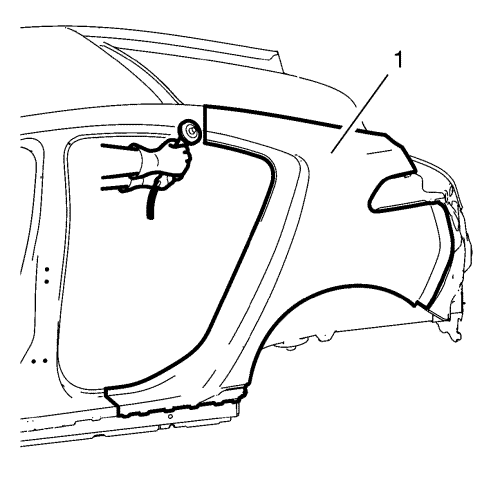
- Drill all factory welds. Note the number and location of welds for installation of the service assembly.
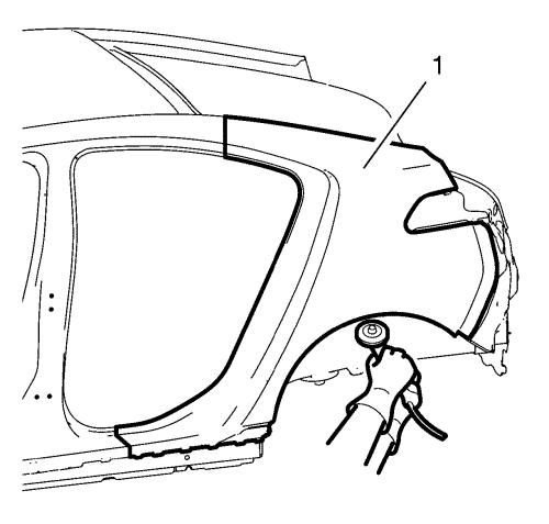
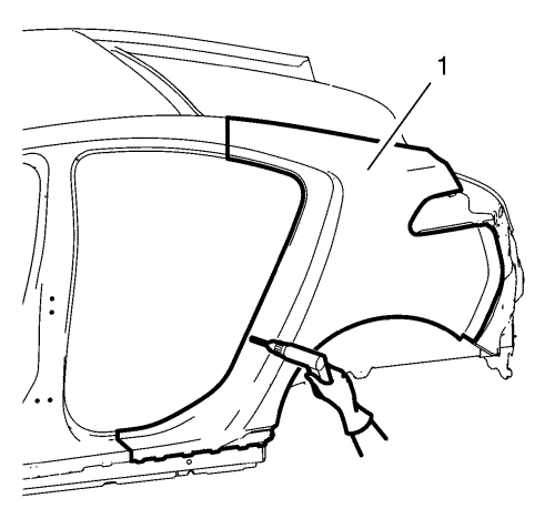
- Open the wheelhouse flanging of the quarter outer panel (1).
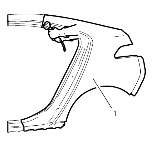
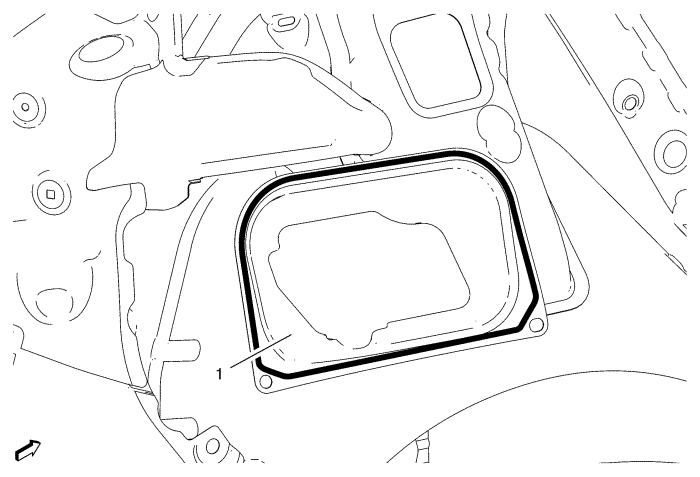
- To remove the damaged quarter outer panel (2) cut the adhesive (1) with a suitable tool.
Installation Procedure
- Cut the quarter outer panel (1) in corresponding locations to fit the remaining original panel. The sectioning joint should be trimmed to allow a gap of one-and-one-half-times the metal thickness at the sectioning joint.
- Prepare all mating surfaces as necessary.
- Clean and prepare the attaching surfaces for spot welding.
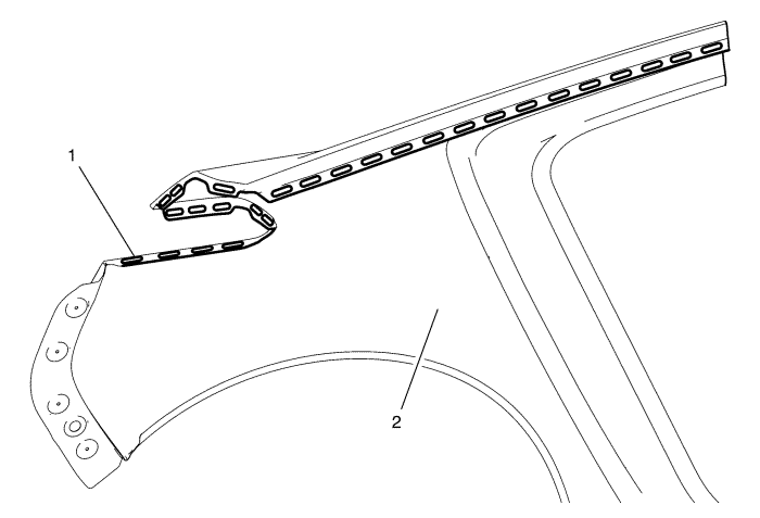
- Create 27 5 x 18 mm (4/16 x 11/16 in) (1) slots for MIG-brazing to the quarter outer panel (2).
- Position the quarter outer panel on the vehicle.
- Verify the fit of the quarter outer panel.
- Clamp the quarter outer panel into position.
- Drill 8 4,2 mm holes (1) for rivets to quarter outer panel (2).
- Remove quarter outer panel from the vehicle.
- Apply structural adhesive to body side inner panel (1).
- Apply structural adhesive to body side inner panel filler (1) on right side ONLY.
- Position the quarter outer panel (1) on the vehicle.
- Verify the fit of the quarter outer panel.
- Clamp the quarter outer panel into position.
- Rivet (2) the quarter outer panel.
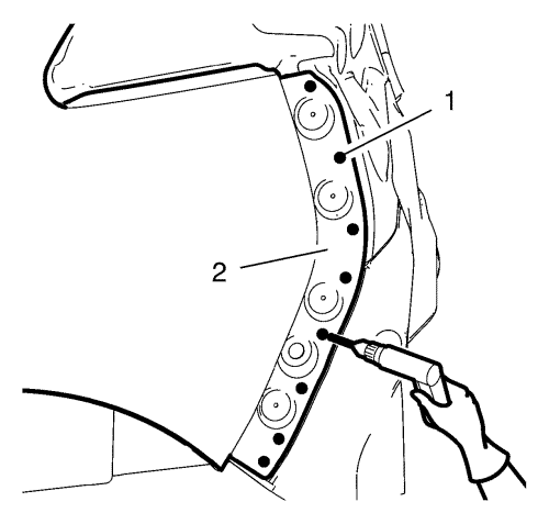
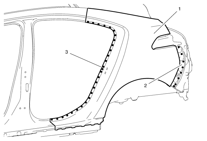
- Spot weld the quarter outer panel (1) accordingly.
Flange rear side door opening (3) - 28 spot welds.
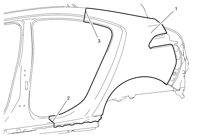
- Braze the quarter outer panel (1) accordingly.
| • | Quarter outer panel / rocker outer panel (2) - 160 mm. |
| • | Quarter outer panel / body side outer upper panel (3) - 215 mm. |
| • | Quarter outer panel / body side inner panel - 27 5 x 18 mm (4/16 x 11/16 in) slot brazes. |
- To create a solid braze with minimum heat distortion, make 25 mm stitch brazes along the seam with 25 mm gaps between them. Then go back and complete the stitch braze.
- Pre-flanging the flange with BO-6396 pliers and BO-6392 tool kit.
- Finish closing the wheelhouse flanging.
- Apply the sealers and anti-corrosion materials to the repair area, as necessary.
- Paint the repaired area.
- Install all related panels and components.
- Enable the high voltage system. Refer to High Voltage Enabling .
- Enable the SIR system. Refer to SIR Disabling and Enabling .
| ©© Copyright Chevrolet. All rights reserved |


