Instrument Panel Wiring Harness Replacement
Removal Procedure
Note: Arrange a place to embed the removed parts.
- Install the MDI, start the ignition and read the diagnostic trouble codes.
| 1.1. | Delete all diagnostic trouble codes and read diagnostic trouble codes again. |
| 1.2. | Notice ALL diagnostic trouble codes. |
- Disconnect the battery negative cable. Refer to Battery Negative Cable Disconnection and Connection .
- Remove the inner and outer instrument panel lower trim pad retainer. Refer to
Lower Trim Pad Retainer Replacement : Outer → Inner .
- Remove the communication interface module. Refer to Communication Interface Module Replacement .
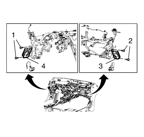
- Remove the fasteners (1, 2), then remove the left and right instrument panel electrical centre assembly (3, 4).
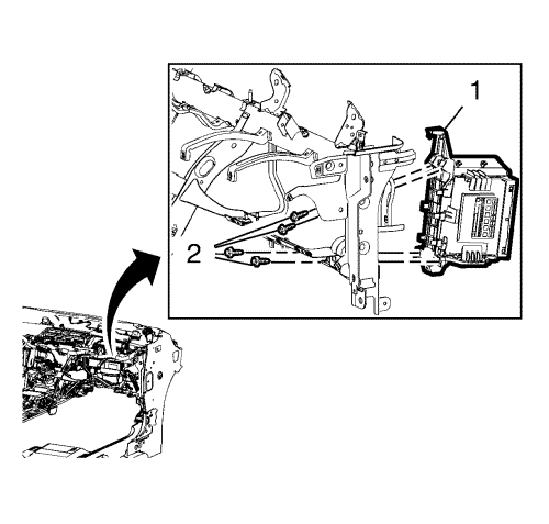
- Remove the fasteners (2), than remove the communication interface module bracket (1).
- Release all mass cables from the tie bar and body weld studs.
- Release the instrument panel wiring harness. Take pictures from the routing and fixing points of the instrument panel wiring harness for the orientation.
- Disconnect all electrical connectors and unscrew ground cables.
| 9.1. | Release all fixations. |
| 9.2. | Take care about destroyed cable straps and harness guidance regarding noises and rattles. |
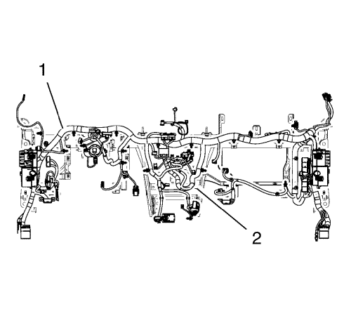
- Remove the instrument panel wiring harness (1) from the instrument panel tie bar (2) and lay it on the floor. Unpack the new instrument panel wiring harness and compare the old with the new harness concerning quantity of fixing points, cable straps, guides, part numbers and pin assignments.
Installation Procedure
- After comparing the new with the old harness (1) install the harness on the tie bar (2).
| • | Check if there is no twisting and bending and fix the new wiring harness. |
| • | Use new cable straps and pins. Connect all electrical connectors. |
| • | Take care for the correct counterpart and the pin assignment. |
| • | Use the pictures for orientation. |
Caution: Refer to Fastener Caution in the Preface section.
- Tighten all mass cables to the weld studs to9 N·m (80 lb in).
- Install the communication interface module bracket (1) and tighten the fasteners (2) to 2.5 N·m (22 lb in).
- Install the left and right instrument panel electrical centre assembly (3, 4) and tighten the fasteners (1, 2) to 2.5 N·m (22 lb in).
- Install the communication interface module. Refer to Communication Interface Module Replacement .
- Install the inner and outer instrument panel lower trim pad retainer. Refer to
Lower Trim Pad Retainer Replacement : Outer → Inner .
- Connect the battery negative cable. Refer to Battery Negative Cable Disconnection and Connection .
- Install the MDI, start the ignition and read the diagnostic trouble codes. Delete all diagnostic trouble codes and read trouble codes again.
- Check all electrical functions and perform a test run.
| ©© Copyright Chevrolet. All rights reserved |


