Front End Upper Tie Bar Support Replacement
Removal Procedure
Warning : Refer to Approved Equipment for Collision Repair Warning in the Preface section.
Warning : Refer to Glass and Sheet Metal Handling Warning in the Preface section.
- Disable the SIR system. Refer to SIR Disabling and Enabling .
Danger: Always perform the High Voltage Disabling procedure prior to servicing any High Voltage component or connection. Personal Protection Equipment (PPE) and proper procedures must be followed.
The High Voltage Disabling procedure will perform the following tasks:
| • | Identify how to disable high voltage. |
| • | Identify how to test for the presence of high voltage. |
| • | Identify condition under which high voltage is always present and personal protection equipment (PPE) and proper procedures must be followed. |
- Disable the high voltage system. Refer to High Voltage Disabling .
- Remove all related panels and components.
- Visually inspect the damage. Repair as much of the damage as possible.
- Remove the sealers and anti-corrosion materials from the repair area as necessary.
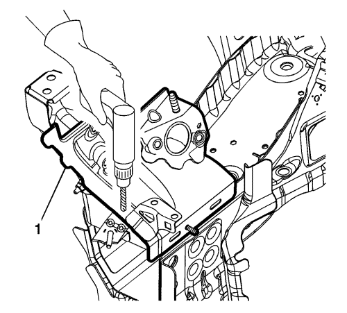
- Locate and mark all the necessary factory welds of the front end sheet metal cross panel reinforcement (1).
- Drill and grind all factory welds. Note the number and location of welds for installation of the service assembly.
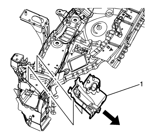
- Remove the front end sheet metal cross panel reinforcement (1).
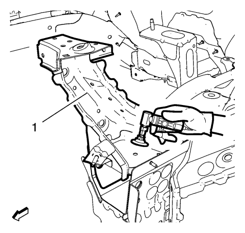
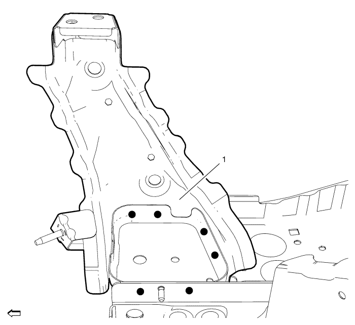
- Grind the factory welds of the front end upper tie bar support (1) from the inside.
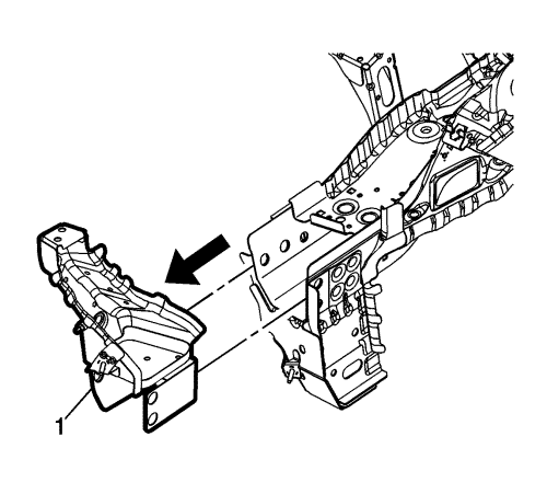
- Remove the front end upper tie bar support (1).
Installation Procedure
- Prepare all mating surfaces as necessary.
- Clean and prepare the attaching surfaces for spot welding and brazing.
- Position the front end upper tie bar support (1) on the vehicle.
- Verify the fit of the front end upper tie bar support.
- Clamp the front end upper tie bar support into position.
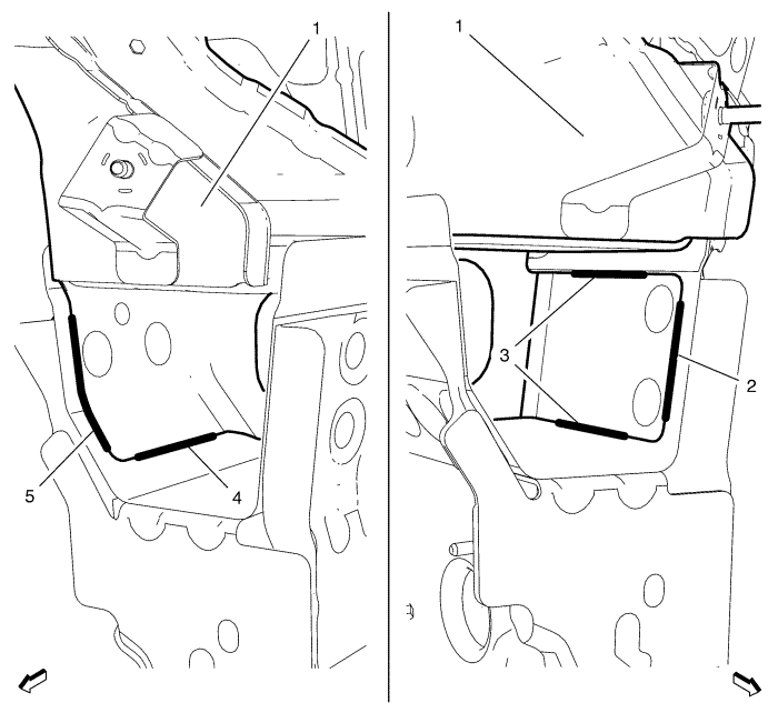
- Braze the front end upper tie bar support - left side (1) accordingly.
| 6.1. | Brace line (2) - 50 mm |
| 6.2. | Brace line (3) - 70 mm |
| 6.3. | Brace line (4) - 60 mm |
| 6.4. | Brace line (5) - 60 mm |
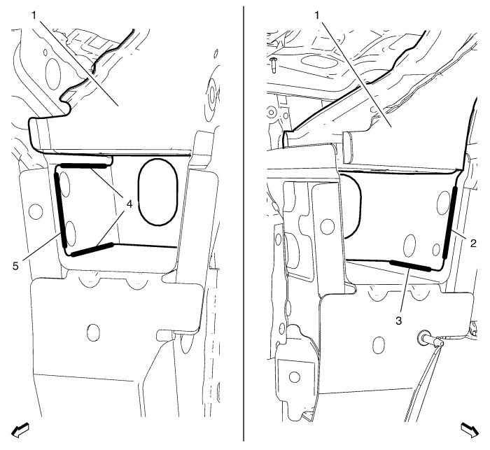
- Braze the front end upper tie bar support - right side (1) accordingly.
| 7.1. | Brace line (2) - 60 mm |
| 7.2. | Brace line (3) - 60 mm |
| 7.3. | Brace line (4) - 70 mm |
| 7.4. | Brace line (5) - 50 mm |
- Spot weld the front end upper tie bar support (1) with 6 spot welds accordingly.
- Position the front end sheet metal cross panel reinforcement (1) on the vehicle.
- Verify the fit of the front end sheet metal cross panel reinforcement.
- Clamp the front end sheet metal cross panel reinforcement into position.
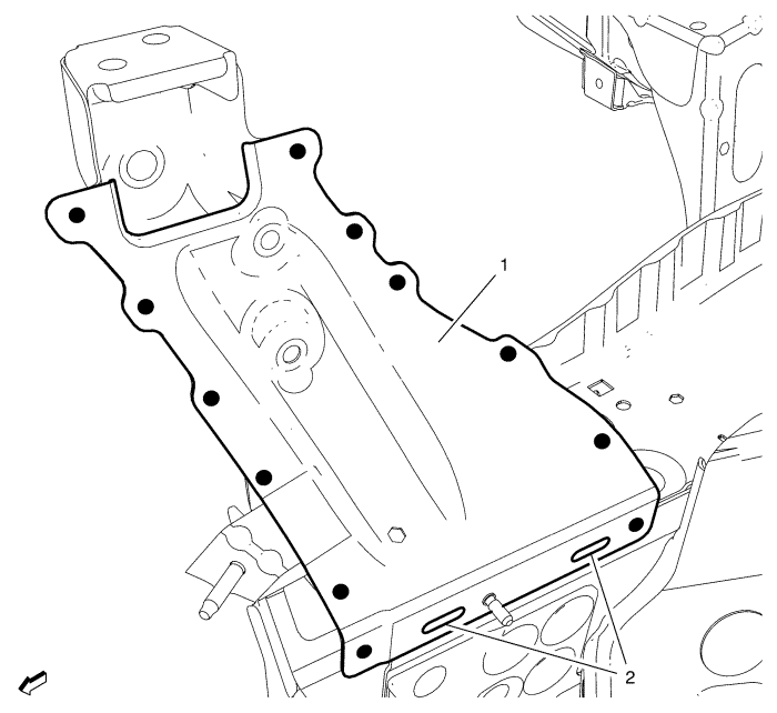
- Spot weld the front end sheet metal cross panel reinforcement (1) with 12 spot welds accordingly.
- Use the factory slots (2) for brazing.
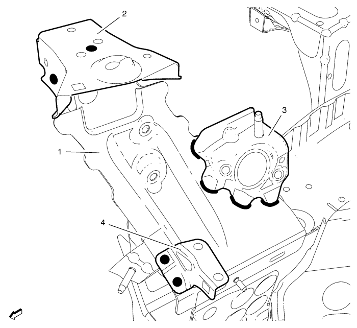
- Install the brackets.
| 14.1. | Bonnet front bumper bracket (2) - 3 spot welds. |
| | Note: This applies to the left side ONLY. |
| 14.2. | Drive motor power inverter bracket (3) - 4 10 mm braze edge seams |
| 14.3. | Headlamp bracket (4) - 2 spot welds. |
- Apply the sealers and anti-corrosion materials to the repair area as necessary.
- Paint the repaired area.
- Install all related panels and components.
- Enable the high voltage system. Refer to High Voltage Enabling .
- Enable the SIR system. Refer to SIR Disabling and Enabling .
| ©© Copyright Chevrolet. All rights reserved |


