SECTION
DIAGNOSIS
Engine Diagnosis
Reviewing the description and operation information provided will assist in determining whether the condition described by the customer is a fault or normal engine operation.
Symptoms
Strategy Based Diagnosis
- Review the system operations to familiarise yourself with the system functions, refer to 1A1General Engine Information-2.0Diesel Section 1A1, General Engine Information - 2.0Dieseland Section 1F1, Engine Control - 2.0 Diesel – General Information.
- Perform an engine management Diagnostic System Check, refer to Section 1F1 Engine Control - 2.0 Diesel – Diagnostics.
All diagnosis on a vehicle should follow a logical process. Strategy based diagnosis is a uniform approach for repairing all vehicle systems. The strategy based diagnostic flow chart may always be used to resolve a system problem. The diagnostic flow chart is the place to start when repairs are required. For a detailed explanation of strategy based diagnosis and the flow chart, refer to
Section 1F1 Engine Control - 2.0 Diesel – Diagnostics.Visual / Physical Inspection
- Inspect the vehicle for aftermarket accessories which may adversely affect engine operation.
- Inspect the easily accessible or visible system components for obvious signs of damage or conditions that may cause the symptom.
- Check the engine lubrication system for the following :
- correct oil level,
- correct lubricant viscosity,
- correct oil filter application, and
- contaminated or burnt oil.
- Confirm the exact operating conditions under which the fault occurs. Note factors such as :
- engine speed (r.p.m.),
- ambient temperature,
- engine temperature,
- engine warm-up time, and
- vehicle road speed.
- Compare the engine sounds, if applicable, to a known good engine, and ensure you are not trying to diagnose a normal operating condition.
Intermittent
For intermittent faults, test the vehicle under the same conditions the customer reported in order to confirm whether the system is operating correctly.
Compression Test
Caution : To not engine start, disconnect the CKP(Crankshaft Position Sensor) connector. But do not remove the fuel pump fuse in the fuse box or disconnect the high pressure pump connector to not engine start. Because the high pressure pump is lubricated by a fuel and the fuel pump, if you remove the fuel pump fuse or disconnect the high pressure pump connector, the high pressure pump will be damaged.Test the compression pressure for each cylinder. Low compression pressure may be the fault of the valves or the pistons. The following conditions should be considered when you check the cylinder compression :
- The engine should be at normal operating temperature.
- The battery must be at or near full charge.
- The engine cranking time for compression test should be less than 10 seconds at interval of 30 seconds.
- Disconnect the CKP (Crankshaft Position Sensor) connector.
- Remove the fuel pump relay from the engine room fuse box.
- Remove No.1 injector from the cylinder head.
- Crank the engine with the start motor to remove a foreign substance in the cylinder within 5 seconds.
- Install the compression pressure gauge in (EN-48248) the injector hole for the cylinder that is being checked.
Notice : They are same configuration between the compression pressure gauge and the injector. So, the installation procedure of the compression pressure gauge is same way that of the injector. Refer to Section 2F1, Engine Controls. Section 1F2, Engine Controls. - Using the vehicle's starter motor, rotate or crank the engine for less than 10 seconds at interval of 30 seconds.
Caution : While compression pressure testing for the cylinder that is being checked, it may result of fuel leaking out from fuel pipes injector side. So, to not drop fuel on the engine cover from the fuel pipes, put something like vessels.
- The compression pressure gauge reading should be normally 2600 kPa (377 psi) for any of the cylinders. The maximm pressure difference between each cylinder is about 10 %.
- Examine the gauge readings obtained after the four "puffs" per cylinder are obtained from cranking the starter motor. The readings are explained in the following descriptions :
- Normal Condition : Compression builds up quickly and evenly to the specified compression on each cylinder.
- Piston Rings Faulty : Compression is low on the first stroke and tends to build up on following strokes, but the compression pressure does not reach normal. The compression pressure improves considerably with the addition of oil into the cylinder.
- Valves Faulty : Low compression pressure on the first stroke. The compression pressure does not tend to build up on the following strokes. The compression pressure does not improve much with the addition of oil into the cylinder.
- Repect the above procedure No.1 to No.7 in the rest cylinders.
Oil Pressure Test
| Step | Action | Value(s) | Yes | No |
| 1 | Is the oil pressure warning lamp on? | - | Go to Step 2 | System OK |
| 2 | Check the oil level in the crankcase. Is the oil level low? | - | Go to Step 3 | Go to Step 4 |
| 3 | Add oil so that the oil level is up to the full mark on the indicator. Is the repair complete? | - | Go to Step 1 | - |
| 4 | Check the idle speed. Is the idle speed below the specified value ? | 840 ± 20 rpm | Go to Step 5 | Go to Step 6 |
| 5 | Increase the idle speed. Is the speed increased? | - | Go to Step 1 | - |
| 6 | Inspect the oil pressure switch. Is the oil pressure switch incorrect or malfunctioning? | - | Go to Step 7 | Go to Step 8 |
| 7 | Install a new oil pressure switch. Is the repair complete? | - | Go to Step 1 | - |
| 8 | Inspect the oil pressure gauge. Is the oil pressure gauge incorrect or malfunctioning? | - | Go to Step 9 | Go to Step 10 |
| 9 | Install a new oil pressure gauge. Is the repair complete? | - | Go to Step 1 | - |
| 10 | Inspect the engine oil. Is the engine oil in the crankcase diluted or of the improper viscosity? | - | Go to Step 11 | Go to Step 12 |
| 11 | Install new engine oil of the proper viscosity for the expected temperatures. Is the repair complete? | - | Go to Step 1 | - |
| 12 | Inspect the oil pump. Is the pump worn or dirty? | - | Go to Step 13 | Go to Step 14 |
| 13 | Replace the oil pump. Is the repair complete? | - | Go to Step 1 | - |
| 14 | Inspect the oil filter. Is the oil filter plugged? | - | Go to Step 15 | Go to Step 16 |
| 15 | Install a new oil filter. Is the repair complete? | - | Go to Step 1 | - |
| 16 | Inspect the oil pickup screen. Is the oil pickup screen loose or plugged? | - | Go to Step 17 | Go to Step 18 |
| 17 | Tighten or replace the oil pickup screen, as necessary. Is the repair complete? | - | Go to Step 1 | - |
| 18 | Inspect the oil pickup tube. Are there any holes in the oil pickup tube? | - | Go to Step 19 | Go to Step 20 |
| 19 | Replace the oil pickup tube. Is the repair complete? | - | Go to Step 1 | - |
| 20 | Inspect the bearing clearances. Are the bearing clearances more than the specified values? | Crankshaft Journal Bearing Oil Clearance 0.024 ~ 0.042 mm (0.00094 ~ 0.00115 in) | Go to Step 21 | Go to Step 22 |
| 21 | Replace the bearing, if necessary. Is the repair complete? | - | Go to Step 1 | - |
| 22 | Inspect the oil galleries. Are the oil galleries cracked, porous, or plugged? | - | Go to Step 23 | Go to Step 24 |
| 23 | Repair or replace the engine block. Is the repair complete? | - | Go to Step 1 | - |
| 24 | Inspect the gallery plugs. Are any of the gallery plugs missing or installed improperly? | - | Go to Step 25 | Go to Step 26 |
| 25 | Install the plugs or repair, as necessary. Is the repair complete? | - | Go to Step 1 | - |
| 26 | Inspect the camshaft. Is the camshaft worn or is there evidence of poor machining? | - | Go to Step 27 | System OK |
| 27 | Replace the camshaft. Is the repair complete? | - | Go to Step 1 | - |
Oil Leak Diagnosis
Most fluid oil leaks are easily located and repaired byvisually finding the leak and replacing or repairing thenecessary parts. On some occasions, a fluid leak maybe difficult to locate or repair. The following proceduresmay help you in locating and repairing most leaks.
Finding the Leak:
- Identify the fluid. Determine whether it is engine oil,automatic transmission fluid, power steering fluid, etc.
- Identify where the fluid is leaking from.
- After running the vehicle at normal operatingtemperature, park the vehicle over a largesheet of paper.
- Wait a few minutes.
- Find the approximate location of the leak bythe drippings on the paper.
- Visually check around the suspected component.Check around all the gasket mating surfaces forleaks. A mirror is useful for finding leaks in areas thatare hard to reach.
- If the leak still cannot be found, it may be necessary toclean the suspected area with a degreaser, steam, orspray solvent.
- Thoroughly clean the area.
- Dry the area.
- Operate the vehicle for several miles at normaloperating temperature and varying speeds.
- After operating the vehicle, visually check thesuspected component.
- If you still cannot locate the leak, try using thepowder or black light and dye method.
Powder Method:
- Clean the suspected area.
- Apply an aerosol-type powder, (such as foot powder),to the suspected area.
- Operate the vehicle under normal operating conditions.
- Visually inspect the suspected component. Trace theleak path over the white powder surface to the source.
Black Light and Dye Method:
A dye and light kit is available for finding leaks. Refer tothe manufacturer's directions when using the kit.
- Pour the specified amount of dye into the engine oil filltube.
- Operate the vehicle under normal operating conditionsas directed in the kit.
- Direct the light toward the suspected area. The dyedfluid will appear as a yellow path leading to thesource.
Repairing the Leak
Once the origin of the leak has been pinpointed andtraced back to its source, the cause of the leak must bedetermined in order for it to be repaired properly. If agasket is replaced, but the sealing flange is bent, thenew gasket will not repair the leak. The bent flange mustbe repaired also. Before attempting to repair a leak,check for the following conditions and correct them asthey may cause a leak.
Gaskets:
- The fluid level/pressure is too high.
- The crankcase ventilation system is malfunctioning.
- The fasteners are improperly tightened or the threadsare dirty or damaged.
- The flanges or the sealing surface is warped.
- There are scratches, burrs or other damage to thesealing surface.
- The gasket is damaged or worn.
- There is cracking or porosity of the component.
- An improper seal was used, (where applicable).
Seals:
- The fluid level/pressure is too high.
- The crankcase ventilation system is malfunctioning.
- The seal bore is damaged, scratched, burred ornicked.
- The seal is damaged or worn.
- Improper installation is evident.
- There are cracks in the component.
- The shaft surface is scratched, nicked or damaged.
- A loose or worn bearing is causing excess seal wear.
Base Engine Misfire without Internal Engine Noises
Condition | Action |
Abnormalities (severe cracking, bumps or missing areas) in the accessory drive belt. Also worn, damaged, or misaligned accessory drive components or excessive pulley runout. | Abnormalities in the accessory drive belt and/or components may cause engine RPM variations, noises similar to a faulty lower engine and also lead to a misfire condition. A misfire code may be present without an actual misfire condition. - Inspect the accessory drive components.
- Repair or replace all damaged components.
|
Loose and/or damaged crankshaft pulley | A misfire code may be present without an actual misfire condition. - Inspect crankshaft pulley and pulley bolt.
- Repair or replace all damaged components.
|
Loose torque converter bolts | A misfire code may be present without an actual misfire condition. - Inspect torque converter bolts and flywheel.
- Repair or replace all damaged components.
|
Loose and/or damaged flywheel | A misfire code may be present without an actual misfire condition. - Inspect flywheel and flywheel attaching bolts.
- Repair or replace all damaged components.
|
Restricted exhaust system | A severe restriction in the exhaust flow can cause significant loss of engine performance and may set a misfire code. Possible causes of restrictions include collapsed or dented pipes, plugged mufflers and/or catalytic converters. Repair or replace all damaged components. |
Air in fuel system | - Inspect fuel filter, fuel system for leaks and/or restrictions.
- Repair or replace all damaged components.
|
Bent and/or worn valve bridge and finger-follower. | - Inspect valve bridge and valve finger-follower.
- Repair or replace all damaged components.
|
Sticking valve | Carbon on the valve stem or valve seat may cause the valve to stick. - Inspect valves and valve guides.
- Repair or replace all damaged components.
|
Damaged or misaligned timing gears | - Inspect timing gears.
- Replace all damaged components.
|
Worn or faulty camshaft lobes | - Inspect camshaft lobes.
- Repair or replace all damaged components.
|
Excessive piston-to-cylinder bore clearance | - Perform compression tests.
- Inspect the piston, piston rings and cylinder bore.
- Repair or replace all damaged components.
|
Faulty cylinder head gaskets and/or cracking or other damage to the cylinder heads and engine block cooling system passages. (Coolant consumption may or may not cause the engine to overheat.) | - Perform compression tests.
- Inspect the piston, piston rings and cylinder bore.
- Repair or replace all damaged components.
|
Base Engine Misfire with Abnormal Internal Lower Engine Noises
Condition | Action |
Abnormalities (severe cracking, bumps or missing areas) in the accessory drive belt. | Abnormalities in the accessory drive belt and/or components may cause engine RPM variations, noises similar to a faulty lower engine and also lead to a misfire condition. A misfire code may be present without an actual misfire condition. - Inspect the accessory drive components.
- Repair or replace all damaged components.
|
Worn, damaged, or misaligned accessory drive components or excessive pulley runout | A misfire code may be present without an actual misfire condition. - Inspect the accessory drive components.
- Repair or replace all damaged components.
|
Loose and/or damaged crankshaft pulley | A misfire code may be present without an actual misfire condition. - Inspect crankshaft pulley and pulley bolt.
- Repair or replace all damaged components.
|
Loose torque converter bolts | A misfire code may be present without an actual misfire condition. - Inspect torque converter bolts and flywheel.
- Repair or replace all damaged components.
|
Loose and/or damaged flywheel | A misfire code may be present without an actual misfire condition. - Inspect flywheel and flywheel attaching bolts.
- Repair or replace all damaged components.
|
Excessive piston-to-cylinder bore clearance | - Perform cylinder leak down and compression tests
- Inspect the piston, piston rings and cylinder bore.
- Repair or replace all damaged components.
|
Excessive crankshaft thrust bearing clearance | Severely worn thrust surfaces on the crankshaft and/or thrust bearing may permit for and aft movement of the crankshaft and create a misfire code without an actual misfire condition. - Inspect the crankshaft end play and crankshaft thrust bearings.
- Repair or replace all damaged components.
|
Base Engine Misfire with Abnormal Valve Train Noise
Condition | Action |
Loose, worn or damaged valve bridge and finger-follower | - Inspect valve bridge and finger-follower.
- Repair or replace all damaged components.
|
Broken valve springs | - Inspect valve springs.
- Repair or replace all damaged components.
|
Sticking valve | Carbon on the valve stem or valve seat may cause the valve to stick. - Inspect valves and valve guides.
- Repair or replace all damaged components.
|
Worn or faulty camshaft lobes | - Inspect camshaft lobes.
- Repair or replace all damaged components.
|
Base Engine Misfire with Coolant Consumption
Inspection | Action |
Definition : Base engine misfire with coolant consumption |
Preliminary Inspection | |
Isolate Affected Cylinders | - Cylinder balance test with scan tool
- Cooling system pressurization
- Inspection of glow plugs
- Compression test
|
EGR System Inspection | - Inspect EGR valve and intake system for evidence of coolant leakage.
- Replace the EGR cooler if any problem is found.
|
Cylinder Head Gasket Leakage | - Remove cylinder heads of the affected cylinder bank and inspect for damage.
- Replace components as necessary.
|
Cylinder Head or Engine Block Damage | - Inspect the cylinder heads for cracks.
- Inspect the cylinder block for damage.
- Inspect the cylinder block to head mating surface for staightness.
- Replace components as necessary.
|
Base Engine Misfire with Excessive Oil Consumption
Condition | Action |
Worn valve guides | - Inspect the valves and valve guides.
- Repair or replace all damaged components.
|
Worn valve stem oil seals | - Inspect the valve stem oil seals.
- Repair or replace all damaged components.
|
Excessive piston-to-cylinder bore clearance | - Perform compression tests to determine the cause.
- Inspect the piston rings for low ring tension, broken or worn rings.
- Inspect cylinder bore.
- Repair or replace all damaged components.
|
Engine Noise on Start-Up, but Only Lasting a Few Seconds
Condition | Action |
Incorrect oil viscosity | - Drain the oil.
- Install the correct viscosity oil.
|
Excessive piston-to-cylinder bore clearance | - Inspect the piston and piston skirt, connecting rod, and cylinder bore.
- Repair or replace all damaged components.
|
Upper Engine Noise, Regardless of Engine Speed
Condition | Action |
Low oil pressure | Insufficient or poor oil supply to valve train. - Perform oil pressure test.
- Repair or replace all damaged components.
|
Improper lubrication to the valve finger-follower | - Inspect valve finger-follower, valve bridge, valve finger follower lifter, oil pump and engine block oil galleries.
- Repair or replace all damaged components.
|
Worn or damaged valve finger-follower | - Inspect valve bridge and finger-follower.
- Repair or replace all damaged components.
|
Sticking valve | Carbon on the valve stem or valve seat may cause the valve to stick. - Inspect valves and valve guides.
- Repair or replace all damaged components.
|
Worn or faulty camshaft lobes | - Inspect camshaft lobes.
- If damaged replace camshaft and all valve finger-followers.
|
Damaged or misaligned timing gears | - Inspect timing gears.
- Replace all damaged components.
|
Lower Engine Noise, Regardless of Engine Speed
Condition | Action |
Worn accessory drive components (abnormalities such as severe cracking, bumps or missing areas in the accessory drive belt and/or misalignment of the system components.) | - Inspect the accessory drive components.
- Repair or replace all damaged components.
|
Low oil pressure | Insufficient or poor oil supply to crankshaft and connecting rod bearings. - Perform oil pressure test.
- Repair or replace all damaged components.
|
Leaking and/or sticking fuel injection nozzle (A stuck fuel injection nozzle can cause a noise similar to a damaged piston, rod or rod bearing.) | - Inspect the cylinder balance with scan tool to help locate the cylinder that is the source of the noise.
- If you cannot locate the cylinder that is the source of the noise, diagnose the engine for mechanical damage.
- If it has been determined that the fuel injection nozzle is causing the noise, replace the fuel injection nozzle.
|
Loose and/or damaged crankshaft pulley | - Inspect crankshaft pulley and pulley bolt.
- Repair or replace all damaged components.
|
Loose torque converter bolts | - Inspect torque converter bolts and flywheel.
- Repair or replace all damaged components.
|
Loose and/or damaged flywheel | - Inspect flywheel and flyweel attaching bolts.
- Repair or replace all damaged components.
|
Excessive piston pin-to-bore clearance | - Inspect the piston, piston pin, and the connecting rod.
- Repair or replace all damaged components.
|
Misaligned or bent connecting rod | - Inspect connecting rod and connecting rod bearings.
- Repair or replace all damaged components.
|
Excessive connecting rod bearing clearance | - Inspect the connecting rod bearings, connecting rods, crankshaft and crankshaft journals.
- Repair or replace all damaged components.
|
Excessive crankshaft bearing clearance | - Inspect the crankshaft bearings and crankshaft journals.
- Repair or replace all damaged components.
|
Engine Noise Under Load
Cause | Correction |
Low oil pressure | Insufficient or poor oil supply to components. - Perform oil pressure test.
- Repair or replace all damaged components.
|
Loose torque converter bolts | - Inspect the torque converter bolts and flywheel.
- Repair or replace all damaged components.
|
Loose and/or damaged flywheel | - Inspect the flywheel and flywheel attaching bolts.
- Repair or replace all damaged components.
|
Excessive piston-to-cylinder bore clearance | - Inspect the piston rings for low ring tension, broken or worn rings, inspect cylinder bore.
- Repair or replace all damaged components.
|
Excessive crankshaft thrust bearing clearance | - Inspect the crankshaft end play and crankshaft thrust bearings.
- Repair or replace all damaged components.
|
Excessive crankshaft bearing clearance | - Inspect the crankshaft bearings and crankshaft journals.
- Repair or replace all damaged components.
|
Engine Will Not Crank - Crankshaft Will Not Rotate
Cause | Correction |
Seized accessory drive system component | - Inspect the accessory drive system components.
- Repair or replace all damaged components.
|
Hydraulically locked cylinder - Coolant/antifreeze in cylinder
- Oil in cylinder
- Fuel in cylinder
| - Inspect for broken head gasket(s).
- Inspect for cracked engine block or cylinder head.
- Inspect for a sticking fuel injector.
|
Seized automatic transmission torque converter | - Remove the engine assembly. The torque converter bolts are not accessible with the engine installed to the transmission.
- Rotate crankshaft at the pulley.
|
Seized manual transmission | - Disengage the clutch.
- Rotate crankshaft at the pulley.
Refer to Unit Repair Manual - Manual Transmission. |
Material in cylinder : - Broken valve
- Piston material
- Foreign material
| - Inspect cylinder for damaged components and/or foreign materials.
- Repair or replace as required.
|
Seized crankshaft or connecting rod bearings | - Inspect crankshaft and connecting rod bearings. .
- Repair as required.
|
Bent or broken connecting rod | - Inspect connecting rods.
- Repair as required.
|
Broken crankshaft | - Inspect crankshaft.
- Repair as required.
|
Coolant in Combustion Chamber
Inspection | Action |
Definition : Excessive white smoke and/or coolant type odor coming from the exhaust pipe may indicate coolant in the combustion chamber. Low coolant levels, an inoperative cooling fan, or a faulty thermostat may lead to an "overtemperature" condition which may cause engine component damage. |
Preliminary Inspection | |
Isolate Affected Cylinders | - Cylinder balance test with scan tool
- Cooling system pressurization
- Compression test
|
EGR System Inspection | - Inspect EGR valve and intake system for evidence of coolant leakage.
- Replace the EGR cooler if any problem is found.
|
Cylinder Head Gasket Leakage | - Remove cylinder heads of the affected cylinder bank and inspect for damage.
- Replace components as necessary.
|
Cylinder Head or Engine Block Damage | - Inspect the cylinder heads for cracks.
- Inspect the cylinder block for damage.
- Inspect the cylinder block to head mating surface for straightness.
- Replace components as necessary.
|
Coolant in Engine Oil
Cause | Correction |
Definition : Foamy or discolored oil or an engine oil "overfill" condition may indicate coolant entering the engine crankcase. Low coolant levels, an inoperative cooling fan, or a faulty thermostat may lead to an "overtemperature" condition which may cause engine component damage. Contaminated engine oil and oil filter should be changed. - Inspect the oil for excessive foaming or an overfill condition. Oil diluted by coolant may not properly lubricate the crankshaft bearings and may lead to component damage. Refer to "Lower Engine Noise, Regardless of Engine Speed" in this section.
- Inspect by performing a Cylinder Leak-Down Test. During this test, excessive air bubbles within the cooling system may indicate a faulty gasket or damaged component.
- Inspect by performing a cylinder compression test. Two cylinders "side-by-side" on the engine block with low compression may indicate a failed cylinder head gasket. Refer to "Engine Compression Test" in this section.
|
Faulty cylinder head gasket | |
Warped cylinder head | |
Cracked cylinder head | Replace the cylinder head and gasket. |
Cracked engine block | Replace the components as required. |
Cylinder head, block, or manifold porosity | Replace the components as required. |
Leaking engine oil cooler | Replace components as required. |
Fuel in Engine Oil
Definition : If fuel is suspected of leaking into the crankcase, the following procedure should be performed to verify the condition.
- Remove the oil level indicator and allow oil to drop onto a clean white paper towel.
- If the oil is diluted with fuel, it will become apparent as the towel wicks the fuel away from the drop of oil on the towel. The fuel will expand out in a ring around the oil droplet.
- If fuel dilution is apparent, inspect the vehicle for aftermarket performance accessories that may cause damage to the injection pump. After repairs are completed, perform the test again to verify the condition is corrected.
- If no fuel dilution is present, verify the oil level and correct as needed.
Turbocharger Whine Noise
Condition | Action |
Some whine noise is normal. Compare to a known good vehicle. |
Leaking charge air cooler/pipes/hoses | Inspect for leaks in charge air cooler/pipes/hoses. |
Worn turbocharger bearings | If the turbocharger bearings are worn or damaged, repair or replace the turbocharger. |
Intake system leaks or obstructions | Inspect for leaks or obstructions in the intake manifolds. |
Turbocharger Hissing Noise
Condition | Action |
Air inlet leaks or obstructions | Inspect for leaks or obstructions in the turbocharger inlet pipes/hoses. |
Leaking charge air cooler/pipes/hoses | Inspect for leaks or obstructions in the charge air cooler/pipes/hoses. |
Leaking or restricted exhaust system | - Inspect for a leak in the exhaust system.
- Inspect for a restricted exhaust system.
|
Intake system leaks or obstructions | - Inspect for leaks in the intake manifolds.
- Inspect for obstructions in the intake manifolds.
|
Turbocharger Oil Leak from Compressor Seal
Condition | Action |
Important : Oil in the turbocharger air inlet duct, oil on the compressor wheel, and oil throughout the charge air cooler system is normal with a closed PCV system. Do not attempt repairs for this condition. |
Restricted air system | Inspect for clogged air filter element or restricted air inlet system. |
Restricted exhaust system | Inspect for a restricted exhaust. |
Leaking exhaust system. | Inspect for exhaust manifold leaks. |
Poor oil drainage from turbocharger | Inspect for restricted turbocharger oil drain pipe. |
Restricted crankcase ventilation system | Inspect for restricted crankcase ventilation system. |
Worn internal engine components | Inspect for excessive blowby or engine oil consumption. |
Turbocharger Oil Leak From Turbine Seal
Condition | Action |
Poor oil drainage from turbocharger | Inspect for a restricted turbocharger oil drain pipe. |
Restricted crankcase ventilation system | Inspect for a restricted crankcase ventilation system. |
Worn internal engine components | Inspect for excessive blowby or engine oil consumption. |
Turbocharger Lack of Oil Supply
Condition | Action |
Restricted oil supply pipe | Inspect for restricted turbocharger oil supply pipe. |
Leakage of oil at the oil supply pipe | Inspect for the turbocharger oil supply pipe |
Drive Belt Chirp
Notice : Chirping during start-up in cold damp conditions that abates once the engine reaches operating temperature is considered normal.
Diagnostic Aids
The symptom may be intermittent due to moisture on the drive belts or pulleys. It may be necessary to spray a small amount of water on the drive belt to duplicate and confirm a customers concern. If spraying water onto the drive belt system duplicates the symptom, cleaning the belt pulleys may be the solution.
A loose or incorrectly installed body component, suspension component or other item may be the cause of the noise.
Test Description
The numbers below refer to steps in the diagnostic table.
- The noise may not be engine related. This step is to confirm the engine is making the noise. If the engine is not making the noise, do not proceed further with this diagnostic procedure.
- The noise may be an internal engine noise. Removing the drive belt and operating the engine briefly will confirm whether or not the noise is related to the drive belt.
- Inspect all drive pump pulleys for pilling.
Notice : Pilling is the small balls (pills) or strings of rubber in the belt grooves caused by the accumulation of rubber dust.
- Misalignment of the accessory drive system pulleys may be caused by incorrect mounting of an accessory drive component (A/C compressor, generator etc.) or pulley. Misalignment may also be caused by incorrect installation of a pulley during a previous repair. Test for a misaligned pulley using a straight edge in the pulley grooves across two or three pulleys. If a misaligned pulley is found, refer to the relevant component service information for the correct installation and removal procedures.
- Inspecting the fasteners can eliminate the possibility that an incorrect fastener has been installed.
- Inspecting the pulleys for being bent should include inspecting for a dent or other damage that would prevent the drive belt from not seating correctly in all of the pulley grooves or on the smooth surface when the back end of the belt is used as the driving surface.
- Replacing the drive belt when it is not damaged and there is no excessive pilling will only be a temporary repair.
Diagnostic Table
Notice : Chirping during start-up in cold damp conditions that abates once the engine reaches operating temperature is considered normal.
Definition : Accessory drive belt chirping can be defined as a high-pitched noise that is heard once per revolution of the drive belt or a pulley.
| Step | Action | Value(s) | Yes | No |
| 1 | Did you review the information provided in Symptoms, and perform the required inspections. | - | Go to Step 2 | |
| 2 | Confirm the customer complaint. Is there a chirping noise? | - | Go to Step 3 | Refer to Diagnostic Aids in this Section |
| 3 | - Remove the drive belt, refer to Section 1B, Engine Mechanical – 2.0 Diesel.
- Operate the engine for no more than 40 seconds.
Does the chirping noise still exist? | - | Accessory drive system OK. Go to Symptoms, and restart the diagnosis of the noise | Go to Step 4 |
| 4 | Inspect for severe pilling, i.e. in excess of 33% of the belt groove depth. Do the belt grooves have pilling? | - | Go to Step 5 | Go to Step 6 |
| 5 | Clean the drive belt pulleys with a wire brush. Are the belt pulleys clean? | - | Go to Step 15 | Go to Step 6 |
| 6 | Inspect for misalignment of the pulleys. Are the pulleys misaligned? | - | Go to Step 7 | Go to Step 8 |
| 7 | Replace or repair misaligned pulleys. Did you complete the repair? | - | Go to Step 15 | - |
| 8 | Inspect for any bent or damaged accessory drive component mounting brackets. Did you find any bent or damaged brackets? | - | Go to Step 9 | Go to Step 10 |
| 9 | Replace or repair any bent or damaged Brackets. Did you complete the repairs? | - | Go to Step 15 | - |
| 10 | Inspect for missing, loose or incorrect fasteners. Did you find any missing, loose or incorrect fasteners? | - | Go to Step 11 | Go to Step 12 |
| 11 | Tighten any loose fasteners to the torque specification. Replace any incorrect or missing fasteners. Did you complete the repairs? | - | Go to Step 15 | - |
| 12 | Inspect for a bent pulley. Did you find any bent pulleys? | - | Go to Step 13 | Go to Step 14 |
| 13 | Replace bent pulleys as required. Did you complete the repair? | - | Go to Step 15 | - |
| 14 | Did you complete the repair? | - | Go to Step 15 | - |
| 15 | Reinstall the accessory drive belt and operate the system to confirm the repair. Did you correct the chirp noise? | - | Accessory drive system OK | |
Drive Belt Squeal
Diagnostic Aids
If the noise is intermittent, confirm the accessory drive components by varying their loads, making sure they are operated to their maximum capacity. An overcharged A/C system, restrictions in the power steering pressure circuit or a faulty generator is likely causes of accessory drive belt squeal.
A loose or incorrectly installed body component, suspension component or other item may be the cause of the noise.
Test Description
The numbers below refer to steps in the diagnostic table.
- The noise may not be engine related. This step is to confirm the engine is making the noise. If the engine is not making the noise, do not proceed further with this diagnostic procedure.
- The noise may be an internal engine noise. Removing the drive belt and operating the engine briefly will confirm whether or not the noise is related to the drive belt.
- Confirms an accessory drive component does not have a seized bearing. With the belt removed, test the bearings in the accessory drive components spin free and smooth.
- Confirms the drive belt tensioner is operating correctly. If the drive belt tensioner is not operating correctly, drive belt tension will not be maintained, resulting in a belt squealing noise.
- Confirms the belt is not too long, which would prevent the tensioner from working as intended. Also, if an excessively long belt has been fitted, it may also be routed incorrectly and may be turning an accessory drive component in the wrong direction.
- Misalignment of the pulleys may be caused by one of the following :
- Incorrect mounting of an accessory drive component,
- Incorrect installation of an accessory drive pulley or,
- Bent or damaged pulley.
- Test for a misaligned pulley using a straight edge in the pulley grooves across 2 or 3 pulleys. If a misaligned pulley is found, refer to the relevant component service information for the correct installation and removal procedures.
- This test is to confirm the pulleys are the correct diameter and/or width. Using a known good vehicle, compare the pulley sizes.
Diagnostic Table
Definition : Accessory drive belt squealing can be defined as a loud screeching noise caused by a slipping drive belt. Belt squeal is unusual in multi-rib belts. Drive belt squeal generally occurs when a heavy load is applied to the drive belt, such as an air-conditioning compressor engagement, snapping the throttle, seized pulley or a faulty accessory drive component.
| Step | Action | Value(s) | Yes | No |
| 1 | Did you review the information provided in Symptoms, and perform the required inspections. | - | Go to Step 2 | |
| 2 | Confirm the customer complaint. Is there a squealing noise? | - | Go to Step 3 | Refer to Diagnostic Aids in this Section |
| 3 | - Remove the drive belt, refer to Section 1B, Engine Mechanical – 2.0 Diesel.
- Operate the engine for no more than 40 seconds.
Does the squealing noise still exist? | - | Accessory drive system OK. Go to Symptoms, and restart the diagnosis of the noise | Go to Step 4 |
| 4 | Inspect the accessory drive components for a seized bearing and general malfunctions. Did you find and correct any seized bearings or general malfunctions in the accessory drive system? | - | Go to Step 9 | Go to Step 5 |
| 5 | Test the accessory drive belt tensioner for correct operation, refer to Drive Belt Tensioner Diagnosis. Did you find and repair any problems with the tensioner? | - | Go to Step 9 | Go to Step 6 |
| 6 | Inspect the accessory drive belt is the correct length. Did you find and repair any problems with the drive belt length? | - | Go to Step 9 | Go to Step 7 |
| 7 | Inspect the accessory drive pulleys for misalignment. Did you find and correct any misaligned accessory drive pulleys? | - | Go to Step 9 | Go to Step 8 |
| 8 | Check the accessory drive pulleys are the correct size. Did you find and replace any incorrect pulleys? | - | Go to Step 9 | Refer to Diagnostic Aids in this Section |
| 9 | Reinstall the accessory drive belt and operate the system to confirm the repair. Did you correct the squeal noise? | - | Accessory drive system OK | |
Drive Belt Whine
Diagnostic Aids
The drive belts themselves will not cause a whine. If the noise is intermittent, confirm the accessory drive components by varying their loads, making sure they are operated to their maximum capacity. An overcharged A/C system, restrictions in the power steering pressure circuit or a faulty generator is likely causes of accessory drive belt whine.
Test Description
The numbers below refer to steps in the diagnostic table.
- The noise may be an internal engine noise. Removing the drive belt and operating the engine briefly will confirm whether or not the noise is related to the drive belt.
- The inspection of bearings should include the following accessory drive components :
- drive belt tensioners,
- drive belt idlers,
- generator,
- power steering pump,
- A/C compressor.
- The drive belt may need to be installed and the accessory drive components operated separately, at varying loads to confirm the location of the faulty bearing, refer to the relevant Sections for component inspection and repair procedures.
Diagnostic Table
Definition : Accessory drive belt whine can be defined as a high-pitched continuous noise that is most likely to be caused by a failed bearing in one of the accessory drive components.
| Step | Action | Value(s) | Yes | No |
| 1 | Did you review the information provided in Symptoms, and perform the required inspections. | - | Go to Step 2 | |
| 2 | Confirm the customer complaint. Is there a whining noise? | - | Go to Step 3 | Refer to Diagnostic Aids in this Section |
| 3 | - Remove the drive belt, refer to Section 1B, Engine Mechanical – 2.0 Diesel.
- Operate the engine for no more than 40 seconds.
Does the whining noise still exist? | - | Accessory drive system OK. Go to Symptoms, and restart the diagnosis | Go to Step 4 |
| 4 | Inspect the accessory drive components for a faulty or seized bearings and general malfunctions. Did you find and correct any faulty/seized bearings or general malfunctions in the accessory drive system? | - | Go to Step 5 | Refer to Diagnostic Aids in this Section |
| 5 | Reinstall the accessory drive belt and operate the system to confirm the repair. Did you correct the whine? | - | Accessory drive system OK | |
Drive Belt Rumble
Diagnostic Aids
Vibration from the engine may cause a body component or other parts to emit a rumbling noise.
The drive belt may have a condition that cannot be seen or felt. Sometimes the replacement of the belt may be the only way to confirm the belt is faulty.
If the drive belt has been replaced and the diagnostic table completed, but the rumble is still present only when the drive belt is installed, an accessory drive component such as the A/C compressor may be the cause. Varying the load to each accessory drive component in turn, should help isolate which component is causing the noise.
Test Description
The numbers below refer to steps in the diagnostic table.
- Confirms the symptom exists at the time of diagnosis. Other vehicle components may be causing the noise.
- Confirms the accessory drive belt is the cause of the noise. Drive belt rumbling is often confused with an internal engine noise due to the similarity in the description. Removing the drive belt and operating the engine briefly will confirm whether or not the noise is related to the drive belt.
- Inspecting the drive belt is to ensure that it is not causing the noise. Small cracks across the ribs of the drive belt will not cause the noise and are not justification alone to replace the belt. Belt separation can be identified by the ply of the belt separating and may be seen at the edge of the belt or felt as lumps under the belt.
- Small amounts of pilling is a normal condition and is deemed acceptable. When the pilling is severe (33% of the belt groove depth), the belt does not have a smooth surface to run on and should be replaced.
Diagnostic Table
Definition : Definition: Accessory drive belt rumble can be defined as a low pitch tapping, knocking or thumping noise heard at or just above idle, once per rotation of the drive belt or a specific component. Drive belt rumble is generally caused by one of the following :
- pilling or strings in the drive belt grooves,
- separation of the drive belt, or
- a damaged or faulty drive belt.
Notice : Pilling is the small balls (pills) or strings of rubber in the belt grooves caused by the accumulation of rubber dust.
| Step | Action | Value(s) | Yes | No |
| 1 | Did you review the information provided in Symptoms, and perform the required inspections. | - | Go to Step 2 | |
| 2 | Confirm the customer complaint. Is there a rumbling noise? | - | Go to Step 3 | Refer to Diagnostic Aids in this Section |
| 3 | - Remove the drive belt, refer to Section 1B, Engine Mechanical – 2.0 Diesel.
- Operate the engine for no more than 40 seconds.
Does the rumbling noise still exist? | - | Accessory drive system OK. Go to Symptoms, and restart the diagnosis | Go to Step 4 |
| 4 | Inspect the accessory drive belt for damage, separation or sections of missing ribs. Did you find any damaged, separated or missing ribs? | - | Go to Step 7 | Go to Step 5 |
| 5 | Inspect the accessory drive belt for severe pilling (exceeding 33% of the belt groove depth). Did you find sever pilling? | - | Go to Step 6 | Go to Step 5 |
| 6 | Did you complete the repairs? | - | Go to Step 8 | - |
| 7 | Did you replace the accessory drive belt? | - | Go to Step 8 | - |
| 8 | If required, reinstall the accessory drive belt and operate the system to confirm the repair. Did you correct the rumbling noise? | - | Accessory drive system OK | |
Drive Belt Vibration
Diagnostic Aids
The accessory drive components such as the A/C compressor or generator can have an affect on engine vibration.
To aid in locating which component is causing the vibration, vary the load to each accessory drive component in turn and note the effect it has on the vibration if any.
Test Description
The numbers below refer to steps in the diagnostic table.
- Confirms the symptom exists at the time of diagnosis. Other vehicle components may be causing the noise.
- Confirms the accessory drive belt is the cause of the noise. Drive belt rumbling is often confused with an internal engine noise due to the similarity in the description. Removing the drive belt and operating the engine briefly will confirm whether or not the noise is related to the drive belt.
- The drive belt may cause a vibration. Inspecting the drive belt is considerably easier while the drive belt is removed.
- Inspecting the fasteners can eliminate the possibility that an incorrect fastener has been installed.
- This step should only be performed if the coolant pump is driven by the drive belt. Inspect the coolant pump for a bent shaft. Also inspect the coolant pump bearings for smooth operation and excessive play. Compare the coolant pump with a known good pump.
- Accessory drive component brackets that are bent, cracked or loose may put extra strain on the accessory component causing it to vibrate.
Diagnostic Table
Definition : Accessory drive belt vibration can be defined as a drive belt that jumps, shakes or rattles. Accessory drive belt vibration is usually indicated by one of the following :
- the vibration is engine speed related, or
- the vibration is sensitive to accessory drive system load.
| Step | Action | Value(s) | Yes | No |
| 1 | Did you review the information provided in Symptoms, and perform the required inspections. | - | Go to Step 2 | |
| 2 | Confirm the customer complaint. Is there a rumbling noise? | - | Go to Step 3 | Refer to Diagnostic Aids in this Section |
| 3 | - Remove the drive belt, refer to Section 1B, Engine Mechanical – 2.0 Diesel.
- Operate the engine for no more than 40 seconds.
Does the vibration noise still exist? | - | Accessory drive system OK. Go to Symptoms, and restart the diagnosis | Go to Step 4 |
| 4 | Inspect the accessory drive belt for damage, wear, debris build-up or sections of missing ribs. Did you find any damage, wear, debris build-up or missing ribs? | - | Go to Step 5 | Go to Step 6 |
| 5 | Did you replace the accessory drive belt? | - | Go to Step 9 | - |
| 6 | Inspect for incorrect, loose, missing or damaged fasteners. Did you find any incorrect, loose, missing or damaged fasteners? | - | Go to Step 7 | Go to Step 8 |
| 7 | Tighten any loose fasteners to the correct torque specification. Replace any incorrect or missing fasteners. Did you complete the repairs? | - | Go to Step 9 | - |
| 8 | Inspect for bent, cracked or damaged accessory drive component mounting brackets. Did you find and repair any bent brackets? | - | Go to Step 9 | Refer to Diagnostic Aids in this Section |
| 9 | If required, reinstall the accessory drive belt and operate the system to confirm the repair. Did you correct the vibration? | - | Accessory drive system OK | Refer to Diagnostic Aids in this Section |
Drive Belt Falls Off
Diagnostic Aids
If the accessory drive belt repeatedly falls off the drive pulleys, this is most likely due to pulley misalignment.
An extra load that is quickly applied and released by an accessory drive component (e.g. A/C compressor) may cause the accessory drive belt to fall off. In this circumstance, confirm the fault by operating the accessory drive components in turn, noting which one caused the belt to fall off.
Lack of drive belt tension may also cause the belt to fall off the pulleys. Low drive belt tension could be caused by one of the following :
- an incorrect drive belt length,
- a faulty drive belt tensioner, or
- a stretched or faulty drive belt.
Test Description
The numbers below refer to steps in the diagnostic table.
- Confirms the condition of the drive belt. Damage may have occurred to the drive belt when it first fell off or it may have been damaged which caused the belt to fall off.
- Misalignment of the pulleys may be caused by :
- the incorrect installation or mounting of an accessory drive component,
- the incorrect installation of an accessory drive component pulley, or
- a damaged or bent accessory drive pulley.
- Test for a misaligned pulley using a suitable straight edge in the pulley grooves across two or more pulleys. If a misaligned pulley is found, refer to the service information for the particular component, for the correct pulley replacement procedures.
- Inspecting the pulleys should include an inspection for dents or other damage that would prevent the drive belt from seating correctly in all of the pulley grooves or on the smooth surface of a pulley when the back side of the belt is used.
- Accessory drive component mounting brackets that are bent will cause the drive belt to fall off.
- Inspection of the fasteners can eliminate the possibility that an incorrect fastener was installed. Missing, loose or incorrect fasteners may cause pulley misalignment from the fasteners moving under load. Over-tightening of the fasteners may cause deflection of mounting brackets and result in misaligned accessory drive pulleys.
Diagnostic Table
Definition : The drive belt falls off during normal operation or does not ride correctly on the accessory drive pulleys.
| Step | Action | Value(s) | Yes | No |
| 1 | Did you review the information provided in Symptoms, and perform the required inspections. | - | Go to Step 2 | |
| 2 | Inspect for a damaged accessory drive belt. Did you find any damage on the drive belt? | - | Go to Step 3 | Go to Step 4 |
| 3 | Does the drive belt continue to fall off? | - | Go to Step 4 | Go to Step 12 |
| 4 | Inspect the accessory drive system pulleys for misalignment. Did you find and repair any misaligned drive system pulleys? | - | Go to Step 12 | Go to Step 5 |
| 5 | Inspect for a dented or cracked accessory drive system pulley. Did you find and repair any dented or cracked drive system? | - | Go to Step 12 | Go to Step 6 |
| 6 | Inspect for bent accessory drive component mounting brackets. Did you find and repair any bent mounting brackets? | - | Go to Step 12 | Go to Step 7 |
| 7 | Inspect for incorrect, loose, missing or damaged fasteners. Did you find any incorrect, loose, missing or damaged fasteners? | - | Go to Step 8 | Go to Step 9 |
| 8 | Tighten any loose fasteners to the correct torque specification. Replace any incorrect or missing fasteners. Does the drive belt continue to fall off? | - | Go to Step 9 | Go to Step 12 |
| 9 | Did you accessory drive belt tensioner operate correctly? | - | Go to Step 11 | Go to Step 10 |
| 10 | Does the drive belt continue to fall off? | - | Go to Step 11 | Go to Step 12 |
| 11 | Inspect for a failed drive belt idler and drive belt tensioner bearings. Did you find and repair any failed bearings? | - | Go to Step 12 | Refer to Diagnostic Aids in this Section |
| 12 | If required, reinstall the accessory drive belt and operate the system to confirm the repair. Does the drive belt continue to fall off? | - | Go to Step 2 | Accessory drive system OK |
Drive Belt Excessive Wear
Diagnostic Aids
Excessive wear of a drive belt is usually caused by an incorrect installation or an incorrect drive belt fitted. Minor pulley misalignment will not cause excessive wear, but will cause the drive belt to fall off. Major pulley misalignment may cause excessive wear, but would also result in the drive belt falling off.
Test Description
The numbers below refer to steps in the diagnostic table.
- Confirms the drive belt is correctly installed onto all of the accessory drive system pulleys. Wear on the drive belt may be caused by incorrectly positioning the drive belt by one or more grooves to a particular pulley.
- The installation of the drive belt that is the incorrect width will cause wear on the drive belt. The drive belt ribs should match all the grooves on all the pulleys in the accessory drive system.
- Confirms the drive belt is not contacting any parts of the engine or body while the engine is running. There should be sufficient clearance when the accessory drive component loads varies. The drive belt should not come into contact with any engine or body parts.
Diagnostic Table
Definition : Excessive wear can be defined as wear at the outside ribs of the drive belt (frayed edges), usually caused by an incorrectly installed drive belt.
| Step | Action | Value(s) | Yes | No |
| 1 | Did you review the information provided in Symptoms, and perform the required inspections. | - | Go to Step 2 | |
| 2 | Inspect the accessory drive belt for correct installation. Is the drive belt installed correctly? | - | Go to Step 5 | Go to Step 3 |
| 3 | Ensure that the drive belt is the correct one for the application. Is the correct drive belt installed? | - | Go to Step 5 | Go to Step 4 |
| 4 | Is the drive belt contacting any engine or body components with the engine running? | - | Go to Step 6 | Refer to Diagnostic Aids in this Section |
| 5 | Did you replace the accessory drive belt? | - | Go to Step 6 | - |
| 6 | If required, reinstall the accessory drive belt and operate the system to confirm the repair. Did you correct the excessive wear? | - | Accessory drive system OK | Go to Step 2 |
COMPONENT LOCATOR
Air Charging System
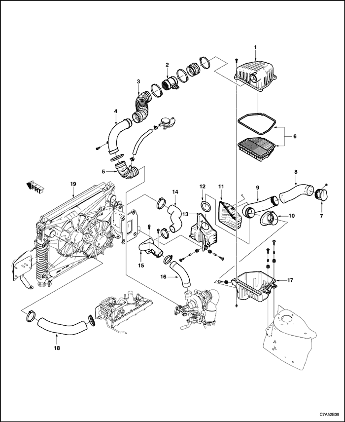


- Air Cleaner Upper Housing
- Mass Air Flow Sensor
- Air Cleaner Outlet Duct Elbow
- Turbocharger Inlet Duct
- Turbocharger Inlet Elbow
- Air Cleaner Element
- Snorkel
- Lower Air Inlet Duct
- Resonator Duct
- Resonator Duct Seal
- Front Resonator
- Resonator Seal
- Rear Resonator
- Charge Air Cooler Inlet Hose
- Charge Air Cooler Inlet Pipe
- Turbocharger Outlet Hose
- Air Cleaner Lower Housing
- Charge Air Cooler Outlet Hose
- Charge Air Cooler
Intake/Exhaust System
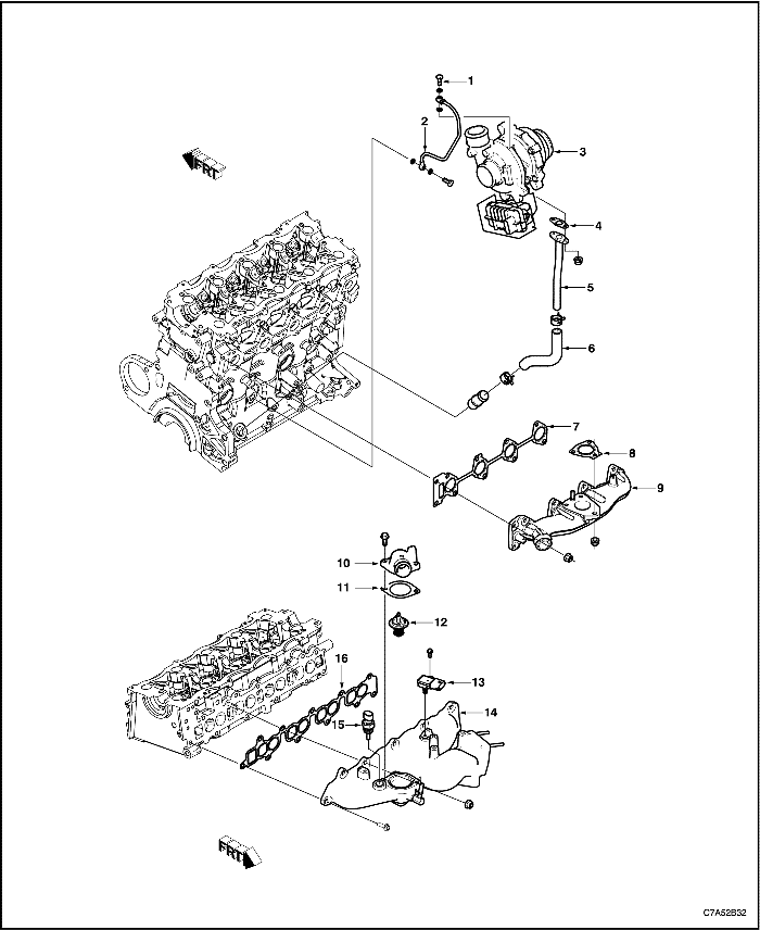
- Wheel Bearing Oil Inlet Pipe Bolt
- Wheel Bearing Oil Inlet Pipe
- Turbocharger
- Wheel Bearing Oil Outlet Pipe Gasket
- Wheel Bearing Oil Outlet Pipe
- Wheel Bearing Oil Outlet Hose
- Exhaust Manifold Gasket
- Turbocharger Gasket
- Exhaust Manifold
- Thermostat Housing
- Thermostat Housing Gasket
- Thermostat
- Boost Pressure Sensor (T-MAP Sensor)
- Intake Manifold
- Coolant Temperature Sensor
- Intake Manifold Gasket
Timing Belt System
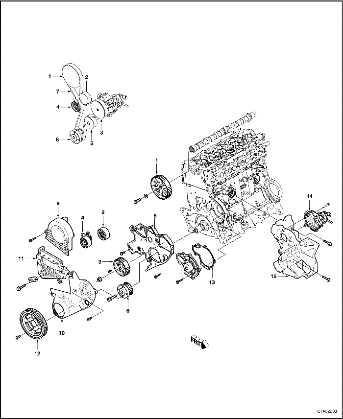
- Camshaft Sprocket
- Timing Belt Idler
- Injection Pump Sprocket
- Timing Belt Tensioner
- Water Pump Pulley
- Crankshaft Sprocket
- Timing Belt
- Timing Belt Rear Cover
- Timing Belt Upper Cover
- Timing Belt Lower Cover
- Engine Mount Bracket
- Crankshaft Pulley
- Water Pump Gasket
- Injection Pump
- A/C compressor & Alternator Bracket
Mount
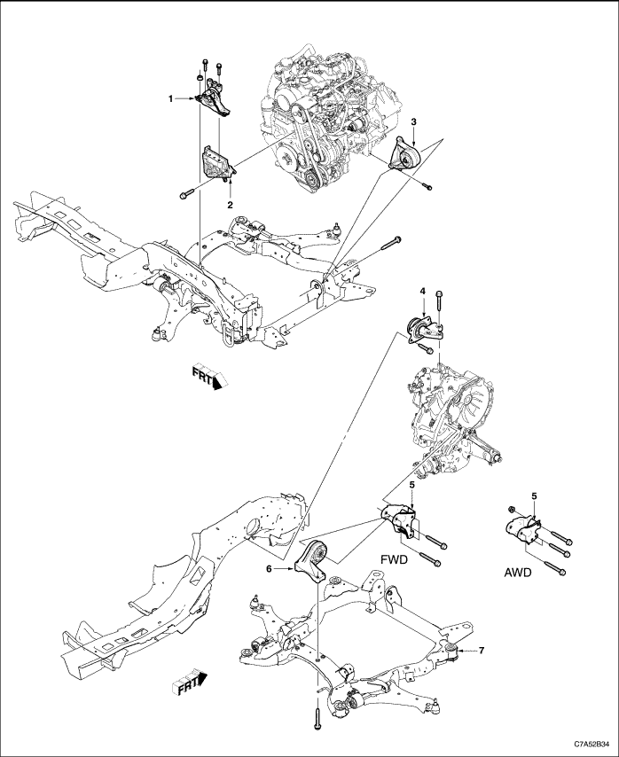
- Engine Mount Damper (RH Side)
- Engine Mount Bracket
- Transaxle Front Mount Damper
- Transaxle Mount Damper (LH Side)
- Transaxle Rear Mount Bracket (AWD/FWD)
- Transaxle Rear Mount Damper
- Cradle
Upper End
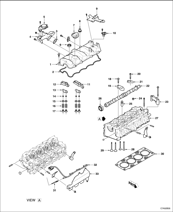
- Camshaft Cover
- Camshaft Cover Gasket
- PCV adapter Gasket
- PCV adapter
- PCV Valve
- Injector Seal
- Oil Cap
- Injector bracket plug
- Engine beauty cover bracket
- Camshaft Position Sensor
- Exhaust Roller Finger-Follower
- Intake Roller Finger-Follower
- Valve Bridge
- Valve Key
- Valve Spring Retainer
- Valve Spring
- Valve Stem Oil Seal
- Camshaft Cap Bolt
- Camshaft Cap
- Injector Bracket Bolt
- Injector Bracket
- Camshaft
- Camshaft Cap
- Plug
- Valve Lash Adjuster
- Camshaft Seal Ring
- Cylinder Head
- Exhaust Valve
- Intake Valve
- Cylinder Head Gasket
- Glow Plug
- Glow Plug Wiring
- Glow Plug Heat Shield
Lower End
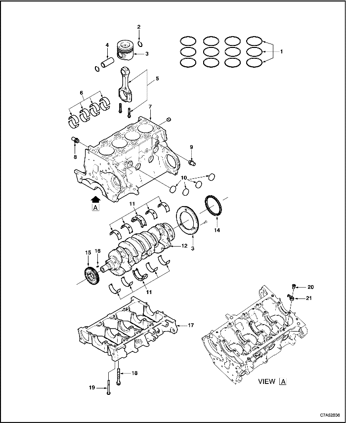
- Piston Ring Set
- Piston Pin Retainer
- Piston
- Piston Pin
- Connecting Rod and Cap
- Connecting Rod Journal Bearing Set
- Engine Block
- Coolant Adapter
- Coolant Adapter
- Plug
- Crankshaft Journal Bearing Set
- Crankshaft
- CKP Sensor Target Wheel
- Crankshaft Rear Seal Ring
- Crankshaft Gear
- Crankshaft Gear Key
- Engine Bed Plate
- Crankshaft Bolt
- Bed Plate Bolt
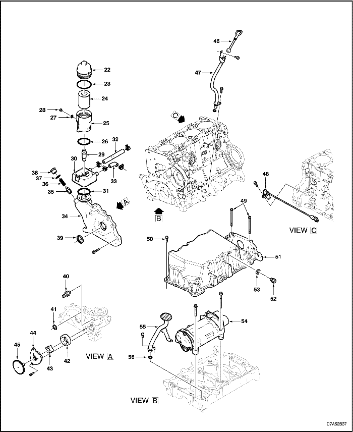
- Oil Nozzle Tube Bolt
- Oil Nozzle Tube
- Oil Filter Cap
- O-Ring
- Oil Filter
- Oil Filter Housing
- O-Ring
- Oil Filter Housing Drain Bolt Washer
- Oil Filter Housing Drain Bolt
- Oil Filter Housing Fitting Bolt
- Engine Oil Cooler
- O-Ring
- Oil Cooler Outlet Hose
- Oil Cooler Inlet Hose
- Oil Pump Assembly
- Oil Pressure Relief Valve
- Oil Pressure Relief Valve Spring
- Oil Pressure Relief Valve Gasket
- Oil Pressure Relief Valve Plug
- Crankshaft Front Seal Ring
- Oil Pressure Switch
- Oil Pump Seal
- Oil Pump Outer Rotor
- Oil Pump Inner Rotor
- Oil Pump Cover
- Oil Pump Drive Gear
- Oil Level Indicator
- Oil Level Indicator Tube
- Crankshaft Position Sensor
- Oil Pan Bolt
- Oil Pan Bolt
- Oil Pan
- Oil Drain Plug
- Oil Drain Plug Washer
- Crankshaft Balancer
- Oil Strainer Pipe
- Oil Strainer Pipe Seal


