MAINTENANCE AND REPAIR
ON-VEHICLE SERVICE
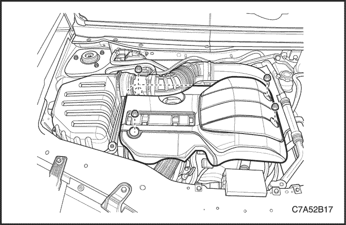


Beauty Cover
Removal/Installation Procedure
- Remove the beauty cover nuts.
- Remove the beauty cover.
Tighten
Tighten the beauty cover nuts to 8 N•m (70.8 lb-in).
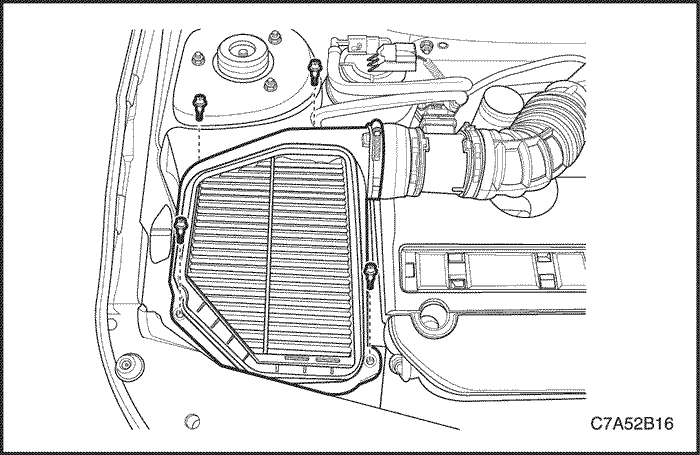
Air Filter Element
Removal/Installation Procedure
- Remove the air cleaner upper housing.
- Replace the air cleaner element.
Notice : Before replacing a new one, check the maintenance interval and the quality of the air cleaner element.
Tighten
Tighten the air cleaner upper housing screws to 2 N•m (17.7 lb-in).
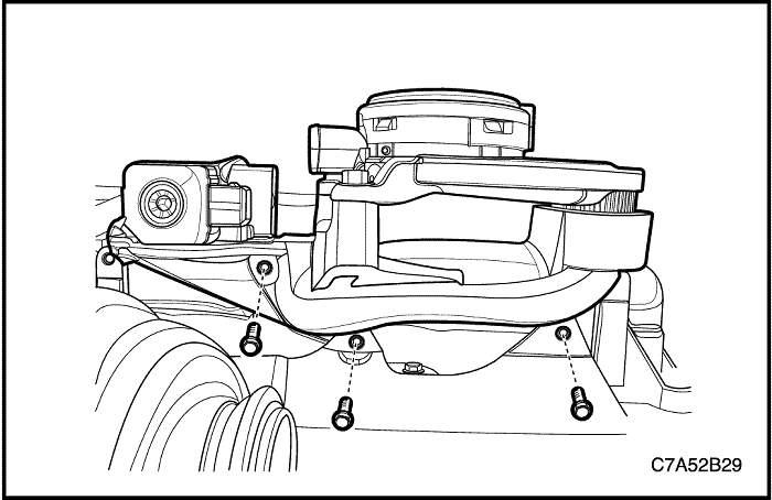
Charging Air System
Removal Procedure
- Disconnect the negative battery cable.
- Remove the beauty cover. Refer to “Beauty Cover”
in this section.
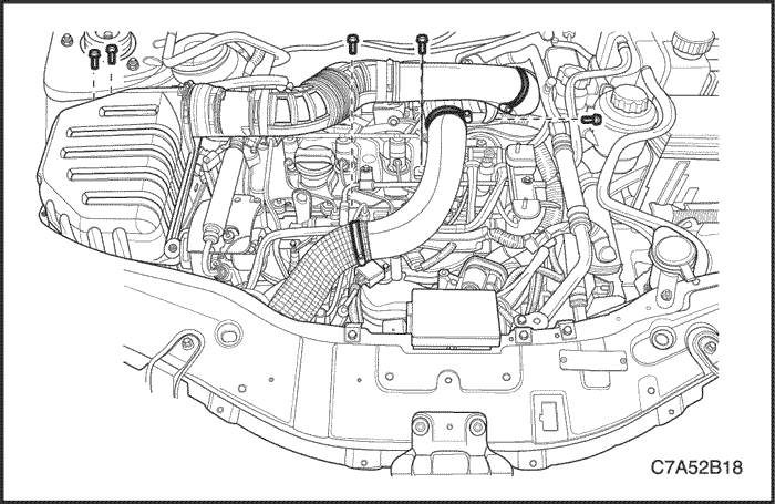
- Disconnect the MAF(Mass Air Flow) sensor connector.
- Remove the air cleaner assembly bolts.
- Remove the turbocharger inlet duct bolt and clamp.
- Remove the air cleaner assembly and turbocharger duct.
- Remove the charge air cooler inlet pipe bolts.
- Remove the charge air cooler inlet pipe.

- Disconnect the PCV hose and clamp from the turbocharger inlet elbow.
- Remove the turbocharger inlet elbow.
- Remove the turbocharger outlet duct.
- Remove the charge air cooler inlet/outlet clamps and ETC(Electric Throttle Control) side clamp.
- Remove the charge air cooler inlet/outlet hoses.
Installation Procedure
- Install the charge air cooler inlet/outlet hoses.
- Install the turbocharger inlet elbow and outlet duct.
- Install the charge air cooler inlet pipe.
Tighten
Tighten the charge air cooler inlet pipe bolts to 8 N•m (70.8 lb-in).
- Install the air cleaner assembly and the turbocharger inlet duct.
Tighten
-
- Tighten the air cleaner assembly bolts to 6 N•m (53 lb-in).
- Tighten the turbocharger inlet duct bolt to 3 N•m (26.6 lb-in).
Charge Air Cooler
Removal Procedure
- Discharge the A/C(Air Conditioning) system, if equipped.
- Remove the radiator grille guide. Refer to Section 9R, Body Front End.
- Remove the radiator grille. Refer to Section 9R, Body Front End.
- Remove the engine under cover. Refer to Section 9N, Frame and Underbody.
- Remove the hood primary latch support. Refer to Section 9R, Body Front End.
- Remove the charge air cooler inlet/outlet hoses. Refer to “Charging Air System”
in this section.
- Remove the A/C condenser from the radiator. Refer to Section 7B, Manual Control Heating, Ventilation and Air conditioning System.

- Remove the radiator upper bracket.
- Remove the charge air cooler bolts.
- Remove the charge air cooler.
Installation Procedure
- Install the charge air cooler to the radiator.
- Install the charge air cooler bolts.
- Install the radiator upper bracket.
Tighten
-
- Tighten the charge air cooler bolts to 8.5 N•m (75.2 lb-in).
- Tighten the radiator upper bracket bolts to 20 N•m (14.8 lb-ft).
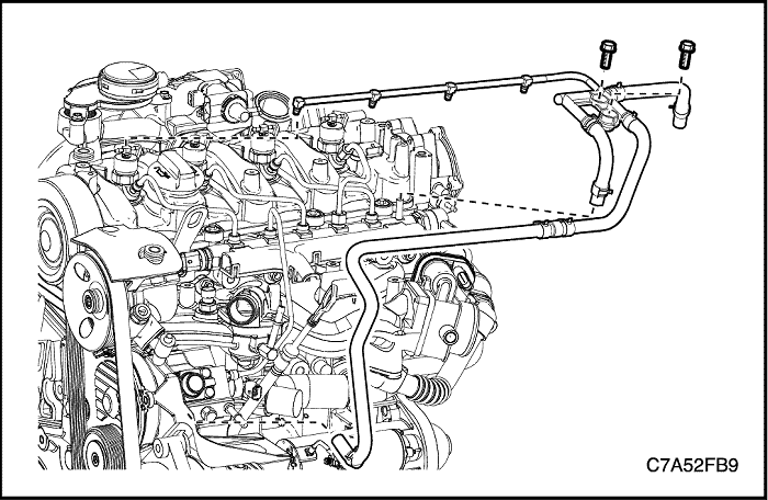
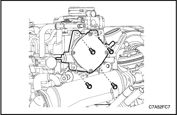
PCV Valve and Adapter
Removal Procedure
- Disconnect the negative battery cable.
- Remove the beauty cover. Refer to “Beauty Cover”
in this section.
- Remove the charge air system hoses and ducts. Refer to “Charging Air System”
in this section.
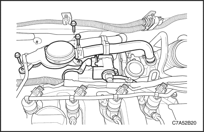
- Disconnect the EGR solenoid connector and inlet/outlet vacuum hoses from EGR solenoid.
- Disconnect the PCV hose from the turbocharger inlet elbow.
- Remove the PCV valve bolts from PCV valve adapter.
- Remove the PCV valve.
- Remove the turbocharger heat shield. Refer to Section 1F1, Engine Controls-2.0 Diesel.
- Remove the PCV valve adapter with the adapter gasket.
Installation Procedure
- Install the PCV valve adapter with a new gasket.
Tighten
Tighten the PCV valve adapter bolts to 11 N•m (97.4 lb-in).
- Install the PCV valve.
Tighten
Tighten the PCV valve bolts to 11 N•m (97.4 lb-in).
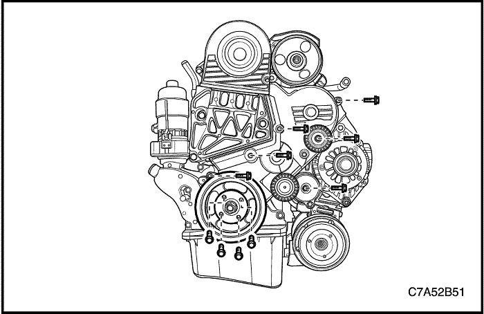
Accessory Belt and Tensioner
Tools Required
EN-48253 Accessory Belt Remover/Installer
EN-48300 Tensioner Remover/Installer
EN-48952 Tensioner Spring Holding Pin
Removal Procedure
- Remove the air cleaner assembly. Refer to “Charging Air System”
in this section.
- Raise and suitably support the vehicle.
- Remove the right front wheel. Refer to Section 2E, Tire and Wheels.
- Remove the engine front shield at the position of right front wheel. Refer to Section 9R, Body Front End.
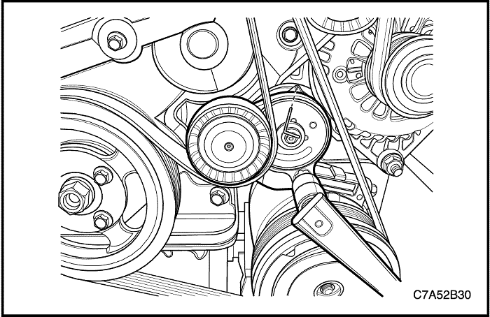
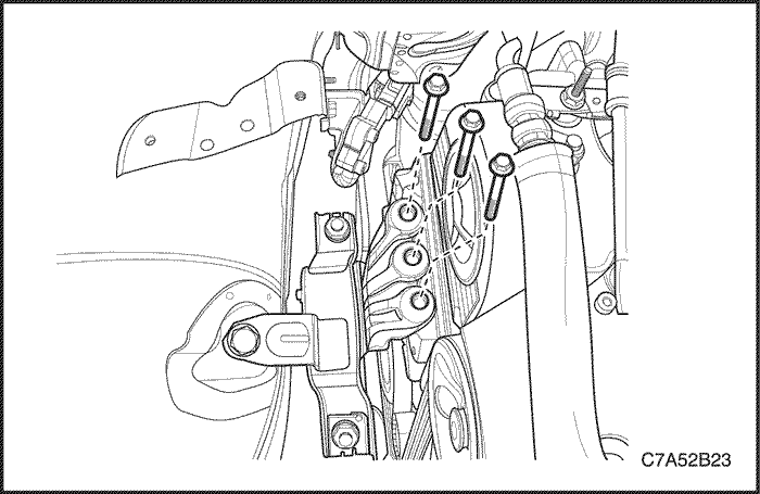
- Install the accessory belt remover/installer EN-48253 onto the tensioner lever guide and rotate the tensioner at clockwise.
- Rotate the tensioner fully and simultaneously insert tensioner spring holding pin EN-48952 to the tensioner pin hole.
- Remove the accessory belt.
- Remove the tensioner using by tensioner remover/installer EN-48300.
Installation Procedure
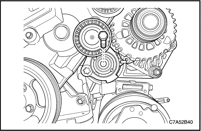
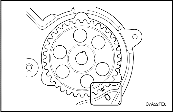
- Install the tensioner bolt manually by hands.
Notice : To not drop the tensioner, screw tightly the tensioner bolt manually by hands. At that moment, the tensioner dowel pin(a) is deviated from the tensioner dowel pin hole(b).
Caution : If extremely rotate the tensioner bolt using by tools, tensioner dowel pin and bracket may wear-out.

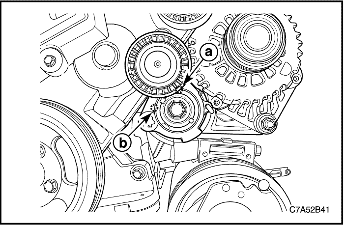
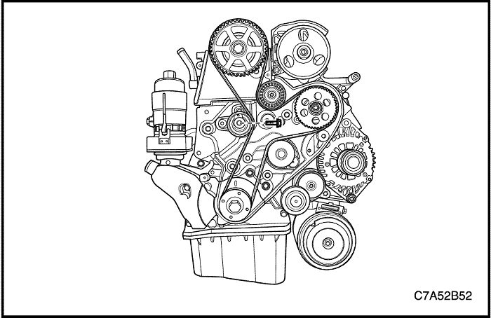
- Install the accessory belt.

- Install the accessory belt remover/installer EN-48253 to the tension lever guide and rotate the tensioner at count-clockwise.
Notice : The tensioner dowel pin(a) is inserted into the tensioner dowel pin hole(b).
- Install the tensioner using by tensioner remover/installer EN-48300.
Tighten
Tighten the tensioner retaining bolt to 48 N•m (35.4 lb-ft).
- Remove tensioner spring holding pin EN-48952 using by the accessory belt remover/installer EN-48253.
Intake Manifold
Removal Procedure
- Disconnect the negative battery cable.
- Remove the beauty cover. Refer to “Beauty Cover”
in this section.
- Remove the charge air system hoses and ducts. Refer to “Charging Air System”
in this section.
- Disconnect the radiator lower hose and drain coolant. Refer to Section 1D1, Engine Cooling-2.0 Diesel.
- Remove the accessory belt. Refer to “Accessory Belt and Tensioner”
in this section.

- Remove the fuel pipe-to-injection pump from the fuel injection pump.
- Remove the power steering pump fastener and pull it left side.
- Remove the coolant hose from intake manifold.
- Remove the radiator upper hose.
- Remove the injection pump return hose.
- Remove the oil level indicator tube.
- Remove the fuel pipe-to-common rail between common rail and fuel injection pump. Refer to Section 1F1, Engine Controls-2.0 Diesel.
- Remove the wiring splice pack tightening bolt from intake manifold.
- Remove the glow plug fuse box retaining bolts.
- Remove the engine wiring.
- Disconnect the common rail pressure sensor connector.
- Disconnect the CTS connector.
- Disconnect the injection pump connector.
- Disconnect the generator connector.
- Disconnect the A/C compressor connector.
- Disconnect the starter solenoid wire connector.
- Disconnect the cooling fan connectors.
- Disconnect the T-MAP sensor connector.
- Disconnect the CMP sensor connector.
- Disconnect the ETC body connector.
- Disconnect the common rail regulator connector.
- Remove the engine wiring harness guide.
- Remove the coolant by-pass hose.
- Remove the EGR cooler outlet pipe.
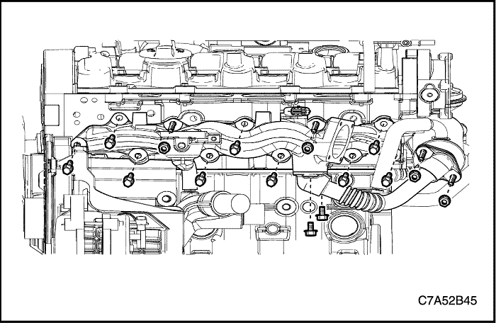
- Remove the intake manifold with the gasket.
Installation Procedure
- Install the intake manifold with a new gasket.
- Install the EGR cooler outlet pipe.
Tighten
-
- Tighten the intake manifold bolts and nuts 23 N•m (17 lb-ft).
- Tighten the EGR cooler outlet pipe bolts and nuts 20 N•m (14.8 lb-ft).
- Install the engine wiring.
- Install the glow plug fuse box retaining bolts.
- Install the engine wiring splice pack tightening bolt to intake manifold.
- Install the fuel pipe-to-common rail between common rail and fuel injection pump. Refer to Section 1F1, Engine Controls-2.0 Diesel.
- Install the oil level indicator tube.
- Install the power steering pump.
- Install the fuel pipe-to-injection pump to the fuel injection pump.
Tighten
-
- Tighten the glow plug fuse box bolts to 10 N•m (88.5 lb-in).
- Tighten the engine wiring splice pack tightening bolt to 15 N•m (11.1 lb-ft).
- Tighten the fuel pipe-to-common rail to 20 N•m (14.8 lb-ft).
- Tighten the fuel pipe-to-common rail retaining bolt to 10 N•m (88.5 lb-in).
- Tighten the oil level indicator tube bolts to 11 N•m (97.4 lb-in).
- Tighten the power steering pump bolts to 25 N•m (18.4 lb-ft).
- Tighten the fuel pipe-to-injection pump retaining bolt(to intake manifold) to 9 N•m (79.7 lb-in).
- Tighten the fuel pipe-to-injection pump retaining bolt to 25 N•m (18.4 lb-ft).
Exhaust Manifold
Removal Procedure
Caution : Do not remove when the exhaust manifold parts are hot.
- Disconnect the negative battery cable.
- Remove the beauty cover. Refer to “Beauty Cover”
in this section.
- Remove the charge air system hoses and ducts. Refer to “Charging Air System”
in this section.
- Remove the PCV valve and adapter. Refer to “PCV Valve and Adapter”
in this section.
- Remove the exhaust heat shield.

- Remove the pre-catalyst. Refer to Section 1G1, Engine Exhaust - 2.0 Diesel.
- Remove the turbocharger from the exhaust manifold. Refer to Section 1F1, Engine Controls - 2.0 Diesel.
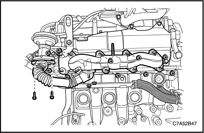
- Remove the EGR cooler inlet pipe from the EGR valve with the gasket.
- Remove the exhaust manifold with the EGR cooler inlet pipe.
- Remove the EGR cooler inlet pipe from the exhaust manifold.
Installation Procedure
- Install the EGR cooler inlet pipe to the exhaust manifold.
- Install the exhaust manifold to the cylinder head with a new gasket.
- Install the EGR cooler inlet pipe to the EGR valve with a new gasket.
Tighten
-
- Tighten the EGR cooler inlet pipe nuts(to exhaust manifold) to 33 N•m (24.3 lb-ft).
- Tighten the exhaust manifold nuts to 33 N•m (24.3 lb-ft).
- Tighten the EGR cooler inlet pipe bolts(to EGR valve) to 20 N•m (14.8 lb-ft).
- Install the exhaust manifold heat shield.
Tighten
Tighten the exhaust manifold heat shield nuts and bolt to 20 N•m (14.8 lb-ft).
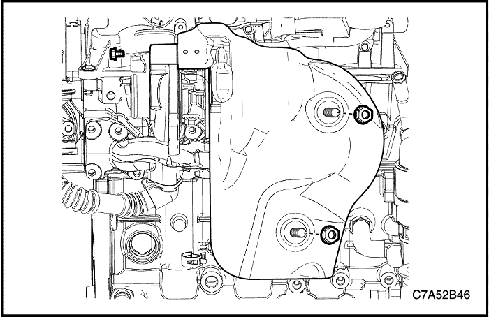
Cylinder Head Cover
Removal Procedure
- Disconnect the negative battery cable.
- Remove the beauty cover. Refer to “Beauty Cover”
in this section.
- Remove the charge air system hoses and ducts. Refer to “Charging Air System”
in this section.
- Remove the PCV valve and adapter. Refer to “PCV Valve and Adapter”
in this section.
- Remove the fuel pipe-to-injector between the common rail and the injector. Refer to Section 1F1, Engine Controls - 2.0 Diesel.
- Remove the fuel return line assembly. Refer to Section 1F1, Engine Controls - 2.0 Diesel.
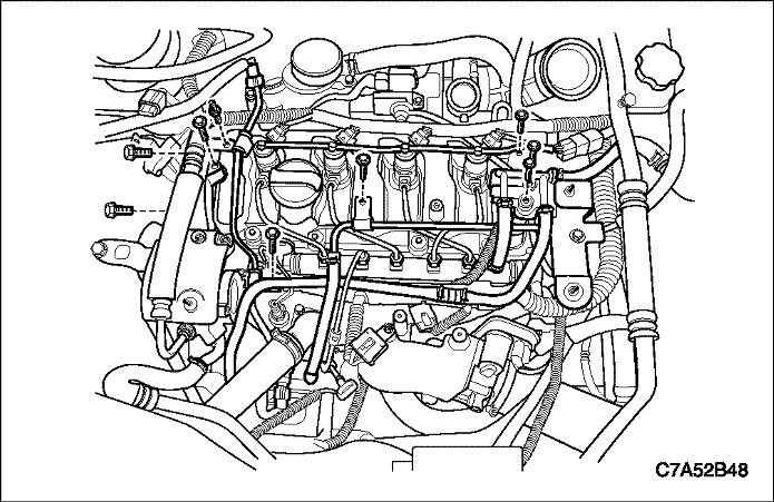
- Remove the beauty cover bracket with coolant return pipe from the surge tank.
- Remove the timing belt upper cover.
- Disconnect the CMP sensor connector.
- Remove the injectors. Refer to Section 1F1, Engine Controls - 2.0 Diesel.
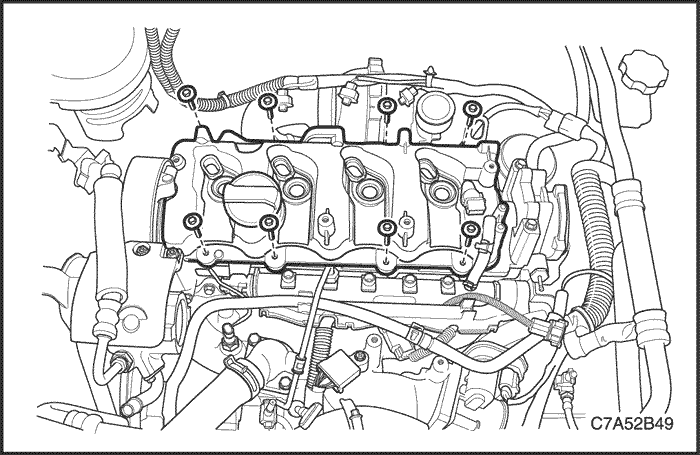
- Remove the cylinder head cover with the gasket.
Cleaning Procedure
- Clean the cylinder head cover sealing surface.
- Clean the cylinder head sealing surface.
- Clean the cylinder head cover bolts.
- Clean the cylinder head cover bolt holes.
Installation Procedure
- Coat the sealant(LOCTITE 5900) on the camshaft front/rear cap surface.
- Install the cylinder head cover with a new gasket on the cylinder head.
Tighten
Tighten the cylinder head cover bolts to 12 N•m (8.9 lb-ft).
- Install the timing belt upper cover.
- Install the beauty cover bracket with coolant return pipe to the surge tank.
- Install the fuel return line assembly.
- Install the fuel pipe-to-injector between the common rail and the injector. Refer to Section 1F1, Engine Controls - 2.0 Diesel.
Tighten
-
- Tighten the timing belt upper cover bolts to 11 N•m (97.4 lb-in).
- Tighten the coolant return pipe retaining bolt 9 N•m (79.7 lb-in).
- Tighten the junction block bolts to 11 N•m (97.4 lb-in).
- Tighten the beauty cover bracket bolt to 11 N•m (97.4 lb-in).
Timing Belt System
Tools Required
DW110–060 Engine Assembly Support Fixture
EN-48245 Timing Belt Adjuster - Camshaft Holder
EN-48246 Timing Belt Adjuster - Crankshaft Holder
Removal Procedure
- Disconnect the negative battery cable.
- Remove the beauty cover. Refer to “Beauty Cover”
in this section.
- Remove the charge air system hoses and ducts. Refer to “Charging Air System”
in this section.
- Remove the accessory belt. Refer to “Accessory Belt and Tensioner”
in this section.
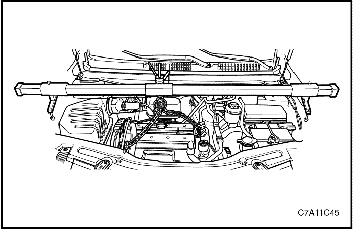
Caution : Only lift the engine far enough to take the weight off the engine mount assembly, or damage to the mount and lifting equipment failure may occur.
- Support the engine assembly using the engine assembly support fixture DW110–060.
- Remove the engine mount damping block. Refer to “Engine Mount Assembly (RH Side)”
in this section.
- Remove the timing belt upper cover.
- Remove the accessory belt idler.
- Remove the tensioner. Refer to “Accessory Belt and Tensioner”
in this section.
- Remove the crankshaft pulley.
- Remove the timing belt lower cover.
- Remove the engine mount bracket.
- Remove the timing belt tensioner.
- Remove the timing belt.
- Remove the camshaft sprocket.
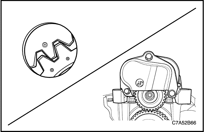
Timing Belt Adjustment
- Remove the vacuum pump. Refer to Section 1F1, Engine Controls - 2.0 Diesel.

- Rotate the camshaft and align the hole on the top point.
- Rotate the crankshaft and align the mark on the crankshaft sprocket.

- Remove the crankshaft holder hole cap bolt(a).
- Insert the crankshaft holder EN-48246 into the crankshaft holder hole.(b)
Notice : Rotate the crankshaft sprocket a little and simultaneously insert the crankshaft holder.
- Install the camshaft holder EN-48245 onto the camshaft rear side.(c)
- Align the sprocket mark on the timing belt rear cover mark.
- Install the camshaft sprocket with the tightening bolt manually.
- Install the timing belt.
- Install the timing belt tensioner with the tightening bolt manually.

- Turn the hex-key(a) tab in a count-clockwise direction to tension the belt. Turn until the point aligns with the notch(b).
- Aligning with notch, install the timing belt tensioner bolt.
- Install the camshaft sprocket bolt.
Tighten
-
- Tighten the timing belt tensioner bolt to 25 N•m (18.4 lb-in).
- Tighten the camshaft sprocket bolt to 133 N•m (98.1 lb-in).
- Remove the camshaft holder EN-48245 and crankshaft holder EN-48246.
- Turn the crankshaft in a clockwise direction more 2 cycles and check the mark on the crankshaft sprocket.
- After alignment of the timing belt, install the crankshaft holder hole cap bolt.
Tighten
Tighten the crankshaft holder hole cap bolt to 30 N•m (22.1 lb-ft).
Notice : If not aligns No.1 cylinder TDC point, do work again above procedure No.4~ No.10 until aligns that.
Caution : Because the setting of these service special tools is aligns No.1 cylinder TDC point, if not exactly aligns, it has influence on engine performance and emission.
Installation Procedure
- Install the engine mount bracket.
- Install the timing belt lower cover.
- Install the crankshaft pulley.
- Install the accessory belt idler.
- Install the timing belt upper cover.
Tighten
-
- Tighten the engine mount bracket bolts to 45 N•m (33.1 lb-ft).
- Tighten the timing belt lower cover bolts to 11 N•m (97.4 lb-in).
- Tighten the crankshaft pulley bolts to 34 N•m (25.1 lb-ft).
- Tighten the accessory belt idler bolt to 52 N•m (38.4 lb-ft).
- Tighten the timing belt upper cover bolts to 11 N•m (97.4 lb-in).
Cylinder Head and Gasket
Removal Procedure
- Disconnect the negative battery cable.
- Remove the beauty cover. Refer to “Beauty Cover”
in this section.
- Remove the charge air system hoses and ducts. Refer to “Charging Air System”
in this section.
- Remove the accessory belt. Refer to “Accessory Belt and Tensioner”
in this section.
- Remove the cylinder head cover. Refer to “Cylinder Head Cover”
in this section.
- Remove the timing belt. Refer to “Timing Belt System”
in this section.

- Remove the fuel pipe-to-common rail between common rail and fuel injection pump. Refer to Section 1F1, Engine Controls - 2.0 Diesel.
- Remove the power steering pump fastener and pull it left side.
- Remove the engine wiring splice pack tightening bolt.
- Remove the oil level indicator tube.
- Remove the radiator upper hose from the thermostat housing.
- Remove the engine wiring connectors.
- Remove the turbocharger wheel bearing oil inlet pipe.
- Remove the turbocharger wheel bearing oil outlet hose.
- Remove the pre-catalyst tightening clamp from the turbocharger.

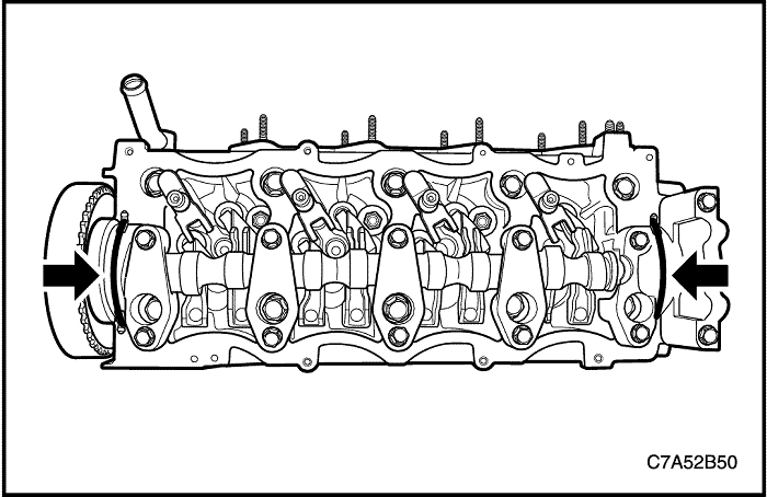
- Remove the cylinder head bolts.
- Remove the cylinder head assembly with the gasket.
- Remove the intake manifold and exhaust manifold from cylinder head assembly. Refer to “Intake Manifold” and “Exhaust Manifold”
in this section.
Cleaning Procedure
- Clean the cylinder head surface.
- Clean the engine block surface.
- Clean the cylinder head bolts.
- Clean the engine block bolt holes.
Choose the Gasket
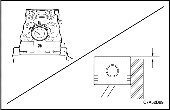
- Align the TDC of the piston.
- Clean the cylinder block sealing surface and piston.
- Measure the piston projection thickness using by dial gauge.
- Repeat the measuring process on the other cylinders and average the measured piston projection values.
- Choose the cylinder head gasket through below the specifications.
|
Piston Projection (mm)
|
Gasket Thickness (mm)
|
|
0.194 ~ 0.337
|
1.1
|
|
0.337 ~ 0.440
|
1.2
|
|
0.440 ~ 0.542
|
1.3
|
Installation Procedure
- Install the cylinder head assembly with a new gasket.
- Install the cylinder head tightening bolts.
Tighten
Tighten the cylinder head bolts to 65 N•m(47.9 lb-ft). Using the angular torque gauge KM-470-B, tightening the cylinder head bolts another 120 degrees plus 120 degrees.
- Install the pre-catalyst tightening clamp to the turbocharger.
- Install the turbocharger wheel bearing oil inlet pipe.
Tighten
Tighten the turbocharger wheel bearing oil inlet pipe bolts to 23 N•m(17 lb-ft).
- Install the engine wiring splice pack tightening bolt.
- Install the power steering pump fastener.
- Install the fuel pipe-to-common rail between common rail and fuel injection pump.
- Install the oil level indicator tube.
Tighten
-
- Tighten the engine wiring splice pack tightening bolt to 15 N•m (11.1 lb-ft).
- Tighten the power steering pump bolts to 25 N•m (18.4 lb-ft).
- Tighten the fuel pipe-to-common rail to 20 N•m (14.8 lb-ft).
- Tighten the fuel pipe-to-common rail retaining bolt to 10 N•m (88.5 lb-in).
- Tighten the oil level indicator tube bolts to 11 N•m (97.4 lb-in).
Engine Oil Filter and Cooler
Removal Procedure
- Disconnect the negative battery cable.
- Remove the beauty cover. Refer to “Beauty Cover”
in this section.
- Remove the charge air system hoses and ducts. Refer to “Charging Air System”
in this section.
- Remove the fuel filter assembly. Refer to Section 1F1, Engine Controls - 2.0 Diesel.
- Drain the engine oil.
- Remove the oil filter housing drain bolt with washer and drain the engine oil in the oil filter housing.
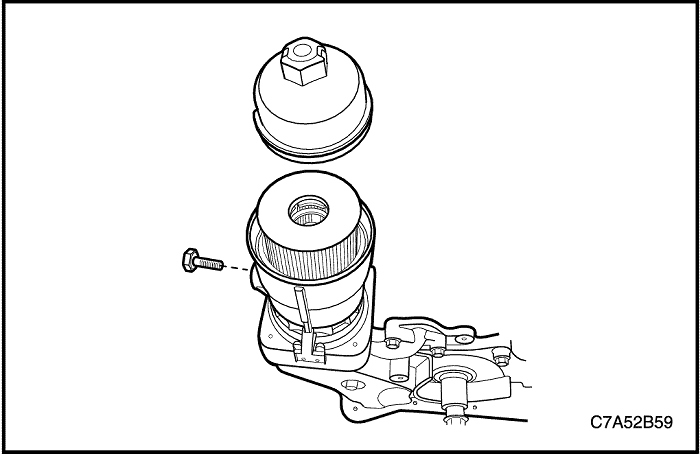
- Remove the oil filter cap with the O-ring.
- Remove the oil filter.
Notice : Check the engine oil maintenance interval and replace the engine oil filter according to the interval. Also, you can check the engine oil remaining life in the scan tool.
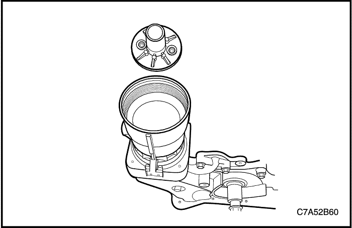
- Remove the oil filter housing adapter plate.
- Remove the oil filter housing with the O-ring.
- Drain the engine coolant. Refer to Section 1D1, Engine Cooling - 2.0 Diesel.
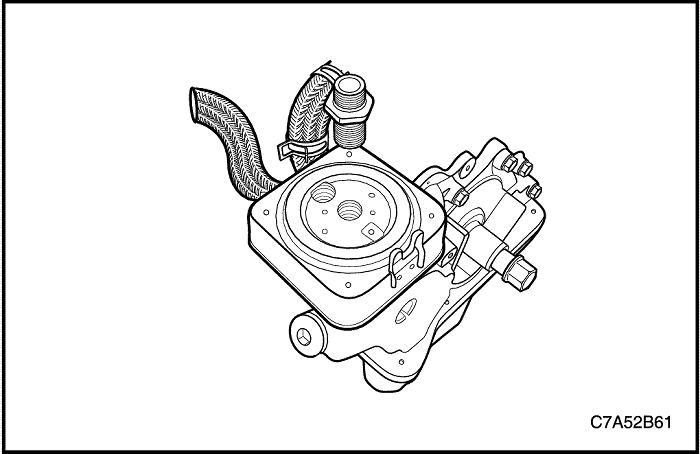
- Remove the oil filter housing fitting bolt.
- Disconnect the engine oil cooler inlet/outlet hoses.
- Remove the engine oil cooler with the O-ring.
Installation Procedure
- Install the engine oil cooler with a new O-ring.
- Connect the engine oil cooler inlet/outlet hoses.
Tighten
Tighten the engine oil filter housing fitting bolt to 50 N•m(36.9 lb-ft).
- Install the engine oil filter housing with a new O-ring.
- Install the oil filter housing adapter plate.
Tighten
Tighten the oil filter housing adapter plate to 40 N•m(29.5 lb-ft).
- Install the engine oil filter and cap with a new O-ring.
Tighten
Tighten the engine oil filter cap to 25 N•m (18.4 lb-ft).
Important : If you change the new engine oil, reset the engine oil life by scan tool.
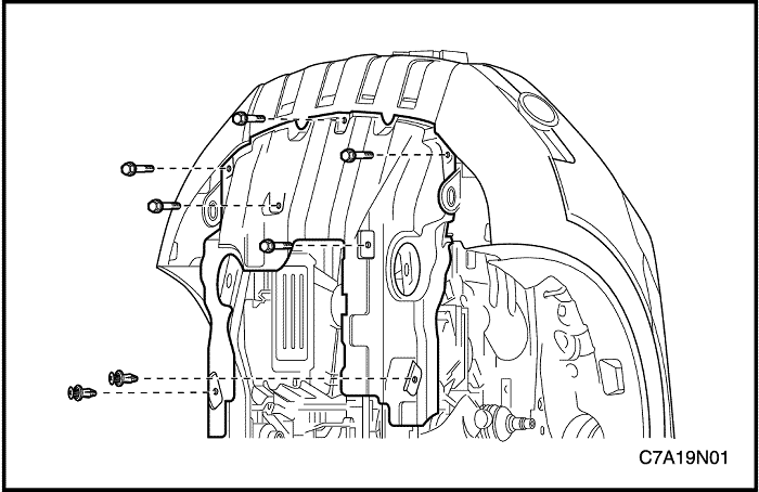
Oil Pan
Removal Procedure
- Remove the engine undercover. Refer to Section 9N, Frame and Underbody.
- Drain the engine oil.
- Remove the charge air system hoses and ducts. Refer to Section 3B, Front Drive Axle.

- Remove the oil pan flange-to-transaxle bolts.
- Remove the A/C compressor lower bolts.
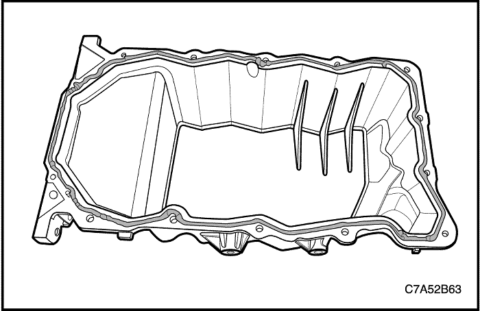
- Remove the oil pan.
Cleaning Procedure
- Clean the oil pan sealing surface.
- Clean the engine bed plate sealing surface.
- Clean the oil pan bolts.
- Clean the engine bed plate bolt holes.
Installation Procedure
Important : If you change the new engine oil, reset the engine oil life by scan tool.
- Coat the sealant(LOCTITE 5900) on the oil pan sealing surface.
- Install the oil pan.
- Install the A/C compressor lower bolts.
- Install the oil pan flange-to-transaxle bolts.
Tighten
-
- Tighten the oil pan tightening bolts to 11 N•m (97.4 lb-in).
- Tighten the A/C compressor lower bolts to 23 N•m (17 lb-ft).
- Tighten the oil pan flange-to-transaxle bolts to 50 N•m (36.9 lb-ft).
Oil Strainer
Removal/Installation Procedure
Important : If you change the new engine oil, reset the engine oil life by scan tool.
- Remove the engine undercover. Refer to Section 9N, Frame and Underbody.
- Drain the engine oil.
- Remove the oil pan. Refer to “Oil Pan”
in this section.
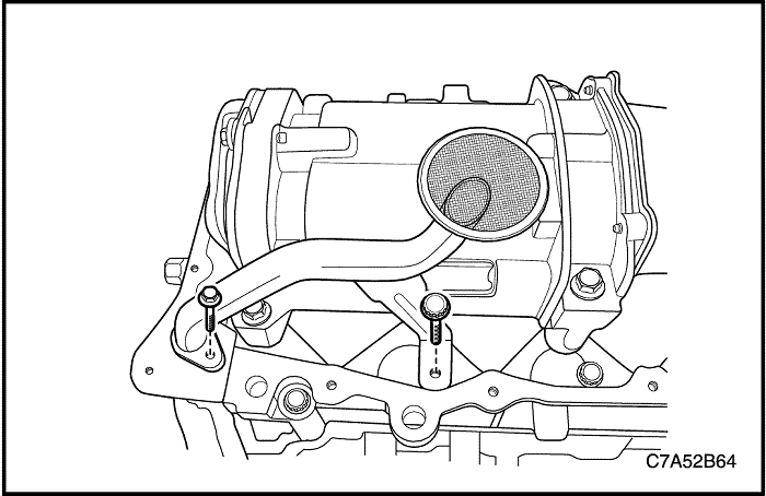
- Remove the oil strainer with washer.
Tighten
-
- Tighten the oil strainer bolt to 11 N•m (97.4 lb-in).
- Tighten the oil strainer bracket bolt(bed plate outer bolt) to 35 N•m (25.8 lb-ft).
Crankshaft Balancer
Removal Procedure
- Remove the engine undercover. Refer to Section 9N, Frame and Underbody.
- Drain the engine oil.
- Remove the oil pan. Refer to “Oil Pan”
in this section.
- Remove the oil strainer. Refer to “Oil Strainer”
in this section.

- Remove the crankshaft balancer.
Installation Procedure
Important : If you change the new engine oil, reset the engine oil life by scan tool.
- Install the crankshaft balancer.
Tighten
Tighten the crankshaft balancer bolts to 55 N•m (46 lb-ft).
- Turn the crankshaft and align the crankshaft balancer 3-point on the gears.
Caution : Do not disassemble the crankshaft balancer. Otherwise, the engine and body may be able to vibrate.
Oil Pump
Tools Required
EN-48250 Crankshaft Front Oil Seal Installer
Removal Procedure
- Disconnect the negative battery cable.
- Remove the beauty cover. Refer to “Beauty Cover”
in this section.
- Remove the charge air system hoses and ducts. Refer to “Charging Air System”
in this section.
- Remove the accessory belt. Refer to “Accessory Belt and Tensioner”
in this section.
- Remove the engine mount damping block. Refer to “Engine Mount Assembly (RH Side)”
in this section.
- Drain the engine oil.
- Remove the timing belt. Refer to “Timing Belt System”
in this section.
- Remove the timing belt idler.
- Remove the injection pump sprocket.
- Remove the timing belt rear cover.
- Remove the crankshaft sprocket.
- Disconnect the engine oil pressure switch connector.
- Disconnect the engine oil cooler inlet/outlet hoses. Refer to “Engine Oil Filter and Cooler”
in this section.
- Remove the engine oil pump assembly.
Cleaning Procedure
- Clean the oil pump sealing surface.
- Clean the engine block sealing surface.
- Clean the oil pump tightening bolts.
- Clean the oil pump bolt holes.

Installation Procedure
Important : If you change the new engine oil, reset the engine oil life by scan tool.
- Coat the sealant(LOCTITE 5900) on the oil pump sealing surface.
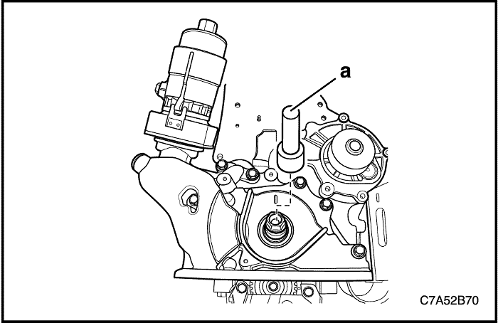
- Install the oil pump assembly with a new oil pump seal.
- Install the crankshaft front seal ring using by Crankshaft Front Oil Seal Installer EN-48250.(a)
Notice : If the crankshaft front oil seal is damaged, replace it with new oil seal. When installing the crankshaft front oil seal to the oil pump, make the oil seal groove faced toward the oil pump case contact.
Tighten
Tighten the oil pump tightening bolts to 24 N•m (17.7 lb-ft).
- Install the timing belt rear cover.
- Install the injection pump sprocket.
- Install the timing belt idler.
Tighten
-
- Tighten the timing belt rear cover bolts to 11 N•m (97.4 lb-in).
- Tighten the injection pump sprocket nut to 70 N•m (51.6 lb-in).
- Tighten the timing belt idler retaining bolt to 52 N•m (38.4 lb-in).
- Install the crankshaft sprocket.
Tighten
Tighten the crankshaft sprocket nut to 235 N•m (173.3 lb-ft).
Engine Bed Plate
Removal Procedure
- Disconnect the negative battery cable.
- Remove the beauty cover. Refer to “Beauty Cover”
in this section.
- Remove the charge air system hoses and ducts. Refer to “Charging Air System”
in this section.
- Remove the accessory belt. Refer to “Accessory Belt and Tensioner”
in this section.
- Remove the engine mount damping block. Refer to “Engine Mount Assembly (RH Side)”
in this section.
- Drain the engine oil.
- Remove the timing belt. Refer to “Timing Belt System”
in this section.
- Remove the oil pump. Refer to “Oil Pump”
in this section.

- Remove the bed plate-to-transaxle bolt.
- Remove the engine block ground bolt.
- Remove the engine bed plate.
Cleaning Procedure
- Clean the bed plate sealing surface.
- Clean the engine block sealing surface.
- Clean the bed plate tightening bolts.
- Clean the bed plate bolt holes.
Installation Procedure
Important : If you change the new engine oil, reset the engine oil life by scan tool.
- Coat the sealant(Hylomar 3000) on the bed plate sealing surface.
- Install the bed plate.
- Install the engine block ground bolt.
- Install the bed plate-to-transaxle bolt.
Tighten
-
- Tighten the bed plate inner bolts to 25 N•m(18.4 lb-ft). Using the angular torque gauge KM-470-B, tighten bed plate inner bolts another 45 degrees plus 90 degrees.
- Tighten the bed plate outer bolts to 35 N•m (25.8 lb-ft).
- Tighten the engine block ground bolt to 25 N•m (18.4 lb-ft).
- Tighten the transaxle tightening bolt(bed plate-to-transaxle bolt) to 75 N•m (55.3 lb-ft).
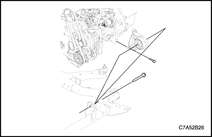
Engine Mount Assembly (RH Side)
Tools Required
DW110–060 Engine Assembly Support Fixture
Removal Procedure
Caution : Only lift the engine far enough to take the weight off the engine mount assembly, or damage to the mount and lifting equipment failure may occur.
- Support the engine assembly using the engine assembly support fixture DW110–060.
- Remove the engine mount adapter retaining bolts from the engine mount support bracket.
- Remove the engine mount frame side bracket retaining bolt and nuts.
- Remove the engine mount assembly.
Installation Procedure
- Install the engine mount assembly.
Tighten
-
- Tighten the engine mount frame side bracket retaining bolt to 100 N•m (73.8 lb–ft) and nuts to 90 N•m (66.4 lb–ft).
- Tighten the engine mount bracket retaining bolts to 50 N•m (37 lb–ft).
- Remove the engine assembly support fixture DW110–060.
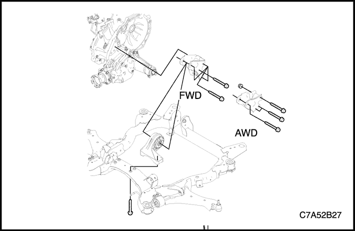
Transaxle Front Mount Assembly
Tools Required
DW110–060 Engine Assembly Support Fixture
Removal Procedure
Caution : Only lift the engine far enough to take the weight off the transaxle front mount assembly, or damage to the mount and lifting equipment failure may occur.
- Support the engine assembly using the engine assembly support fixture DW110–060.
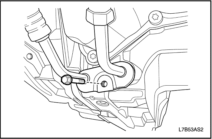
- Remove the transaxle front mount–to–transaxle through bolt.
- Remove the transaxle front mount retaining bolts from the transaxle.
- Remove the transaxle front mount assembly.
Installation Procedure
- Install the transaxle front mount assembly.
Tighten
Tighten the transaxle front mount retaining bolts to 50 N•m (36.9 lb–ft).
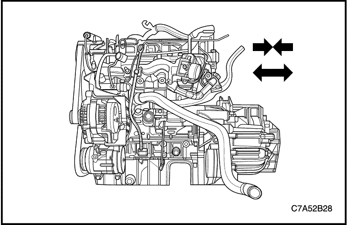
Caution : Before tightening the transaxle front mount through bolt swing the engine assembly backwards and forwards or from the side to side for the proper alignment.
- Install the transaxle front mount through bolt.
Tighten
Tighten the transaxle front mount–to–transaxle through bolt to 90 N•m (66 lb–ft).
Transaxle Rear Mount Assembly
Tools Required
DW110–060 Engine Assembly Support Fixture
Removal Procedure
Caution : Only lift the engine far enough to take the weight off the transaxle rear mount assembly, or damage to the mount and lifting equipment failure may occur.
- Support the engine assembly using the engine assembly support fixture DW110–060.
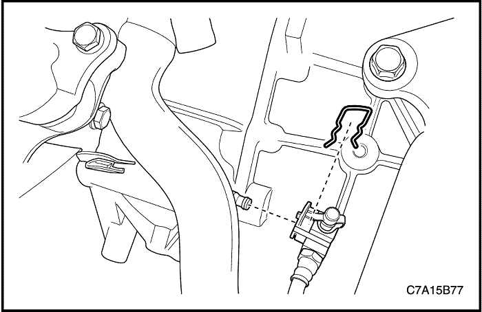
- Remove the transaxle rear mount–to–bracket through bolt.
- Remove the transaxle rear mount bracket retaining bolts from the transaxle.
- Remove the transaxle rear mount bracket.
- Remove the transaxle rear mount retaining bolts from the cradle.
- Remove the transaxle rear mount.
Installation Procedure
- Install the transaxle rear mount to the cradle.
Tighten
Tighten the transaxle rear mount retaining bolts to 90 N•m (66 lb–ft).
- Install the transaxle rear mount bracket to the transaxle.
Tighten
Tighten the transaxle rear mount bracket retaining bolts to 90 N•m (66 lb–ft).
Caution : Before tightening the transaxle rear mount through bolt, swing the engine assembly backwards and forwards or from the side to side for the proper alignment.
- Install the transaxle rear mount through bolt.
Tighten
Tighten the transaxle rear mount–to–bracket through bolt to 90 N•m (66 lb–ft).
Engine Assembly
Tools Required
EN–48243 Engine Assembly Remove/Install Pallet
EN–48244 Engine Assembly Remove/Install Pallet Supporter
Removal Procedure
- Discharge the air conditioning(A/C) system, if equipped.
- Drain the power steering oil, if equipped.
- Disconnect the negative battery cable.
- Remove the beauty cover. Refer to “Beauty Cover”
in this section.
- Remove the charge air system hoses and ducts. Refer to “Charging Air System”
in this section.
- Drain the engine coolant. Refer to Section 1D1, Engine Cooling - 2.0 Diesel.

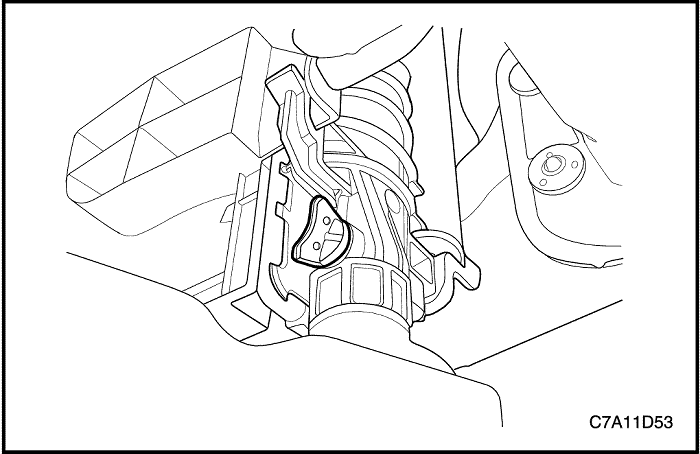
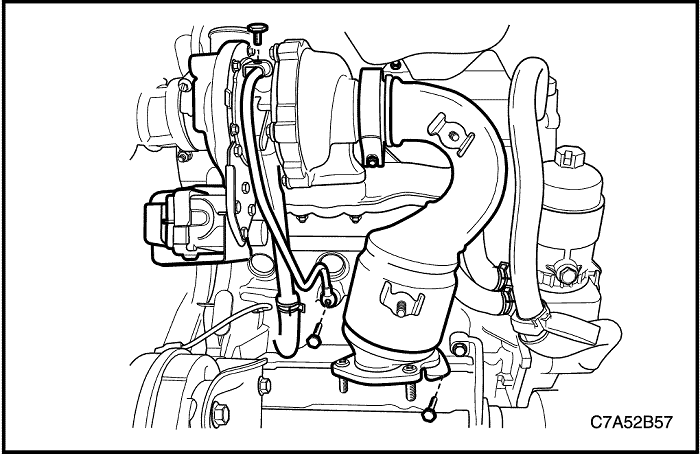
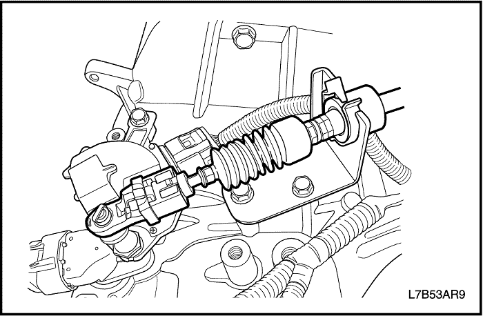
- Disconnect the fuel feeding pipe connector.(a)
- Disconnect the coolant hose from the surge tank.(b, c)
- Disconnect the fuel return hose from the junction block.(d)
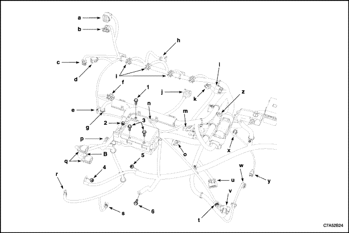
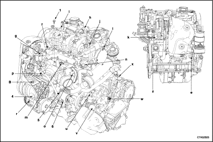
- Disconnect the engine wiring harness.
-
- a) Disconnect the fuel heater wiring connector.
- b) Disconnect the mass air flow sensor(MAF) connector.
- c) Disconnect the exhaust temperature sensor wiring connector.
- d) Disconnect the DPF pressure sensor connector.
- e) Disconnect the engine oil pressure switch connector.
- f) Disconnect the common rail pressure sensor connector.
- g) Disconnect the coolant temperature sensor connector.
- h) Disconnect the EGR vacuum solenoid connector.
- i) Disconnect the fuel injector connector.
- j) Disconnect the camshaft position sensor(CMP) connector.
- k) Disconnect the turbocharger actuator connector.
- l) Disconnect the glow plug wire connector.
- m) Disconnect the booster pressure(T-MAP) sensor connector.
- n) Disconnect the common rail regulator connector.
- o) Disconnect the ETC body connector.
- p) Disconnect the fuel injection pump connector.
- q) Disconnect the cooling fan connectors.
- r) Disconnect the A/C compressor connector.
- s) Disconnect the starter solenoid wiring connector.
- t) Disconnect the A/C pressure sensor connector.
- u) Disconnect the transaxle range(TR) switch connector, if auto-transaxle.
- v) Disconnect the transaxle wiring electrical connector, if auto-transaxle.
- w) Disconnect the input speed sensor electrical connector, if auto-transaxle.
- x) Disconnect the output speed sensor electrical connector, if auto-transaxle.
- y) Disconnect the speed sensor connector, if manual-transaxle.
- z) Disconnect the crankshaft position sensor.
-
- (B) Disconnect the generator connector.
- Remove the engine splice pack tighten bolt from the intake manifold.
- Remove the glow plug module.
- Remove the glow plug fuse box.
- Remove the generator B+ connector nut.
- Remove the starter solenoid connector nut.
- Remove the engine ground bolt.

- Remove the surge tank. Refer to Section 1D1, Engine Cooling - 2.0 Diesel.
- Remove the power steering pump pipes from the power steering pump. Refer to Section 6B, Power Steering Pump.
- Remove the right/left drive axle shaft. Refer to Section 3A, Front Drive Axle.
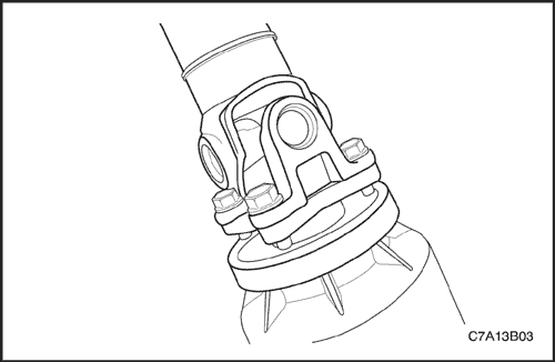
- Remove the intermediate shaft lower pinch bolt. Refer to Section 6C, Power Steering Gear.
- Remove the shift control cable from the auto-transaxle. Refer to Section 5A, AISIN 55-51LE Automatic transaxle, if auto-transaxle.

- Remove the select cable from the transaxle. Refer to Section 5B, Five-Speed Manual Transaxle, if manual-transaxle.
- Remove the transaxle oil cooler hoses from the auto-transaxle. Refer to Section5A, AISIN 55-51LE Automatic transaxle, if auto-transaxle.
- Remove the clutch actuator cylinder pipe from the transaxle. Refer to Section 5B, Five-Speed Manual Transaxle, if manual-transaxle.
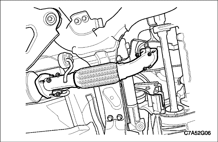
- Remove the front exhaust pipe between the pre-catalyst and the DPF pipe. Refer to Section 1G1, Engine Exhaust-2.0 Diesel.
- Remove the A/C compressor pipe from the compressor. Refer to Section 7B, Manual Control Heating, Ventilation and Air Conditioning System.
- Remove the power steering return cooling pipe. Refer to Section 6A, Power Steering System.
- Remove the propeller shaft assembly from the transfer case, if equipped. Refer to Section 3B, Rear Drive Axle.
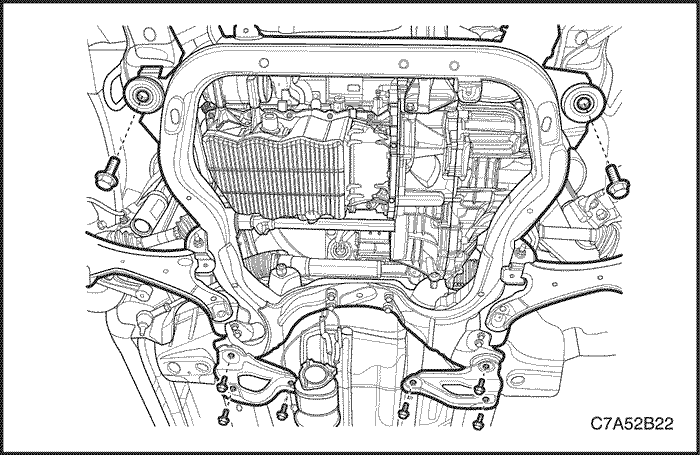
- Remove the cradle supporter bracket.
- Remove the cradle tightening bolts.
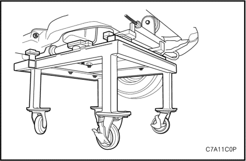
Caution : Make sure that all components have to be set on the exact position on the engine assembly remove/install pallet EN–48243 with the pallet supporter EN–48244 as shown.
- 1~4 : Cradle Supporter
- a : Diesel Engine Oil Pan Supporter
- b : FAM II 2.4D Engine Oil Pan Supporter
- c & d : HFV6 3.2L Engine Oil Pan Supporter
- e : Manual Transaxle Supporter
- f : Automatic Transaxle Supporter
- g : Transfer Case Supporter (M/T & A/T)
- h : Transaxle Mount Supporter (M/T & A/T)

Caution : Only lower the vehicle far enough to take the weight off the engine and transaxle mount, or damage to the mount and pallet/pallet supporter failure may occur.
- Lower the vehicle and position the engine assembly on to the engine assembly remove/install pallet EN–48243 with the pallet supporter EN–48244 to the cradle.
- Remove the engine mount bolt from the engine mount bracket.
- Remove the transaxle mount bolt from the transaxle.
- Tighten the engine assembly using by hoist, etc.
- Remove the transaxle front mount.
- Remove the transaxle rear mount.
- Remove the engine and transaxle.
Installation Procedure
- Install the transaxle to engine assembly.
Tighten
-
- Tighten the transaxle tightening bolts to 75 N•m (55.3 lb–ft).
- Tighten the oil pan flange-to-transaxle bolts to 50 N•m (36.9 lb–ft).
- Install the cradle on the engine assembly remove/install pallet EN–48243 with the pallet supporter EN–48244 and then assemble the engine and the transaxle onto the cradle.
Caution : Make sure that all components have to be set on the exact position on the engine assembly remove/install pallet EN–48243 with the pallet supporter EN–48244.
- Lower the vehicle and position the engine and transaxle assembly with the cradle attached on to the engine assembly remove/install pallet EN–48243 with the pallet supporter EN–48244 to the vehicle.
- Install the transaxle rear mount.
Tighten
Tighten the transaxle rear mount bolt to 90 N•m (66.4 lb–ft).
- Install the transaxle front mount.
Tighten
Tighten the transaxle front mount bolt to 90 N•m (66.4 lb–ft).
- Install the transaxle mount.
Tighten
-
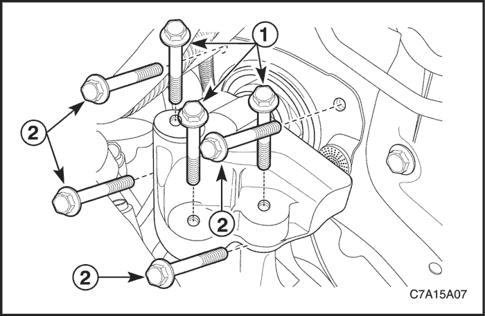
- Tighten the transaxle mount assembly retaining bolts (2) to 37 N•m (27 lb–ft).
- Tighten the transaxle mount bracket retaining bolts (1) to 50 N•m (37 lb–ft).
- Install the engine mount bolt.
Tighten
Tighten the engine mount bracket retaining bolts to 50 N•m (37 lb–ft).
- Remove the engine assembly remove/install pallet EN–48243 with the pallet supporter EN–48244 from the vehicle.
- Install the cradle–to–body mounting bolts. Refer to Section 2C, Front Suspension.
Tighten
Tighten the cradle mounting bolts to 155 N•m (114.3 lb–ft).
- Install the cradle support bracket retaining bolts. Refer to Section 2C, Front Suspension.
Tighten
Tighten the cradle support bracket bolts to 50 N•m (36.9 lb–ft).
- Connect the engine wiring harness.
-
- a) Connect the fuel heat connector.
- b) Connect the mass air flow sensor(MAF) connector.
- c) Connect the exhaust temperature sensor wire connector.
- d) Connect the DPF pressure sensor connector.
- e) Connect the engine oil pressure switch connector.
- f) Connect the common rail pressure sensor connector.
- g) Connect the coolant temperature sensor connector.
- h) Connect the EGR vacuum solenoid connector.
- i) Connect the fuel injector connector.
- j) Connect the camshaft position sensor(CMP) connector.
- k) Connect the turbocharger actuator connector.
- l) Connect the glow plug wire connector.
- m) Connect the booster pressure(T-MAP) sensor connector.
- n) Connect the common rail regulator connector.
- o) Connect the ETC body connector.
- p) Connect the fuel injection pump connector.
- q) Connect the cooling fan connectors.
- r) Connect the A/C compressor connector.
- s) Connect the starter solenoid wire connector.
- t) Connect the A/C pressure sensor connector.
- u) Connect the transaxle range(TR) switch connector, if auto-transaxle.
- v) Connect the transaxle wiring electrical connector, if auto-transaxle.
- w) Connect the input speed sensor electrical connector, if auto-transaxle.
- x) Connect the output speed sensor electrical connector, if auto-transaxle.
- y) Connect the speed sensor connector, if manual-transaxle.
- z) Connect the crankshaft position sensor.
-
- (B) Connect the generator connector.
- Install the engine splice pack tighten bolt onto the intake manifold.
- Install the glow plug module nut.
- Install the glow plug fuse box bolt.
- Install the generator B+ connector nut.
- Install the starter solenoid connector nut.
- Install the engine ground bolt.
Tighten
-
- Tighten the engine wiring harness splice pack tighten bolt to 15 N•m (11.1 lb–ft).
- Tighten the glow plug module retaining nut to 14 N•m (10.3 lb–ft).
- Tighten the glow plug fuse box bolts to 10 N•m (88.5 lb–in).
- Tighten the generator B+ connector nut to 25 N•m (18.4 lb–ft).
-
- Tighten the starter solenoid connector nut to 15 N•m (11.1 lb–ft).
- Tighten the engine block ground bolt to 25 N•m (18.4 lb–ft).
 |
|
 |
|
| © Copyright Chevrolet Europe. All rights reserved |


