MAINTENANCE AND REPAIR
ON-VEHICLE SERVICE


Fuel System Pressure Relief
Procedure
Caution : The fuel system is under pressure. To avoid fuel spillage and the risk of personal injury or fire, it is necessary to relieve the fuel system pressure before disconnecting the fuel lines.
- Remove the fuel cap.
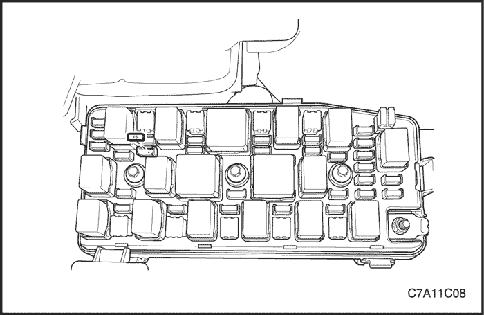
- Remove the fuel pump fuse from the engine fuse block.
- Start the engine and allow the engine to stall.
- Crank the engine for an additional 10 seconds.
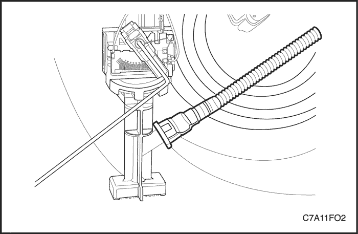
Fuel Pressure Inspection
Tools Required
DW100-010 Fuel Pressure Gauge
Inspection Procedure
Caution : The fuel system is under pressure. To avoid fuel spillage and the risk of personal injury or fire, it is necessary to relieve the fuel system pressure before disconnecting the fuel lines.
- Relieve the fuel system pressure. Refer to "Fuel System Pressure Relief" in this section.
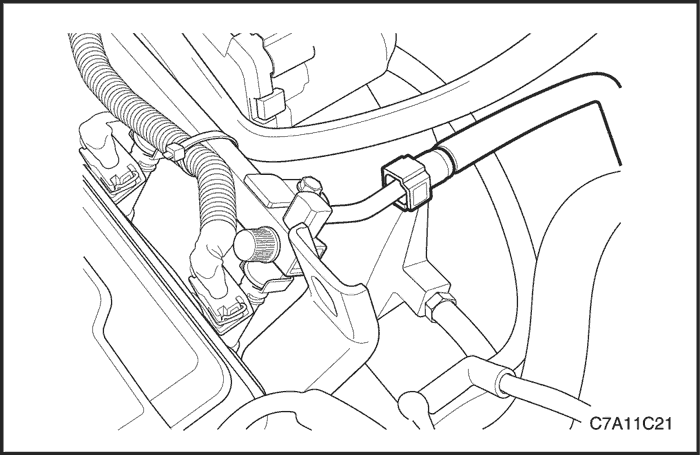
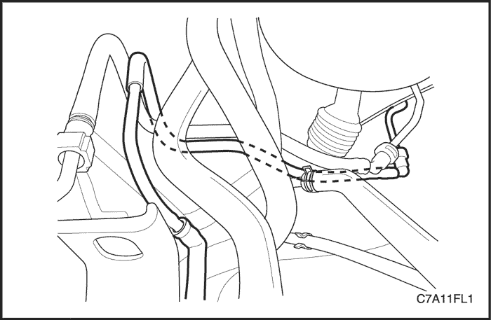
- Disconnect the fuel feed line from the fuel rail.
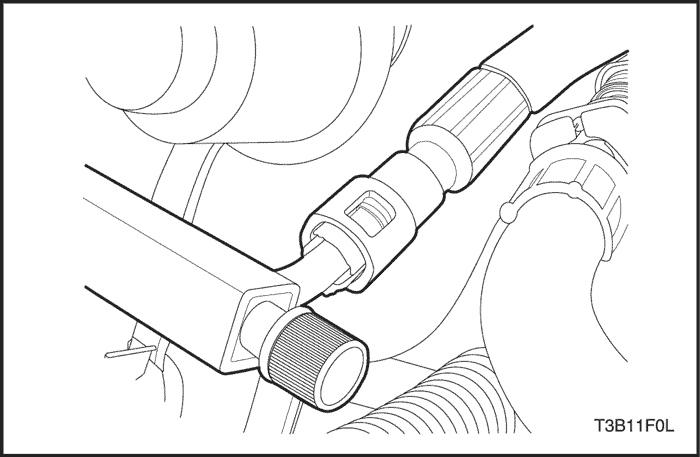
- Connect the fuel pressure gauge connector to the fuel rail.
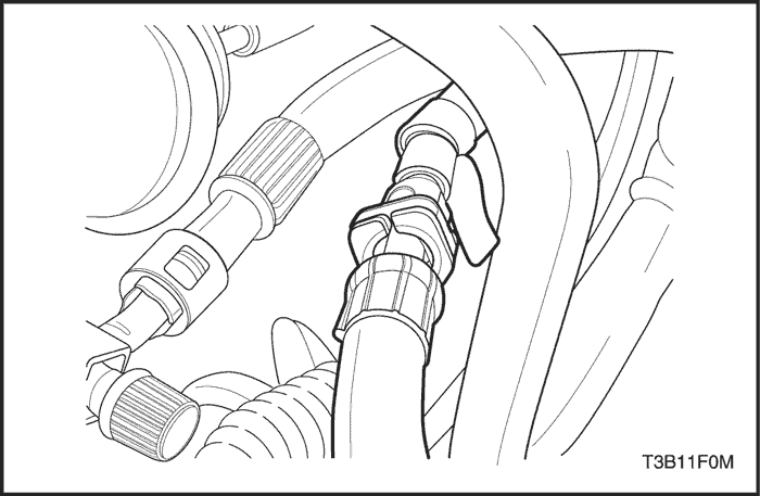
- Connect the fuel pressure gauge connector to the fuel feed line.
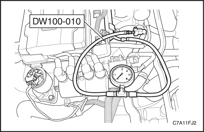
- Check the fuel leakage.
- Read the fuel pressure gauge DW100-010. Normal fuel pressure is between 402 kPa (58.3 psi) to 418 kPa (60.6 psi).
- Relieve the fuel pressure.
- Remove the fuel pressure gauge DW100-010.
- Connect the fuel feed line to the fuel rail.
- Start the engine and check for the fuel leakage.
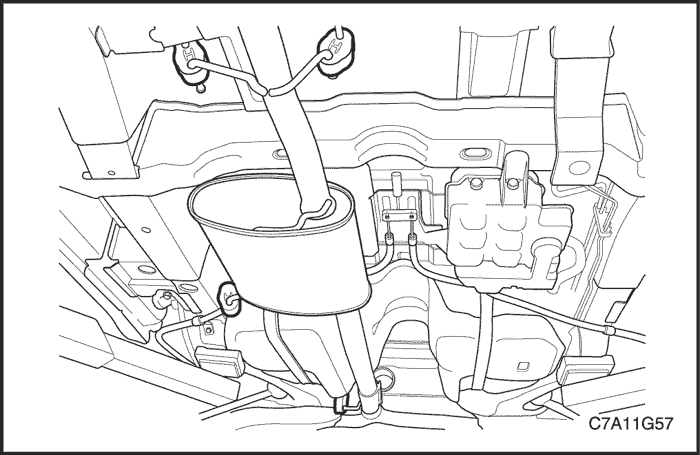
Fuel Tank
Removal Procedure
Caution : Do not allow smoking or the use of open flames in the area where work on the fuel or EVAP system is taking place. Anytime work is being done on the fuel system, disconnect the negative battery cable, except for those tests where battery voltage is required.
Caution : The fuel system is under pressure. To avoid fuel spillage and the risk of personal injury or fire, it is necessary to relieve the fuel system pressure before disconnecting the fuel lines.
- Disconnect the negative battery cable.
- Drain the fuel tank. Ensure that the fuel level in the tank is less than1/4 full. If necessary, drain the fuel tank to at least this level.
- Relieve the fuel system pressure. Refer to "Fuel System Pressure Relief"
in this section.
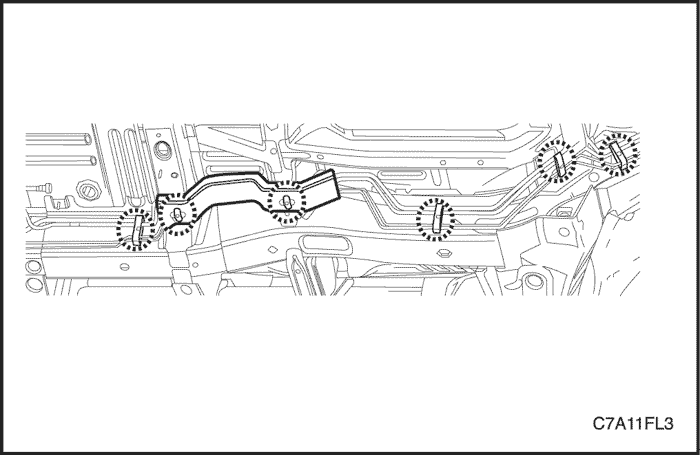
- Raise and support the vehicle.
- Remove the front muffler. Refer to Section 1G2, Engine Exhaust - FAM II 2.4D.
- For the AWD vehicle, remove the propeller shaft and rear drive module (RDM). Refer to Section 3B, Rear Drive Axle.
- Disconnect the fuel pump connector at the right rear side of the fuel tank.
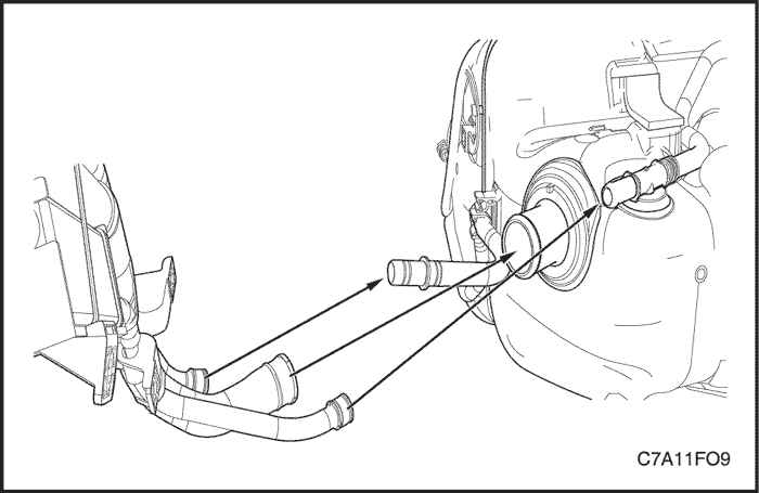
- Disconnect the fuel tank filler tube, EVAP vent hose and vapor hose from the fuel tank.
- Disconnect the fuel feed line near the right front side of the fuel tank.
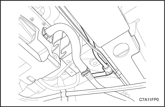
- Disconnect the fuel vapor pipe from the EVAP emission canister.
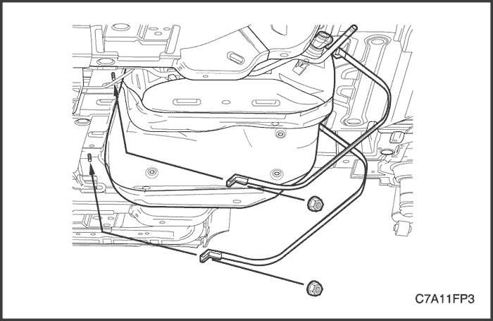
- Support the fuel tank.
- Remove the parking brake cables support bracket bolts and move it away from the fuel tank.
- Remove the fuel tank strap retaining nuts.
- Remove the fuel tank straps.
- Carefully lower the jack and move the front of the fuel pump downward while tilting the rear of the fuel pump upward.
- Remove the fuel tank.
Installation Procedure
- Install the fuel tank in the position previously removed.
- Install the fuel tank straps.
Tighten
Tighten the fuel tank strap retaining nuts to 20 N•m (15 lb-ft).
- Install the parking brake cables support bracket bolts.
- Connect the fuel vapor pipe to the EVAP emission canister.
- Connect the fuel feed line near the right front side of the fuel tank.
- Connect the fuel tank filler tube, EVAP vent hose and vapor hose to the fuel tank.
- Connect the fuel pump connector at the right rear side of the fuel tank.
- Install the parking brake cables support bracket. Refer to Section 4G, Parking Brake.
- Install the front muffler. Refer to Section 1G2, Engine Exhaust - FAM II 2.4D.
- For the AWD vehicle, install the propeller shaft and RDM. Refer to Section 3B, Rear Drive Axle.
- Fill the fuel tank.
- Connect the negative battery cable.
- Perform a leak check of the fuel tank and the fuel line connections.
Fuel Pump Assembly
Tools Required
Main Fuel Pump Locking Ring Remover/Installer EN-48279
Sub Fuel Pump Locking Ring Remover/Installer EN-48278
Removal Procedure
Caution : The fuel system is under pressure. To avoid fuel spillage and the risk of personal injury or fire, it is necessary to relieve the fuel system pressure before disconnecting the fuel lines.
- Relieve the fuel system pressure. Refer to "Fuel System Pressure Relief"
- Disconnect the negative battery cable.
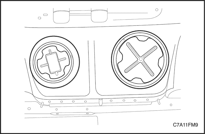
- Fold the rear seat.
- Lift up the carpet and the insulation.
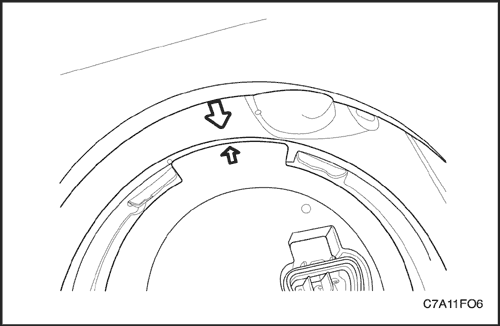
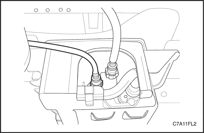
- Remove the main and sub fuel pump access covers.
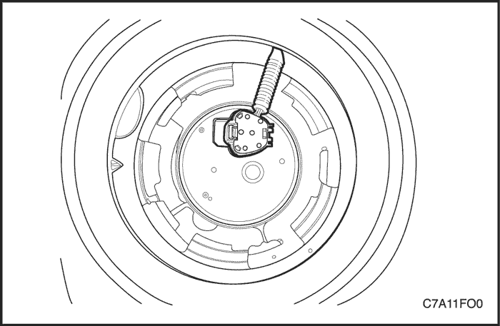
- Disconnect the electrical connector at the sub fuel pump assembly.
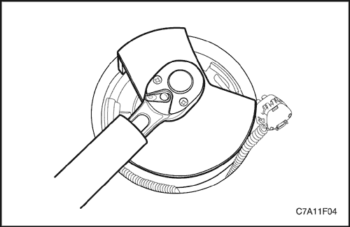
- Install the sub fuel pump lock ring remover/installer EN-48278 to the sub fuel pump and turn it counterclockwise.
- Remove the sub fuel pump lock ring.
Notice : Be careful not to damage the fuel sender for the correct fuel leveling while removing the fuel pump assembly from the fuel tank.
- Remove the sub fuel pump assembly and the O-ring from the fuel tank.
Notice : O-ring should not be contaminated by fuel.
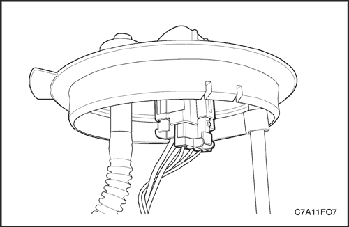
- Disconnect the main fuel pump-to-sub fuel pump connecting hose at the sub fuel pump.
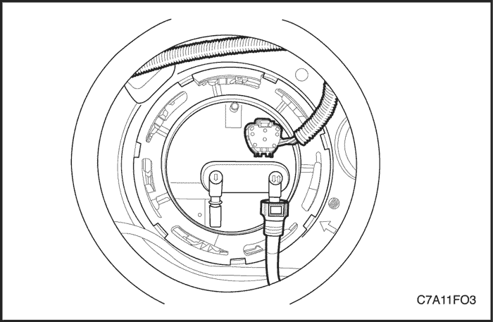
- Disconnect the electrical connector at the main fuel pump assembly.
- Disconnect the fuel feed line.
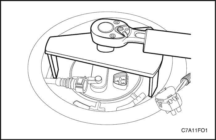
- Install the main fuel pump lock ring remover/installer EN-48279 to the main fuel pump and turn it counterclockwise.
- Remove the main fuel pump lock ring.
Notice : Be careful not to damage the fuel sender for the correct fuel leveling while removing the fuel pump assembly from the fuel tank.
- Remove the main fuel pump assembly and the O-ring from the fuel tank.
Notice : O-ring should not be contaminated by fuel.
Installation Procedure
- Clean all of the mating surface on the both fuel pump and fuel tank.
Notice : For ease of the main fuel pump-to-sub fuel pump connecting hose, install the main fuel pump assembly first.
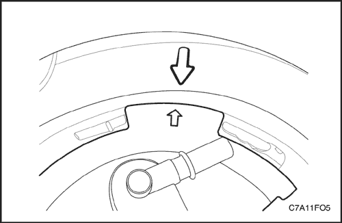
Notice : Be sure that the arrow on the main fuel pump assembly should be aligned with the arrow on the fuel tank.
Notice : Be careful not to damage the fuel sender for the correct fuel leveling while installing the fuel pump assembly to the fuel tank.
Caution : Do not reuse the main fuel pump O-ring.
- Position the new main fuel pump O-ring and the main fuel pump first into the fuel tank in the same location as removed.
- Pull the main fuel pump-to-sub fuel pump connecting hose towards the sub fuel pump assembly.
- Connect the main fuel pump-to-sub fuel pump connecting hose at the sub fuel pump.
Notice : Be sure that the arrow on the sub fuel pump assembly should be aligned with the arrow on the fuel tank.
Notice : Be careful not to damage the fuel sender for the correct fuel leveling while installing the fuel pump assembly to the fuel tank.
Caution : Do not reuse the sub fuel pump O-ring.
- Position the new sub fuel pump O-ring and the sub fuel pump into the fuel tank in the same location as removed.
- Install the sub fuel pump lock ring by turning the sub fuel pump lock ring remover/installer EN-48278 clockwise.
- Connect the electrical connector at the sub fuel pump.
- Install the main fuel pump lock ring by turning the main fuel pump lock ring remover/installer EN-48279 clockwise.
- Connect the electrical connector at the main fuel pump.
- Connect the fuel feed line.
- Install the main and sub fuel pump access covers.
- Connect the negative battery cable.
- Perform an operational check of the fuel pump.
- Fold the rear seat back to the original position.
Fuel Sender
Replacement Procedure
Notice : The illustrations in this section show the fuel sender on the main fuel pump ONLY. The fuel sender on the sub fuel pump is similar.
Notice : Be careful not to damage the fuel sender for the correct fuel leveling while removing or installing the fuel pump assembly from the fuel tank.
- Remove the fuel pump assembly. Refer to "Fuel Pump Assembly" in this section.
- Disconnect the fuel sender connector.
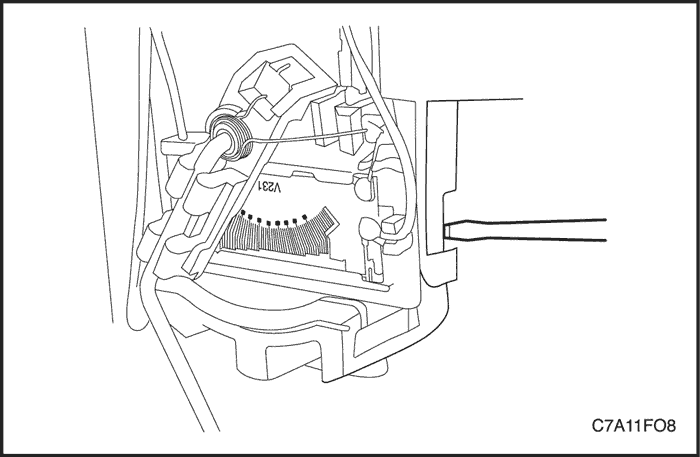
- Press the locking tap by using a suitable tool such as a screwdriver.
- Remove the fuel sender assembly by sliding it out from the fuel pump.
Notice : Improper installation of the fuel sender on the fuel pump may cause the incorrect fuel leveling.
- Install the fuel sender in the reverse order of removal.
- Install the fuel pump assembly into the fuel tank. Refer to "Fuel Pump Assembly"
in this section.
Fuel Filter
Notice : The fuel filter is assembled within the fuel pump. It cannot be replaced separately. The fuel filter should be replaced as a fuel pump assembly, if needed. Refer to "Fuel Pump" in this section.
Fuel Rail and Injectors
Removal Procedure
Caution : the fuel system is under pressure. To avoid fuel spillage and the risk of personal injury or fire, it is necessary to relieve the fuel system pressure before disconnecting the fuel lines.
- Relieve the fuel system pressure. Refer to " Fuel System Pressure Relief " in this section.
- Disconnect the negative battery cable.
- Disconnect the intake air temperature (IAT) sensor connector.
- Loosen the clamp and disconnect the air cleaner outlet hose from the resonator.
- Loosen the clamp and remove the resonator from the electronic throttle body.
- Remove the engine cover.
- Disconnect the breather hose and PCV hose from the cylinder head cover.
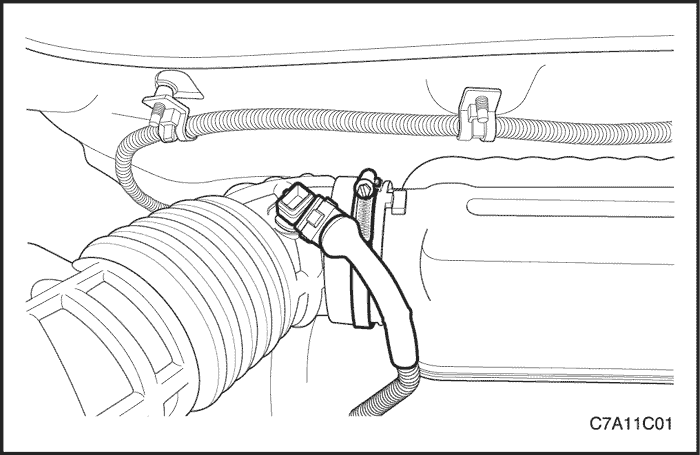
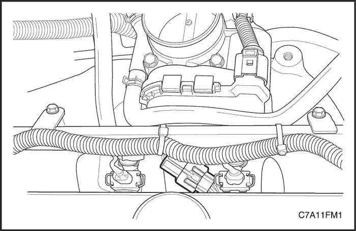
- Disconnect the fuel feed line at the fuel rail.
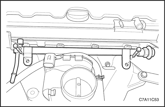
- Connect the fuel injector connectors.
- Remove the fuel rail retaining bolts.
Notice : Before removal, the fuel rail assembly may be cleaned with a spray-type cleaner, following the package instructions. Do not immerse the fuel rails in liquid cleaning solvent. Use care in removing the fuel rail assembly to prevent damage to the electrical connectors and the injector spray tips. Prevent dirt and other contaminants from entering open lines and passages. Fittings should be capped and holes should be plugged during service.
Important : If an injector becomes separated from the rail and remain in the cylinder head, replace the injector O-ring seals and the retaining clip.
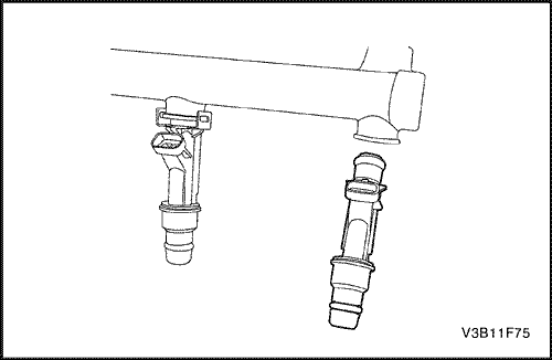
- Remove the fuel rail with the injectors attached.
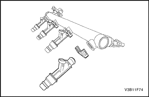
- Remove the fuel injector retainer clips.
- Remove the fuel injectors by pulling them down and out.
- Discard the fuel injector O-rings.
Installation Procedure
Important : Different injectors are calibrated for different flow rates. When ordering new fuel injectors, be certain to order the identical part number that is inscribed on the old injector.
- Lubricate the new fuel injector O-rings with engine oil. Install the new O-rings on the fuel injectors.
- Install the fuel injectors into the fuel rail sockets with the fuel injector terminals facing outward.
- Install the fuel injector retaining clips onto the fuel injector and the fuel rail ledge.
- Make sure that the clips are parallel to the fuel injector harness connector.
- Install the fuel rail assembly into the cylinder head.
- Install the fuel rail retaining bolts.
Tighten
Tighten the fuel rail retaining bolts to 25 N•m (18 lb-ft).
- Connect the fuel injector connectors. Rotate each fuel injector as required.
- Connect the fuel feed line to the fuel rail.
- Install the resonator to the electronic throttle body.
- Connect the air cleaner outlet hose to the resonator.
- Connect the breather hose and PCV hose to the cylinder head cover.
- Connect the IAT sensor connector.
- Install the engine cover.
- Connect the negative battery cable.
- Perform a leak check of the fuel rail and fuel injectors.
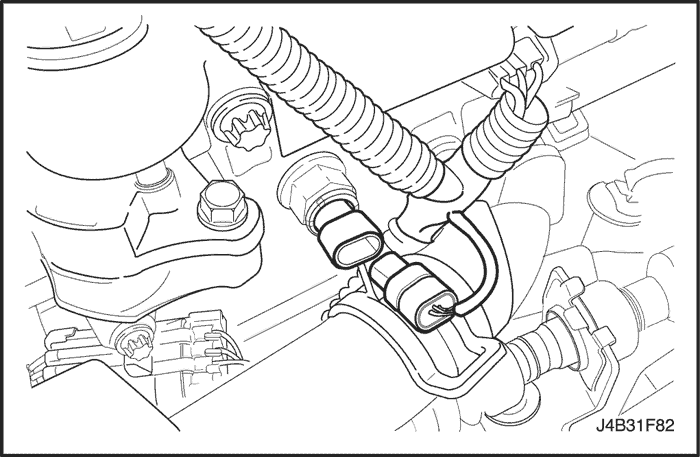
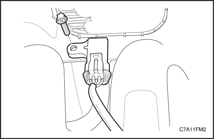
Engine Coolant Temperature (ECT) Sensor
Removal Procedure
- Relieve the coolant system pressure.
- Disconnect the negative battery cable.
- Disconnect the engine coolant temperature (ECT) sensor connector.
Notice : Take care when handling the engine coolant temperature sensor. Damage to the sensor will affect the proper operation of the fuel injection system.
- Remove the ECT sensor from the exhaust gas recirculation (EGR) valve adapter.
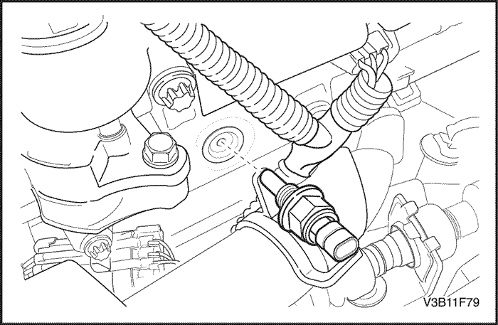
Installation Procedure
- Coat the threads of the ECT sensor with sealer.
- Install the ECT sensor into the EGR valve adapter. adapter.
Tighten
Tighten the engine coolant temperature sensor to 20 N•m (15 lb-ft).
- Connect the ECT sensor connector.
- Fill the coolant system.
- Connect the negative battery cable.
Electronic Throttle Body
Removal Procedure
- Disconnect the negative battery cable.
- Disconnect the intake air temperature (IAT) sensor connector.
- Loosen the clamp and disconnect the air cleaner outlet hose from the resonator.
- Loosen the clamp and remove the resonator from the electronic throttle body.
- Remove the engine cover.
- Disconnect the breather hose and PCV hose from the cylinder head cover.
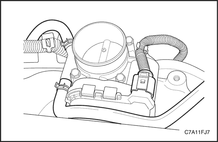
- Disconnect the coolant hoses from the electronic throttle body.
- Disconnect the electronic throttle control (ETC) connector.
Notice : The electronic throttle body control unit must not be removed from the electronic throttle body.
- Remove the electronic throttle body retaining bolts.
- Remove the electronic throttle body and the electronic throttle body gasket.
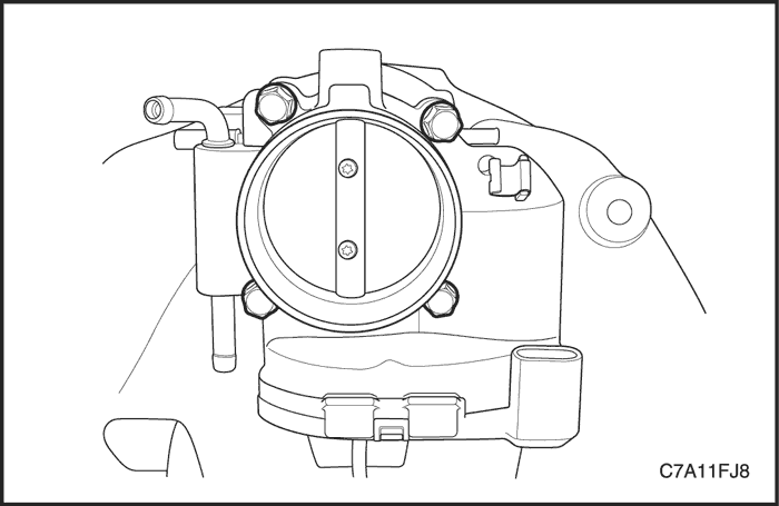
Installation Procedure
Notice : Use care in cleaning old gasket material from the machined aluminum surfaces. Sharp tools may damage sealing surfaces.
- Clean the gasket mating surface on the intake manifold.
Notice : The electronic throttle body may be cleaned in a cold immersion-type cleaner following disassembly.
- Clean the electronic throttle body.
- Install the electronic throttle body assembly with a new gasket to the intake manifold.
- Install the electronic throttle body retaining bolts.
Tighten
Tighten the electronic throttle body retaining bolts to 10 N•m (89 lb-in).
- Connect the ETC connector.
- Connect the coolant hoses to the electronic throttle body.
- Install the resonator to the electronic throttle body.
- Connect the air cleaner outlet hose to the resonator.
- Connect the breather hose and PCV hose to the cylinder head cover.
- Connect the IAT sensor connector.
- Connect the negative battery cable.
- Fill the cooling system.
- Reset all learned values in ECM.

Front Heated Oxygen Sensor
Tools Required
DW170-010 Oxygen Sensor Remover/Installer
Removal Procedure
- Disconnect the negative battery cable.
Notice : The oxygen sensor used a permanently attached pigtail and connector. This pigtail should not be removed from the oxygen sensor. Damage or removal of the pigtail or the connector affect the proper operation of the oxygen sensor. Take care when handing the oxygen sensor. Do not drop the oxygen sensor.
- Disconnect the front heated oxygen sensor connector.
Caution : Allow the engine to cool before removing the oxygen sensor. Removal of the oxygen sensor when the engine is hot may damage the threads in the exhaust manifold.
- Using the oxygen sensor remover/installer DW170-010, carefully remove the front heated oxygen sensor.
Installation Procedure
Important : A special anti-seize compound is used on the oxygen sensor threads. This compound consists of a liquid graphite and glass beads. The graphite will burn away, but the glass beads will remain, making the sensor easier to remove. New or serviced sensors will already have the compound applied to the threads. If a sensor is removed from any engine and is to be reinstalled, the threads must have an anti-seize compound applied before reinstallation.
- Coat the threads of the front heated oxygen sensor with anti-seize compound, if needed.
- Using the oxygen sensor remover/installer DW170-010, install the front heated oxygen sensor into the exhaust manifold.
Tighten
Tighten the front heated oxygen sensor to 50 N•m (37 lb-ft).
- Connect the front heated oxygen sensor connector.
- Connect the negative battery cable.
Rear Heated Oxygen Sensor
Tools Required
DW170-010 Oxygen Sensor Remover/Installer
Removal Procedure
- Disconnect the negative battery cable.
Notice : The oxygen sensor used a permanently attached pigtail and connector. This pigtail should not be removed from the oxygen sensor. Damage or removal of the pigtail or the connector affect the proper operation of the oxygen sensor. Take care when handing the oxygen sensor. Do not drop the oxygen sensor.
- Disconnect the rear heated oxygen sensor connector.
Caution : Allow the engine to cool before removing the oxygen sensor. Removal of the oxygen sensor when the engine is hot may damage the threads in the exhaust manifold.
- Using the oxygen sensor remover/installer DW170-010, carefully remove the rear heated oxygen sensor.
Installation Procedure
Important : A special anti-seize compound is used on the oxygen sensor threads. This compound consists of a liquid graphite and glass beads. The graphite will burn away, but the glass beads will remain, making the sensor easier to remove. New or serviced sensors will already have the compound applied to the threads. If a sensor is removed from any engine and is to be reinstalled, the threads must have an anti-seize compound applied before reinstallation.
- Coat the threads of the rear oxygen sensor with anti-seize compound, if needed.
- Using the oxygen sensor remover/installer DW170-010, install the rear heated oxygen sensor into the exhaust front pipe.
Tighten
Tighten the rear heated oxygen sensor to 50 N•m (37 lb-ft).
- Connect the rear heated oxygen sensor connector.
- Connect the negative battery cable.
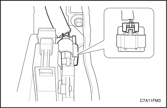
Accelerator Pedal Module (APM)
Removal Procedure
- Disconnect the negative battery cable.
- Disconnect the accelerator pedal module (APM) connector locking tab from the APM connector.
- Disconnect the APM connector.
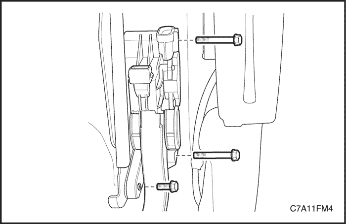
- Remove the bolts, three places, attaching the APM from the accelerator and brake pedal module bracket.
Installation Procedure
- Install the APM retaining bolts to the accelerator and brake pedal module bracket.
Tighten
Tighten the accelerator pedal module retaining bolts to 9 N•m (80 lb-in).
- Connect the APM connector and the install the locking tab firmly.
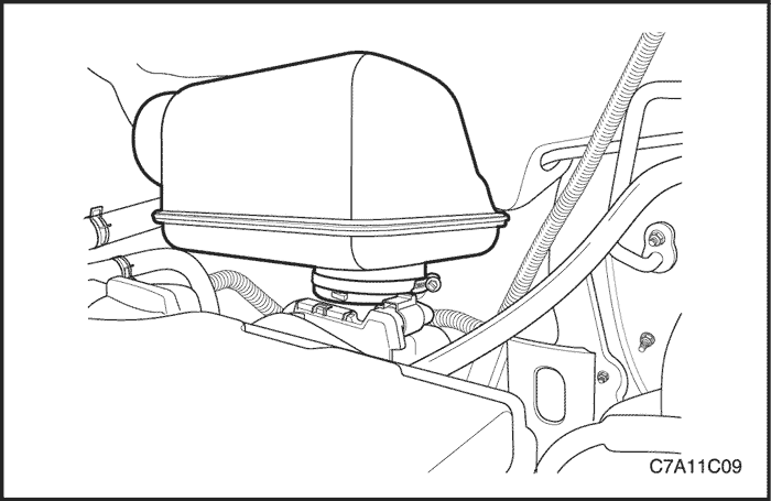
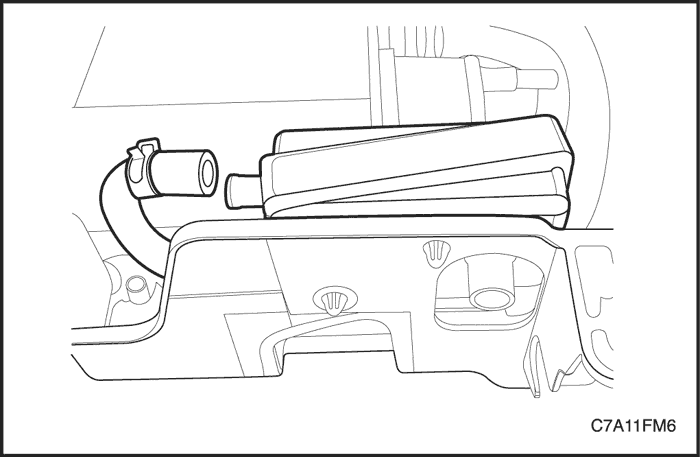
Intake Air Temperature (IAT) Sensor
Removal Procedure
Caution : Do not remove the IAT sensor from the air cleaner outlet hose. Replace only the air cleaner outlet hose assembly with the IAT sensor attached, if necessary.
- Disconnect the negative battery cable.
- Disconnect the intake air temperature (IAT) sensor connector.
- Loosen the both clamp at the air cleaner outlet hose and replace the air cleaner outlet hose assembly with the IAT sensor attached.
Installation Procedure
- Install the air cleaner outlet hose with the IAT sensor attached.
- Connect the IAT sensor connector.
- Connect the negative battery cable.
Manifold Absolute Pressure (MAP) Sensor
Removal Procedure
- Disconnect the negative battery cable.
- Disconnect the intake air temperature (IAT) sensor connector.
- Loosen the clamp and disconnect the air cleaner outlet hose from the resonator.
- Loosen the clamp and remove the resonator from the electronic throttle body.
- Remove the fuel rail. Refer to "Fuel Rail and Injectors"
in this section.
- Disconnect the manifold absolute pressure (MAP) sensor connector.
- Remove the MAP sensor retaining bolt.
- Remove the MAP sensor from the intake manifold.
Installation Procedure
- Install the MAP sensor to the intake manifold.
- Install the MAP sensor retaining bolt.
Tighten
Tighten the manifold absolute pressure sensor retaining bolt to 4 N•m (35 lb-in).
- Install the fuel rail. Refer to "Fuel Rail and Injectors"
in this section.
- Connect the MAP sensor connector.
- Install the resonator to the electronic throttle body.
- Connect the air cleaner outlet hose to the resonator.
- Connect the IAT sensor connector.
- Connect the negative battery cable.
Exhaust Gas Recirculation (EGR) Valve
Removal Procedure
- Disconnect the negative battery cable.
- Disconnect the EGR valve connector.
- Remove the EGR valve retaining bolts.
- Remove the EGR valve and the gasket from the EGR valve adapter.
Installation Procedure
- Clean the EGR valve adapter mating surface.
- Install a new EGR valve gasket.
- Install the EGR valve with the bolts.
Tighten
Tighten the exhaust gas recirculation valve retaining bolts to 30 N•m (22 lb-ft).
- Connect the EGR valve connector.
- Connect the negative battery cable.
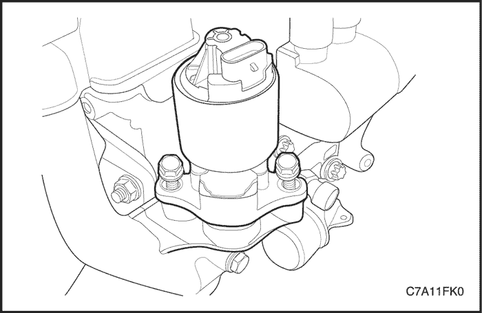
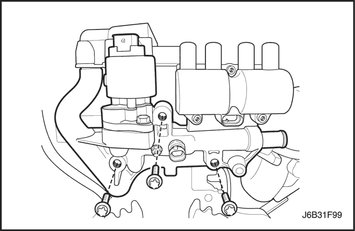
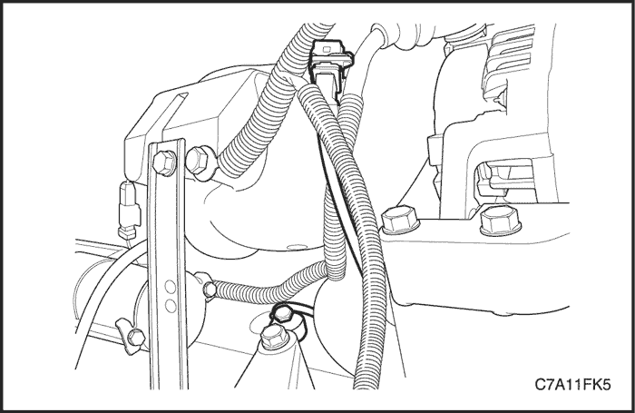
Exhaust Gas Recirculation (EGR) Valve Adapter and Internal PCV Pipe
Removal Procedure
- Disconnect the negative battery cable.
Caution : To prevent personal injury, do not remove the surge tank cap while the engine and the radiator are hot because the heat causes the system to remain under pressure. Scalding fluid and steam may be blown out under pressure.
- Drain the coolant fluid. Refer to Section 1D2, Engine Cooling - FAM II 2.4D.
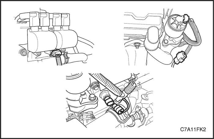
- Remove the engine cover.
- Remove the ignition wires from the direct ignition system (DIS).
- Disconnect the exhaust gas recirculation (EGR) valve connector, engine coolant temperature (ECT) sensor connector and the DIS connector.
- Disconnect the heater return hose at the EGR valve adapter.
- Remove the EGR valve adapter retaining bolts.
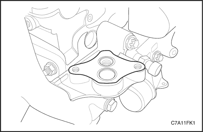
- Remove the EGR valve adapter and the internal PCV pipe with the gasket.
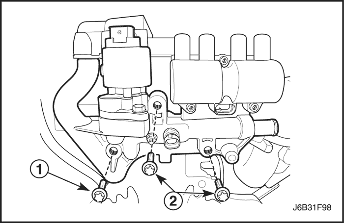
Installation Procedure
- Install the EGR valve adapter and internal PCV pipe with the gasket.
- Install the EGR valve adapter retaining bolts.
Tighten
Tighten the EGR valve adapter retaining bolts (1) to 20 N•m (15 lb-ft).
Tighten the EGR valve adapter retaining bolts (2) to 30 N•m (22 lb-ft).
- Connect the heater return hose to the EGR valve adapter.
- Connect the EGR valve connector, ECT sensor connector and the DIS connector
- Connect the ignition wire to the DIS system.
- Install the engine cover.
- Connect the negative battery cable.
- Fill the coolant system.
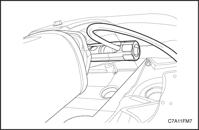
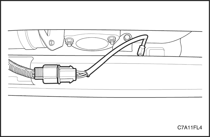
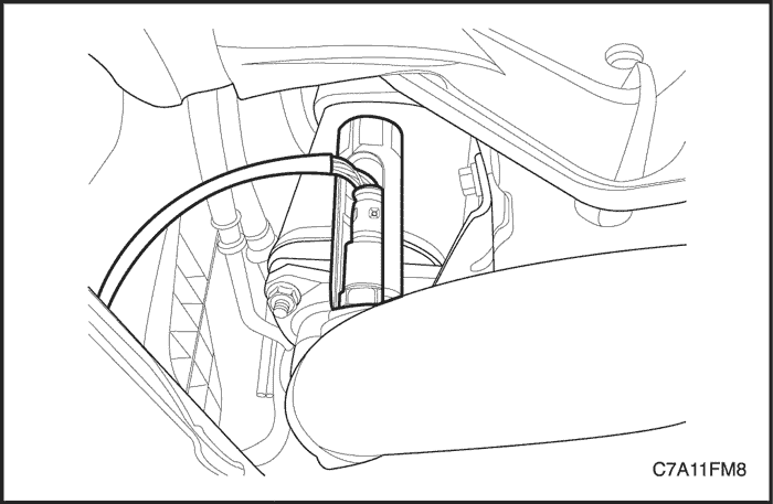
Knock Sensor
Removal Procedure
- Disconnect the negative battery cable.
- Raise and suitably support the vehicle.
- Disconnect the knock sensor connector.
- Remove the knock sensor retaining bolt.
- Remove the knock sensor.
Installation Procedure
- Install the knock sensor with the bolt.
Tighten
Tighten the knock sensor retaining bolt to 20 N•m (15 lb-ft).
- Connect the knock sensor connector.
- Lower the vehicle.
- Connect the negative battery cable.
Evaporative (EVAP) Emission Canister Assembly
Removal Procedure
Caution : Canister and vacuum hoses contain the fuel vapors. Do not smoke in the area or permit an open flame.
- Disconnect the canister fuel vapor hoses from the canister.
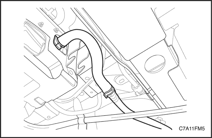
- Loosen the clamp and disconnect the evaporative (EVAP) emission canister vent hose from the EVAP emission canister filter.
- Remove the EVAP emission canister bracket retaining nuts and the EVAP emission canister assembly.
- Separate the canister from the EVAP emission canister bracket.
- Remove the canister.
Installation Procedure
- Install the EVAP emission canister onto the EVAP emission canister bracket.
- Install the EVAP emission canister assembly.
Tighten
Tighten the evaporative emission canister bracket retaining nuts to 10 N•m (89 lb-in).
- Connect the EVAP emission canister vent hose to the EVAP emission canister filter.
- Connect the canister fuel vapor hoses to the canister.
Evaporative (EVAP) Emission Canister Purge Solenoid Valve
Removal Procedure
- Disconnect the negative battery cable.
- Disconnect the evaporative (EVAP) emission canister purge solenoid valve connector.
- Disconnect the vacuum hoses from the EVAP canister purge solenoid.
- Remove the EVAP canister purge solenoid valve bracket bolt from the intake manifold.
- Unclip the EVAP canister purge solenoid valve from the mounting bracket.
Installation Procedure
- Attach the EVAP canister purge solenoid valve to the mounting bracket.
- Install the EVAP canister purge solenoid valve and the mounting bracket to the intake manifold with the bracket bolt.
Tighten
Tighten the evaporative emission canister purge solenoid valve bracket bolt to 5 N•m (44 lb-in).
- Connect the vacuum hoses to the EVAP canister purge solenoid valve.
- Connect the EVAP canister purge solenoid valve connector.
- Connect the negative battery cable.
Evaporative (EVAP) Emission Canister Filter
Removal Procedure
- Remove the EVAP emission canister assembly. Refer to "Evaporative Emission Canister Assembly"
in this section.
- Loosen the clamp and disconnect the EVAP emission canister vent hose from the EVAP emission canister filter.
- Remove the EVAP canister emission canister filter by unclipping the clips from the EVAP emission canister bracket.
Installation Procedure
- Install the EVAP emission canister filter to the EVAP emission canister bracket.
- Connect the EVAP emission canister vent hose to the EVAP emission canister filter.
- Install the EVAP emission canister assembly. Refer to "Evaporative Emission Canister Assembly"
in this section.
Evaporative (EVAP) Emission Pipe Assembly
Removal Procedure
- Disconnect the negative battery cable.
- Disconnect the EVAP emission canister purge front hose from the EVAP emission canister purge solenoid valve.
- Disconnect the EVAP emission canister purge front hose from the EVAP emission pipe.
- Disconnect the EVAP emission pipe rear hose from the EVAP emission canister.
- Remove the EVAP emission canister vapor pipe protector bracket.
- Remove the EVAP emission canister vapor pipe retaining clips.
- Remove the EVAP emission canister vapor pipe.
Installation Procedure
- Install the EVAP emission canister vapor pipe with the retaining clips.
- Install the EVAP emission canister vapor pipe retaining clips.
- Install the EVAP emission canister vapor pipe protector bracket.
- Connect the EVAP emission pipe rear hose to the EVAP emission canister.
- Connect the EVAP emission canister purge front hose to the EVAP emission canister pipe.
- Connect the EVAP emission canister purge front hose to the EVAP emission canister purge solenoid valve.
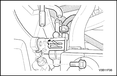
Crankshaft Position (CKP) Sensor
Removal Procedure
- Disconnect the negative battery cable.
- Remove the power steering pump. Refer to Section 6B, Power Steering Pump.
- Remove the A/C compressor. Refer to Section 7B, Manual Control Heating, Ventilation and Air Conditioning System.
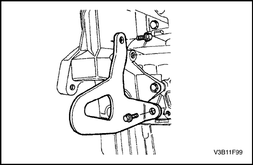
- Remove the rear A/C compressor mounting bracket bolts and the rear A/C compressor mounting bracket.
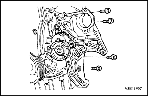
- Remove the accessory mounting bracket by removing the bolts.
- Disconnect the crankshaft position (CKP) sensor connector.
- Remove the CKP sensor retaining bolt.
- Gently rotate and remove the CKP sensor from the engine block.
Installation Procedure
- Install the CKP sensor into the engine block.
- Install the CKP sensor retaining bolt.
Tighten
Tighten the CKP sensor retaining bolt to 8 N•m (71 lb-in).
- Connect the CKP sensor connector.
- Install the accessory mounting bracket with the bolts.
Tighten
Tighten the accessory mounting bracket bolts to 37 N•m (27 lb-ft).
- Install the rear A/C mounting bracket.
Tighten
Tighten the rear A/C mounting bracket bolts to 35 N•m (26 lb-ft).
- Install the A/C compressor. Refer to Section 7B, Manual Control Heating, Ventilation and Air Conditioning System.
- Install the power steering pump. Refer to Section 6B, Power Steering Pump.
- Connect the negative battery cable.
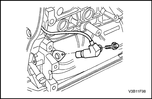
Camshaft Position (CMP) Sensor
Removal Procedure
- Disconnect the negative battery cable.
- Remove the engine cover.
- Disconnect the camshaft position (CMP) sensor connector.

- Remove the timing belt front cover. Refer to Section 1C1, Engine Mechanical - FAM II 2.4D.
- Remove the CMP sensor bolts.
- Remove the CMP sensor from the top.
Installation Procedure
- Install the CMP sensor with the bolts.
Tighten
Tighten the camshaft position sensor bolts to 8 N•m (71 lb-in).
- Install the timing belt front cover. Refer to Section 1C1, Engine Mechanical - FAM II 2.4D.
- Connect the CMP sensor connector.
- Install the engine cover.
- Connect the negative battery cable.
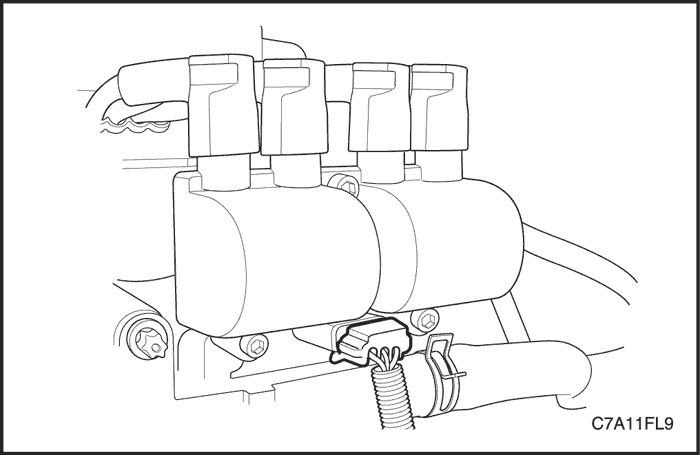
Direct Ignition System (DIS)
Removal Procedure
- Disconnect the negative battery cable.
- Disconnect the direct ignition system (DIS) connector.
- Note the ignition wires' location and remove the ignition wires.
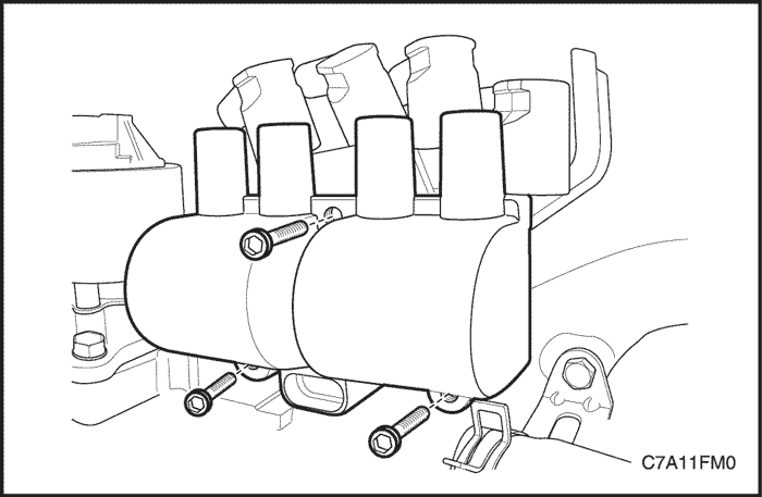
- Remove the DIS retaining bolts.
- Remove the DIS.
Installation Procedure
- Install the DIS into the mounting location and install the retaining bolts.
Tighten
Tighten the direct ignition system retaining bolts to 10 N•m (89 lb-in).
- Connect the DIS connector.
- Install the ignition wires.
- Connect the negative battery cable.
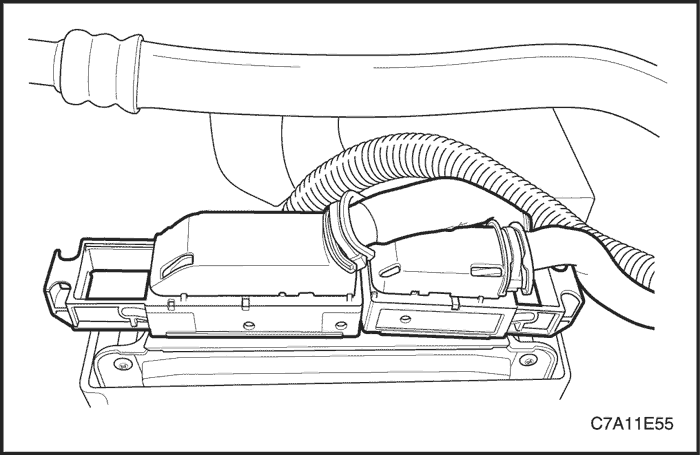
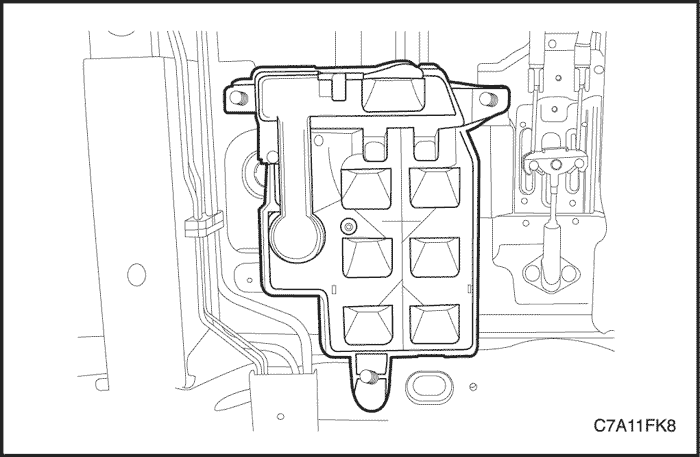
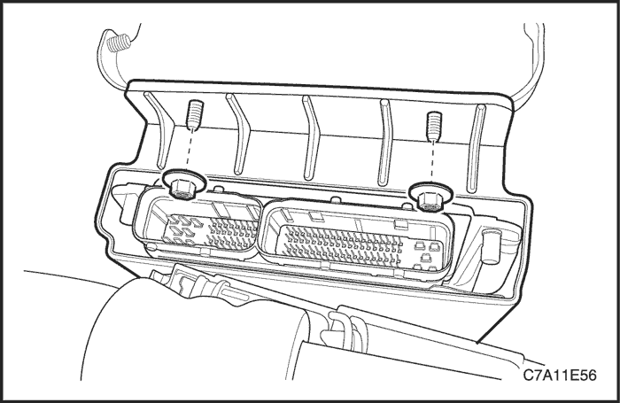
Engine Control Module (ECM)
Removal Procedure
- Disconnect the negative battery cable.
- Disconnect the engine control module (ECM) connectors from the ECM.
- Remove the ECM bracket retaining nuts.
- Remove the ECM with the bracket attached from the battery tray.
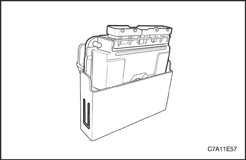
- Unclip the ECM to the bracket and separate the ECM from the bracket.
Installation Procedure
- Install the ECM into the bracket.
- Install the ECM with the bracket attached to the battery tray.
Tighten
Tighten the ECM bracket retaining nuts to 15 N•m (11 lb-ft).
- Connect the ECM connectors to the ECM.
- Connect the negative battery cable.
Caution : If the ECM has been replaced, perform the ECM reprogramming process.
| © Copyright Chevrolet Europe. All rights reserved |


