SECTION 2C
FRONT SUSPENSION
Caution : Disconnect the negative battery cable before removing or installing any electrical unit or when a tool or equipment could easily come in contact with exposed electrical terminals. Disconnecting this cable will help prevent personal injury and damage to the vehicle. The ignition must also be in LOCK unless otherwise noted.
SPECIFICATIONS
Fastener Tightening Specifications
Application | N•m | Lb-Ft | Lb-In |
Front Strut to Knuckle Nuts | 180 | 133 | - |
Font Strut Upper to Body Nuts | 30 | 22 | - |
Stabilizer Link Nuts | 65 | 48 | - |
Control Arm to Cradle Front Nut | 120 | 89 | - |
Control Arm Joint to Knuckle Nut | 10 | - | 89 |
Control Arm Cradle Rear Nuts | 70 | 52 | - |
Front Hub Hub to Knuckle Bolts | 115 | 85 | - |
Brake Hose Bracket to Strut Bolt | 15 | 11 | - |
Front Disc to Hub Detent Screw | 5 | - | 44 |
Outer Tie Rod to Knuckle Nut | 50 | 37 | - |
Hub Nut Onto Axle Shaft | 205 | 157 | - |
Stablizer Shaft Clamp to Cradle Bolts | 50 | 37 | - |
Cradle to Body Bolts | 155 | 114 | - |
Cradle Support Bracket to Body Bolts | 50 | 37 | - |
Cradle to T/M Rear Mount Bolts | 110 | 81 | - |
T/M Front Mount to T/M Bolt | 50 | 37 | - |
Cradle to T/M Front Mount Bolt | 110 | 81 | - |
Power Steering Gear to Cradle Bolts | 110 | 81 | - |
Wheel Nuts | 125 | 92 | - |
Ball Joint to Control Arm Bolts | 68 | 50 | - |
Strut Shaft Nut | 75 | 55 | - |
SPECIAL TOOLS
Special Tools Table
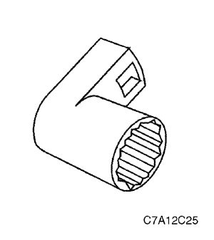
 
| J 42991 Strut Rod Nut Socket |
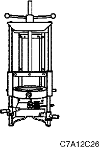
| J 45400 Strut Spring Compressor |
DIAGNOSIS
Shock Absorber
Struts Seem Weak
Checks | Action |
Check the tire pressures. | Adjust the tire pressures to the specifications on the tire placard. |
Check the load conditions under which the vehicle is normally driven. | Consult with the owner to confirm the owner's understanding of normal load conditions. |
Check the compression and rebound effectiveness of the shock absorber. | Quickly push down and then lift up on the corner of the bumper nearest the shock absorber being tested. Compare the compression and rebound with those of a similar vehicle that has an acceptable ride quality. Replace the shock absorber, if needed. |
Struts Are Noisy
Checks | Action |
Check the mountings for looseness or damage. | Tighten the shock absorber mounting nuts. Replace the shock absorber, if needed. |
Check the compression and rebound effectiveness of the shock absorber. | Quickly push down and then lift up on the corner of the bumper nearest the shock absorber being tested. Compare the compression and rebound with those of a similar vehicle that has an acceptable ride quality. Replace the shock absorber, if needed. |
Leaks
Checks | Action |
Check for a slight trace of fluid. | The shock absorber is OK. |
Check the seal cover on the fully extended strut. | Replace the shock absorber. |
Check for an excessive amount of fluid on the shock absorber. | Replace the shock Absorber. |
Ball Joint and Knuckle
Ball Joint Inspection
- Raise the front of the vehicle to allow the front suspensionto hang free.
- Grasp the tire at the top and the bottom.
- Move the top of the tire in an in-and-out motion.
- Look for any horizontal movement of the knuckle relativeto the control arm.
- Ball joints must be replaced under the following conditions:
- The joint is loose.
- The ball seal is cut.
- The ball stud is disconnected from the knuckle.
- The ball stud is loose at the knuckle.
- The ball stud can be twisted in its socket with finger pressure.
Ball Stud Inspection
Make sure to check the tightness of the ball stud in theknuckle boss during each inspection of the ball joint. One way to inspect the ball stud for wear is to shake the wheel and feel for movement of the stud end at the knuckle boss.
Another way to inspect the ball stud for wear is to checkthe fastener torque at the pinch nut. A loose nut can indicate a stressed stud or a hole in the knuckle boss.
Worn or damaged ball joints and knuckles must be replaced.
Excessive Fiction Check
Use the following procedure to check for excessive frictionin the front suspension:
- With the help of another technician, lift up on the frontbumper, raising the vehicle as high as possible.
- Slowly release the bumper.
- Measure the distance from the street level to the center of the bumper.
- Push down on the bumper, release slowly.
- Measure the distance from the street level to the center of the bumper.
- The difference between the two measurements shouldbe less than 13 mm (0.5 inch). If the difference exceedsthis limit, inspect the control arms, the struts, and the ball joints for damage or wear.
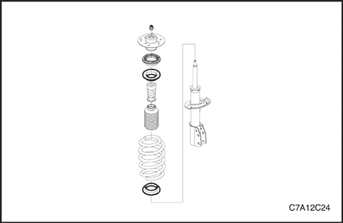
COMPONENT LOCATOR
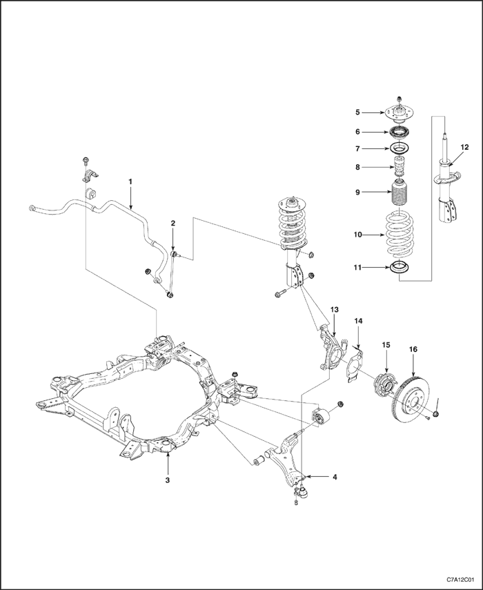
Front Suspension
- Stabilizer Bar
- Stabilizer Link
- Cradle
- Control Arm
- Strut Mount
- Spring Upper Insulator
- Spring Upper Seat
- Hollow Bumper
- Piston Rod Boot
- Coil Spring
- Spring Lower Seat
- Front Strut
- Front Knuckle
- Brake Dust Cover
- Front Hub Unit
- Front DISC
MAINTENANCE AND REPAIR
ON-VEHICLE SERVICE
Front Strut
Removal Procedure
- Raise and suitable support the vehicle.
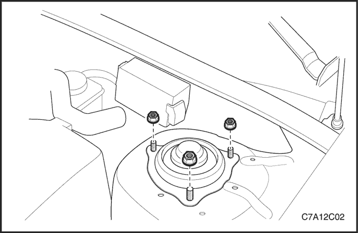
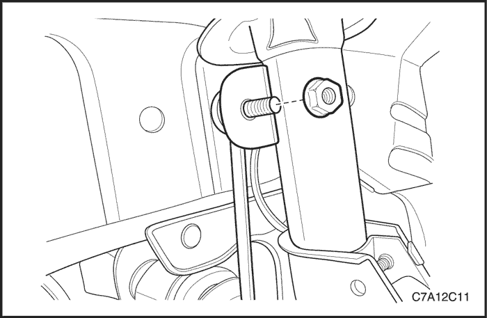
- Remove the cap and nuts from the strut upper area.
- Remove the wheels. Refer to Section 2E, Tires and Wheels.
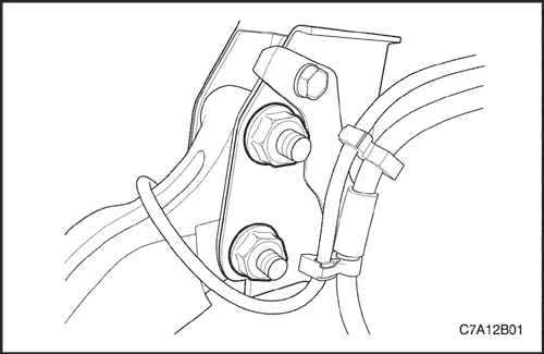
- Remove the brake hose bracket bolt.
- Remove the strut bracket to knuckle bolts and nuts.
- Remove the stabilizer link to strut upper nut.
- Remove the strut assembly.
Installation Procedure
- Install the strut assembly to knuckle bolts and nuts.
Tighten
Tighten the strut assembly bolts and nuts to 180 N•m(133 lb-ft).
- Install the brake hose bracket to strut.
Tighten
Tighten the brake hose bracket bolt to 15 N•m(11 lb-ft).
- Install the cap and nuts from the strut upper areas.
Tighten
Tighten the front strut upper to body nuts to 30 N•m(22 lb-ft).
- Install the stabilizer link to strut upper nut. Refer to "Stabilizer Link" in this section.
- Install the wheels.
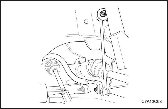
Stabilizer Link
Removal Procedure
- Raise and suitable support the vehicle.
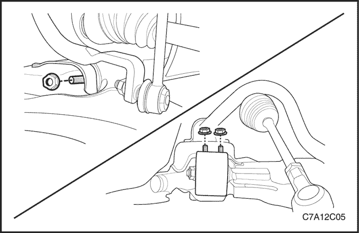
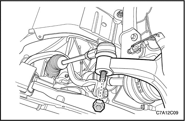
- Remove the stabilizer shaft-to-stabilizer link nut.
- Remove the stabilizer link-to-strut nut.
- Remove the stabilizer link.
Installation Procedure
- Install the stabilizer link and nuts.
- Lower the vehicle.
Tighten
Tighten the stabilizer link nuts to 65 N•m(48 lb-ft).
Front Control Arm
Removal Procedure
- Raise and suitably support the vehicle. Let the control arms hang free.
- Remove the wheel. Refer to Section 2E, Tires and Wheels.
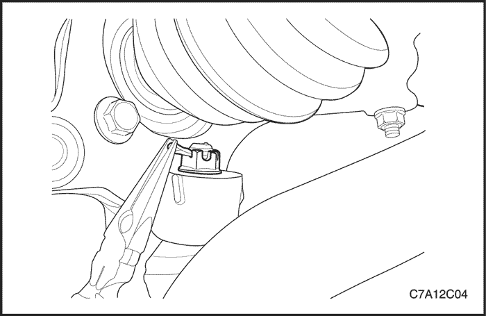
- Remove the control arm joint to knuckle nut and a pin.
- Disconnect the ball joint from the knuckle assembly.
- Remove the control arm to cradle bolts and nuts.
- Remove the control arm.
Installation Procedure
- Install the control arm to cradle front bolt and nut.
Tighten
Tighten the control arm front bolt and nut to 120 N•m(89 lb-ft).
- Install the control arm to cradle rear bolts and nuts.
Tighten
Tighten the control arm rear bolts and nuts to 70 N•m (52 lb-ft).
- Install the control arm joint to knuckle nut and a pin.
Tighten
Tighten the control arm joint bolt to 10 N•m (89 lb-in).
Knuckle, Hub
Removal Procedure
- Remove the wheel.
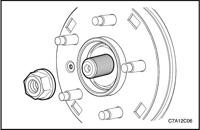
- Remove the hub nut.
- Remove the outer tie rod. Refer to Section 6C, Power Steering Gear.
- Disconnect the control arm ball joint. Refer to "Front Control Arm" in this section.
- Remove the brake caliper. Refer to Section 4D, Front Brakes.
- Remove the detent screw from the brake disc. Remove the disc.
- Remove the front strut to knuckle nuts and bolts.
- Remove the knuckle, hub assembly.

- Remove the hub bolts from the knuckle and separate the hub from the knuckle.
Installation Procedure
- Install the hub to knuckle bolts.
Tighten
Tighten the hub to knuckle bolts to 115N•m (85 lb-ft).
- Install the detent screw and disc.
Tighten
Tighten the detent screw to 5 N•m (3.5 lb-ft).
- Install the brake caliper. Refer to Section 4D, Front Brakes.
- Install the knuckle to strut bolts and nuts.
Tighten
Tighten the knuckle to strut bolts and nuts to 180 N•m (133 lb-ft).
- Install the control arm ball joint to knuckle nut and a pin. Refer to "Front Control Arm" in this section.
- Install the outer tie rod to knuckle nut.
Tighten
Tighten the outer tie rod nut to 50 N•m(37 lb-ft).
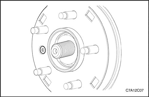
- Install the hub nut onto the axle shaft.
Tighten
Tighten the hub nut onto the axle shaft to 205 N•m (157 lb-ft).
Cradle, Stabilizer Shaft
Removal Procedure
- Raise and suitably support the vehicle and remove the wheels.
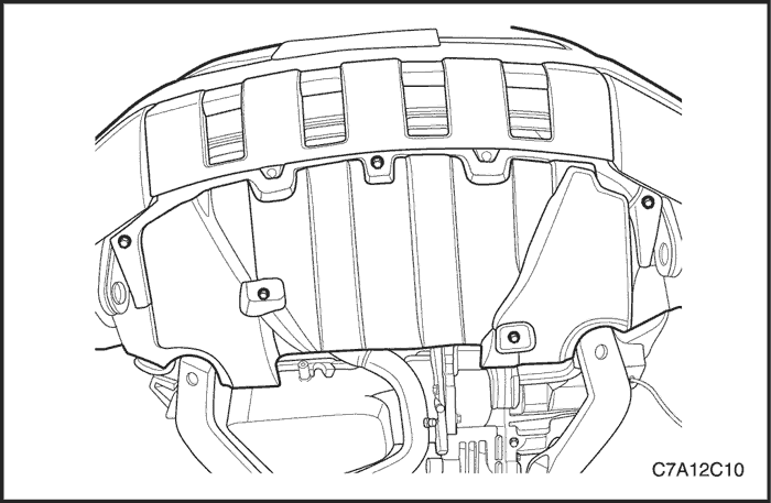
- Remove the dust cover from the under body of the vehicle.
- Remove the front control arm ball joint to knuckle nut and pin.
- Remove the front exhaust muffler and catalytic converter. Refer to Section 1G2, Engine Exhaust.
- Incase of 4 wheel drive vehicle, Remove the propeller shaft.
- Remove the outer tie rod to knuckle nut.
- Remove the stabilizer shaft link to strut nut.
Important : Do not allow the radiator to swing after removing the cradle. The upper part of the radiator should be fixed using strings.
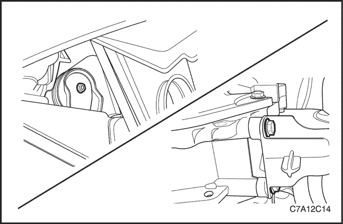
- Remove the power steering gear to cradle bolts.
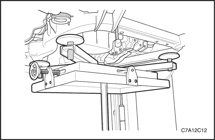
- Support the cradle by a jack stand.
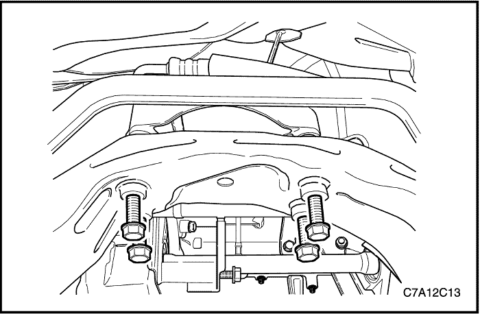
- Remove the cradle to transmission rear mount bracket bolts.
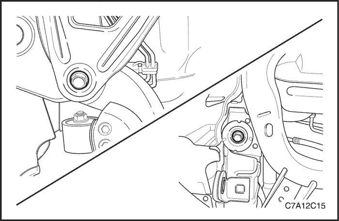
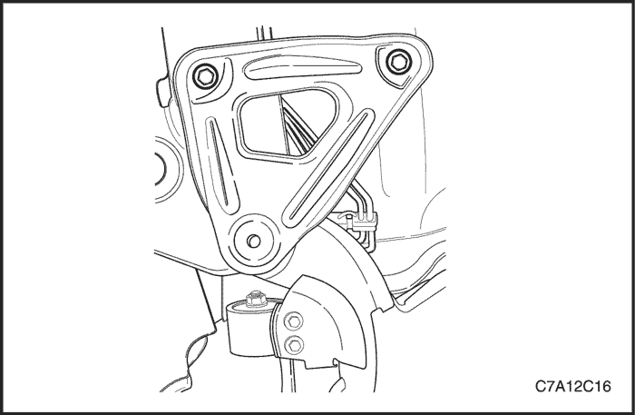
- Remove the transmission front mount to cradle bolt and remove the mount.
- Remove the cradle to body bolts.
- Remove the cradle support bracket to body bolts.
- Lower the cradle slowly with care. Rotate the stabilizer shaft and tie rod properly to have enough spece during lowering the cradle.
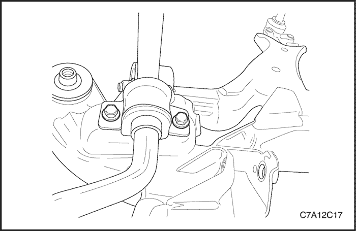
- Remove the stabilizer shaft clamp to cradle bolts.
- Remove the control arm to cradle bolts and nuts. Refer to "Front Control Arm" in this section.
Installation Procedure
- Install the front control arm to cradle bolts and nuts. Refer to "Front Control Arm" in this section.
- Install the stabilizer shaft clamp to cradle bolts.
Tighten
Tighten the stabilizer shaft clamp bolts to 50 N•m (37 lb-ft).
- Raise the cradle slowly with care using a jack stand. Rotate the stabilizer shaft and tie rod properly to settle the cradle in the correct position.
- Install the cradle support bracket and cradle to body bolts.
Tighten
Tighten the cradle to body bolts to 155 N•m (114 lb-ft).
Tighten the cradle support bracket to body bolts to 50 N•m (37 lb-ft).
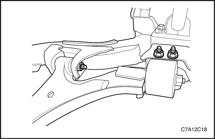
- Install the cradle to transmission rear mount bolts.
Tighten
Tighten the cradle to transmission rear mount bolts to 110 N•m (81 lb-ft).
- Install the transmission front mount and install the cradle to transmission front mount bolt.
Tighten
Tighten the transmission front mount to transmission bolts to 50 N•m (371 lb-ft).
Tighten the cradle to transmission front mount bolt to 110 N•m (81 lb-ft).
- Install the power steering gear to cradle bolts.
Tighten
Tighten the power steering gear to cradle bolts to 110 N•m (81 lb-ft).
- Install the stabilizer shaft link to strut nut.
Tighten
Tighten the stabilizer shaft link nut to 65 N•m (48 lb-ft).
- Install the tie rod to knuckle nut.
Tighten
Tighten the tie rod to knuckle nut to 50 N•m (371 lb-ft).
- Install the front exhaust muffler and catalystic coverter. Refer to Section 1G2/1G3, Engine Exhaust.
- Install the front control arm ball joint to knuckle nut and pin. Refer to "Front Control Arm" in this section.
- Install the dust cover to the under body of the vehicle. Refer to Section 9N, Frame and Underbody.
- Install the wheel with nuts.
Tighten
Tighten the wheel nut to 125 N•m (92 lb-ft).
Important : Tighten the nuts evenly and alternately in a cross or star pattern, in order to avoid excessive runout.
UNIT REPAIR
Front Control Arm Ball Joint
Disassembly Procedure
- Remove the lower control arm. Refer to "Front Control Arm" in this section.
- Place the control arm in a vise or suitable holding device.
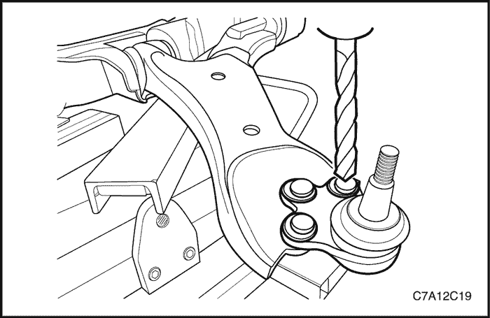
- Remove the ball joint revets using drill.
- Drill though the rivets using a 8 mm (5/16 in) drill bit.
- Enlarge the hole using a 12 mm (31/64 in) drill bit.
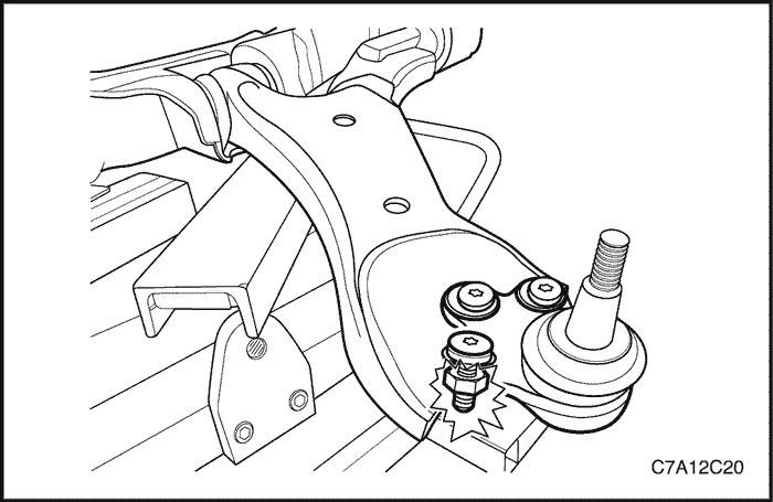
- Remove any remaining burs from the control arm.
- Remove the ball joint from the control arm. Note the position of the ball joint for reassembly.
Assembly Procedure
Important : The control arm must be clean and free of debris.
- Install the ball joint to the control arm as previously noted.
Important :
- Only use hardware provided with the new ball joint.
- The bolts must be installed with the bolt head on top of the ball joint.
- Install the ball joint to control arm bolts.
Tighten
Tighten the bolts and nuts to 68 N•m (50 lb-ft).
- Install the front control arm. Refer to "Front Control Arm" in this section.
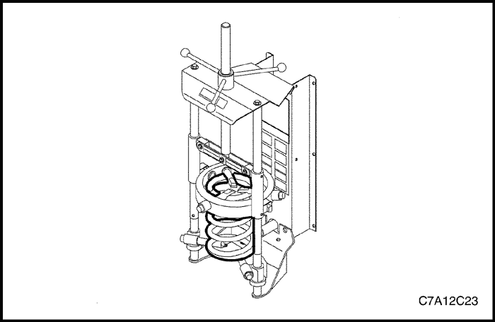
Front Strut Assembly
Tools Required
J 42991Strut Rod Nut Socket or equivalent
J 45400Strut Spring Compressor or equivalent
Disassembly Procedure
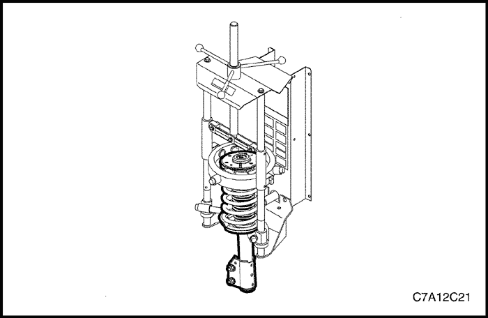
- Install the strut assembly in the J 45400using the following procedure.
- Adjust the lower legs of the J 45400to the lowest possible coil of the spring.
- Adjust the upper legs of the J 45400to the highest possible coil of the spring.
- Inspect the strut assembly to insure hooks on the strut compress legs are properly installed on the spring coils.
- Verify the strut assembly is parallel with the J 45400.
- Compress the spring enough to unload the upper strut mount.
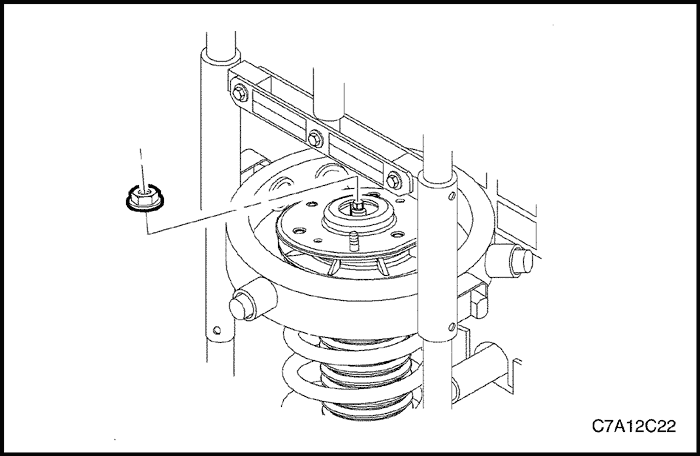
Notice : Do not allow the front strut stud to rotate during disassembly/reassembly. Use hand tools to keep the strut stud from rotating. If air tools are used, and the stud is allowed to rotate, damage to the strut may occur.
- Use the J 42991or equivalent hand tools to remove the strut shaft nut.
Important : Leave the spring in the spring compressor.
- Lower the strut from the spring assembly.
Notice : Do not handle the top mount assembly by the plastic portion. Handle the top mount assembly by the metal portion when removing/installing the top mount from/to the strut assembly. Holding the top mount assemblyby the plastic portion may loosen the snap fit of the bearing components and cause the bearing to fall apart.
- Remove the upper mount assembly, inspect for damage and deterioration. Replace as necessary.
- Remove the strut dust shield and inspect for damage and deterioration. Replace as necessary.
- Remove the hollow bumper from the strut shaft and inspect for damage and deterioration. Replace as necessary.
- Inspect the spring for damage. Replace as necessary.
Assembly Procedure
- Extend the strut to its limit of travel.
- Install the hollow bumper and dust boot to the strut shaft.
Important : The tag identifying the spring will be closer to the bottom of the spring. The end of the cold sits up against the tab on the spring seat.
- With the spring in the compressor, install the strut into the spring.
Important : The anti-rotation tab on the spring seat must face 180 degrees from the direction that the knuckle bracket points.
- Assemble the upper spring seat onto the strut shaft and align the flat with the strut to knuckle mounting bracket.
Notice : Do not handle the top mount assembly by the plastic portion. Handle the top mount assembly by the metal portion when removing/installing the top mount from/to the strut assembly. Holding the top mount assembly by the plastic portion may loosen the snap fit of the bearing components and cause the bearing to fall apart.
Important : The flat on the metal plate of the top mount assembly must face the same direction of the anti-rotation tab on the spring seat.
- Assemble the top mount onto the strut shaft and align the flat 180 degrees from flat on the upper spring seat.
- Loosely install the strut shaft nut.
Notice : Do not allow the front strut stud to rotate during disassembly/reassembly. Use hand tools to keep the strut stud from rotating. If air tools are used, and the stud is allowed to rotate, damage to the strut may occur.
- Hold the strut shaft and use the J 42991or equivalent hand tools to tighten the shaft while verifying that the upper spring seat flats align with the top mount.
Tighten
Tighten the strut shaft nut to 75 N•m (55 lb-ft).
- Release the tension on the J 45400.
- Remove the strut assembly from the J 45400.
GENERAL DESCRIPTION AND SYSTEM OPERATION
Front Suspension
The front suspension has 2 primary purposes:
- Isolate the driver from irregularities in the road surface.
- Define the ride and handling characteristics of the vehicle.
The front suspension absorbs the impact of the tires travelling over irregular road surfaces and dissipates this energy throughout the suspension system. This process isolates the vehicle occupants from the road surface. The rate at which the suspension dissipates the energy and the amount of energy that is absorbed is how the suspension defines the vehicles ride characteristics. Ride characteristics are designed into the suspension system and are not adjustable. The ride characteristics are mentioned in this description in order to aid in the understanding of the functions of the suspension system. The suspension system must allow for the vertical movement of the tire and wheel assembly as the vehicle travels over irregular road surfaces while maintaining the tire’s horizontal relationship to the road.
This requires that the steering knuckle be suspended between a lower control arm and a strut assembly. The lower control arm attaches from the steering knuckle at the outermost point of the control arm. The attachment is through a ball and socket type joint. The innermost end of the control arm attached at 2 points to the vehicle frame through semi-rigid bushings. The upper portion of the steering knuckle is attached to a strut assembly. The strut assembly then connects to the vehicle body by way of an upper bearing. The steering knuckle is allowed to travel up and down independent of the vehicle body structure and frame.
This up and down motion of the steering knuckle as the vehicle travels over bumps is absorbed predominantly by the coil spring. This spring is retained under tension over the strut assembly. A strut is used in conjunction with this system in order to dampen out the oscillations of the coil spring. A strut is a basic hydraulic cylinder. The strut is filled with oil and has a moveable shaft that connects to a piston inside the strut. Valves inside the shock absorber offer resistance to oil flow and consequently inhibit rapid movement of the piston and shaft. Each end of the shock absorber is connected in such a fashion to utilize this recoil action of a spring alone. Each end of the strut is designed as the connection point of the suspension system to the vehicle and acts as the coil spring seat. This allows the strut to utilize the dampening action to reduce the recoil of a spring alone. The lower control arm is allowed to pivot at the vehicle frame in a vertical fashion. The ball joint allows the steering knuckle to maintain the perpendicular relationship to the road surface. Front suspensions systems utilize a stabilizer shaft. The stabilizer bar connects between the left and right strut assemblies through the stabilizer link and stabilizer shaft insulators. This bar controls the amount of independent movement of the suspension when the vehicle turns. Limiting the independent movement defines the vehicles handling characteristics on turns.
Cradle
The Front Cradle is a full perimeter frame assembly with four corner-isolated attachments to the body, so that it provides vehicle occupants isolation from road inputs and powertrain noise and vibration (in conjunction with various mounts).
The Front Cradle locates and supports the weight of powertrain on a4-point mount system, front suspension components and steering components, so that they may package, assemble and function properly.
The Front Cradle also contributes to overall vehicle/front bay/rear bay structural stiffness and strength, acts as a structural element in crash as well as manage energy and minimize energy transfer into body structure in barrier impacts.