SECTION 3A
AUTOMATIC TRANSAXLE DRIVE AXLE
SPECIFICATIONS
Fastener Tightening Specifications
|
Application
|
N•m
|
Lb-Ft
|
Lb-In
|
|
Axle Shaft Caulking Nut
|
300
|
221
|
-
|
|
Lower Ball Joint Nut
|
50
|
37
|
-
|
|
Tie Rod Nut
|
45
|
33
|
-
|
|
Wheel Nuts
|
120
|
88
|
-
|
SPECIAL TOOLS
Special Tools Table
 
|
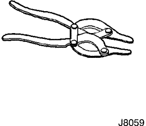
J-8059
Snap Ring Pliers
|
|
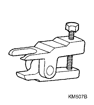
KM-507-B
Ball Joint Remover
|
|
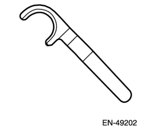
EN-49202
Drive Axleshaft Remover
|
|
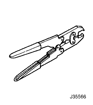
J-35566
Seal Clamp Pliers
|
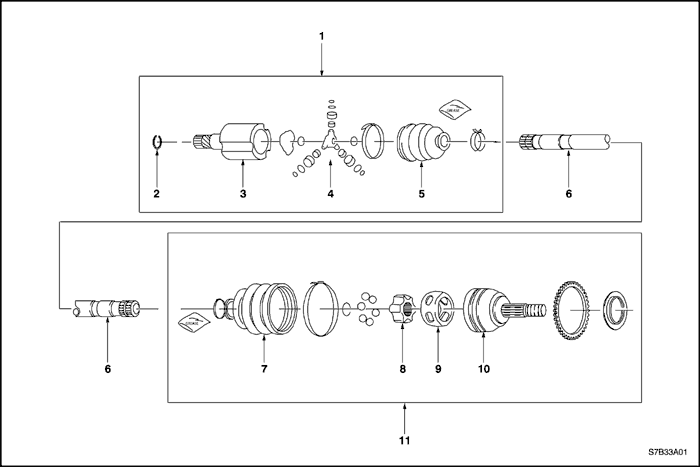
COMPONENT LOCATOR
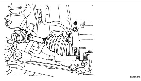
Front Drive Axle
- T/P Joint Assembly
- Snap Ring
- Tripod Housing
- Tripod Assembly
- Inboard Seal
- Axle Shaft
- Outboard Seal
- Cage
- Inner Race
- Outer Race
- C/V Joint Assembly
MAINTENANCE AND REPAIR
ON-VEHICLE SERVICE
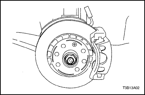
Drive Axle Assembly
Tools Required
KM-507-B Ball Joint Separator
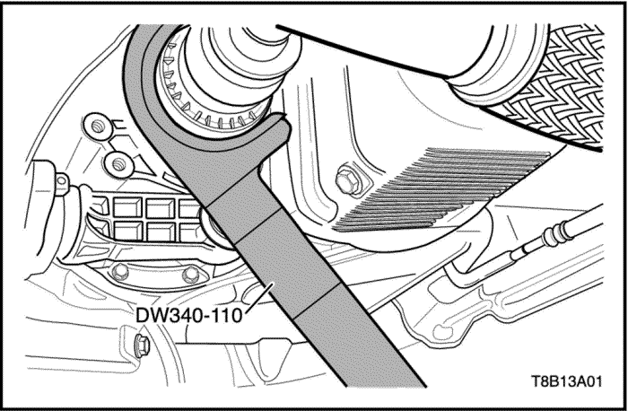
DW340-110 Axle Shaft Remover
Removal Procedure
- Raise and suitably support the vehicle.
- Remove the wheels. Refer to Section 2E, Tires and
Wheels.
- Remove the engine under covers. Refer to Section 9N, Frame and Underbody.
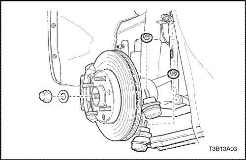
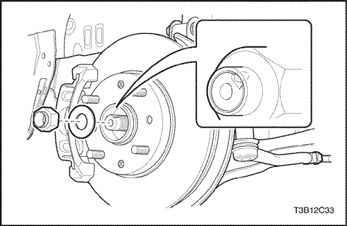
- Remove the axle shaft caulking nut. Discard the nut.
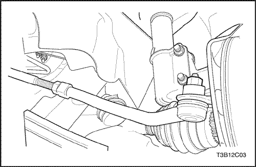
- Remove the lower ball joint nut.
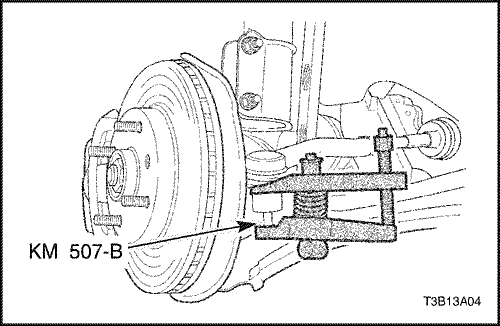
Notice : Use only the recommended tool for separating
the lower ball joint. Failure to use the recommended tool
may cause damage to the ball joint and the seal.
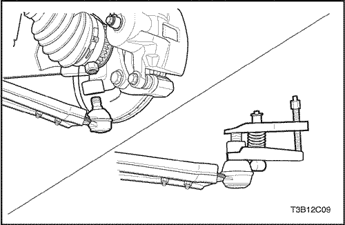
- Separate the steering knuckle from the lower ball joint
using the ball joint separator KM-507-B.
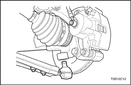
- Remove the tie rod nut.
Notice : Use only the recommended tool for separating
the tie rod from the knuckle/strut assembly. Failure to
use the recommended tool may cause damage to the
knuckle/strut assembly.
- Separate the tie rod end using the ball joint separator
KM-507-B.
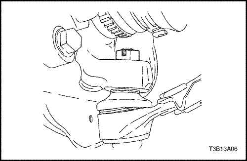
- Remove the damping block connection nut and bolt.
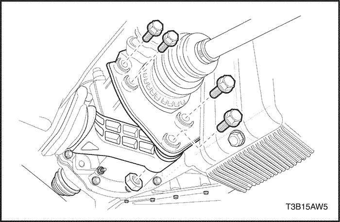
- Remove the rear mounting bracket bolts and the bracket.
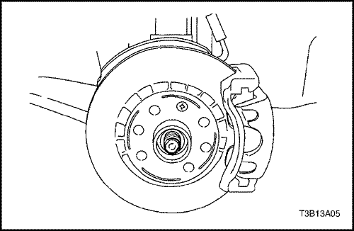
- Push the drive axle shaft from the wheel hub.
Important : Support the unfastened end of the drive
axle. Do not allow the drive axle to dangle freely from the
transaxle for any length of time after it has been removed
from the wheel hub.
Important : Place a drain pan below the transaxle to
catch the escaping fluid. Cap the transaxle drive opening
after the drive axle has been removed to keep the
fluid in and any contamination out.
- Remove the drive axle from the transaxle using the drive axle shaft remover EN-49202.
Installation Procedure
Notice : Do not damage the seals.
- Clean the hub seal and the transaxle seal.
- Install the drive axle into the transaxle.
- Install the wheel hub onto the axle shaft.
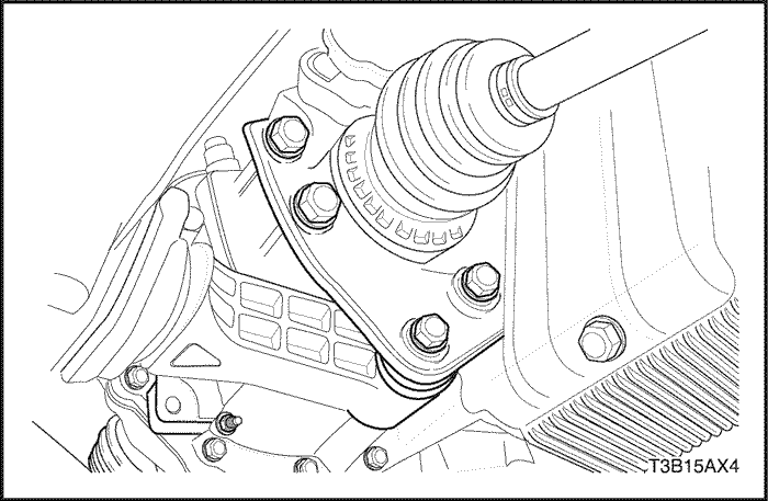
- Install the rear mounting bracket bolts and the braket.
Tighten
Tighten the rear mounting bracket bolts to 60 N•m (44 lb-ft).
- Install the damping block connection nut and bolt.
Tighten
Tighten the damping block connection nut and bolt to 80 N•m (59 lb-ft).
- Mount the steering knuckle onto the lower ball joint.
- Install the tie rod into the knuckle/strut and install the tie rod nut.
Tighten
Tighten the tie rod nut to 45 N•m (33 lb-ft).
- Install the lower ball joint nut.
Tighten
Tighten the lower ball joint nut to 50 N•m (37 lb-ft).
- Loosely install a new axle shaft caulking nut. Always
use a new nut.
- Install the wheels. Loosely install the nuts. Refer to Section 2E, Tires and Wheels.
- Lower the vehicle to the floor.
Tighten
Tighten the wheel nuts to 120 N•m (88 lb-ft).
- Tighten the axle shaft caulking nut to 300 N•m (221 lb-ft).
- Peen the caulking nut with a punch and a hammer
until the nut is locked into place on the axle shaft
hub.
- Install the engine under covers. Refer to Section 9N,
Frame and Underbody.
- Refill the transaxle fluid to the proper level. Refer to Section 5A, AISIN Automatic Transaxle.
UNIT REPAIR
Outer Joint Seal
Tools Required
J-8059 Snap Ring Pliers
J-35566 Seal Clamp Pliers
Removal Procedure
- Remove the drive axle from the vehicle. Refer to "Drive Axle Assembly"
in this section.
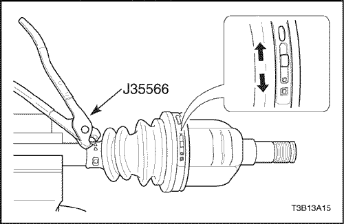
- Remove the large seal retaining clamp. Discard the
clamp.
- Remove the small seal retaining clamp. Discard the
clamp.
- Degrease the joint.
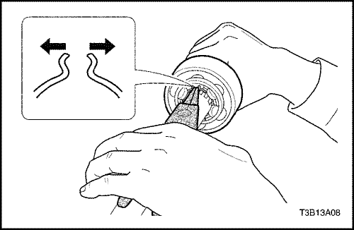
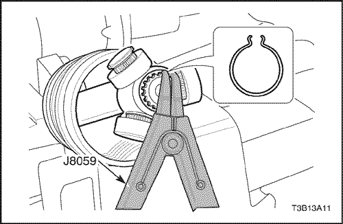
- Spread the snap ring using the snap ring pliers J-8059 and remove the outer joint the axle shaft.
Caution :
Do not disassemble the outer joint assembly. Parts are match fit and cannot be serviced separately. Improper reassembly will adversely affect both performance and safety.
- Remove the seal from the joint assembly.
Installation Procedure
- Install the seal onto the axle shaft.
- Spread the snap ring using the snap ring pliers J-8059 and remove the outer joint the axle shaft.
- Fill the joint seal with 110 to 130 g (3.9 to 4.6 ounces) of
the recommended grease. Repack the joint with 110 to
130 g (3.9 to 4.6 ounces) of the recommended grease.
- Install a new large seal retaining clamp and a new
small seal retaining clamp.
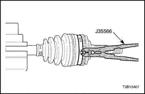
- Crimp the new small seal retaining clamp and the
new large seal retaining clamp using the seal clamp
pliers J-35566.
- Install the drive axle shaft to the vehicle. Refer to "Drive Axle Assembly"in this section.
Inner Tripod Seal
Tools Required
J-35566 Snap Ring Pliers
J-8059 Snap Ring Pliers
Removal Procedure
- Remove the drive axle from the vehicle. Refer to "Drive Axle"
in this section.
- Remove the large seal retaining clamp. Discard the clamp.
- Remove the small seal retaining clamp. Discard the clamp.
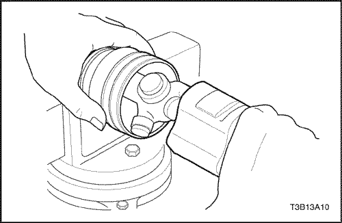
- Separate the joint housing from the boot.
- Degrease the tripod assembly.
- Remove the shaft retaining ring using the snap ring pliers J-8059.
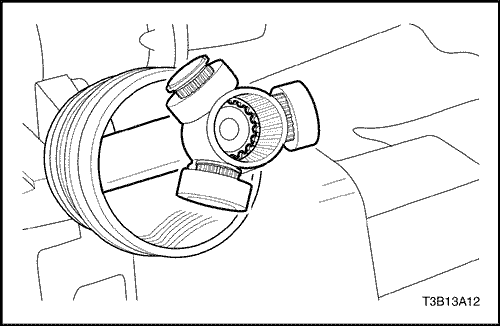
- Remove the tripod and the tripod joint retaining ring from the axle shaft.
- Remove the tripod joint seal from the axle shaft.
Installation Procedure
Tools Required
J-8059 Snap Ring Pliers
J-35566 Seal Clamp Pliers
- Install a new small seal retaining clamp onto the seal.
- Install the seal onto the axle shaft.
- Install the shaft retaining ring onto the axle shaft using
the snap ring pliers J-8059.
- Fill the tripod housing with 195 to 215 g (6.9 to 7.6
ounces) of the recommended grease. Repack the tripod
with 195 to 215 g (6.9 to 7.6 ounces) of the recommended
grease.
- Install the boot to the joint housing.
- Install a new large seal retaining clamp. Crimp the large seal retaining clamp using the seal clamp pliers J-35566.
- Crimp the new small seal retaining clamp using the
seal clamp pliers J-35566.
- Install the drive axle shaft to the vehicle. Refer to
"Drive Axle Assembly"
in this section.
GENERAL DESCRIPTION AND SYSTEM OPERATION
Front Drive Axle
General Description
Drive axles are flexible shaft assemblies that transmit
rotational force from the transaxle to the front-wheel assemblies.
Each axle assembly consists of an inner and
an outer constant-velocity joint connected to an axle
shaft. The inner joint is completely flexible and has the
ability to move in and out. The outer joint is also flexible,
but it cannot move in and out.
The drive axles use one type of outboard joint and one
type of inboard joint. The inboard ends of both drive
axles incorporate a female spline that installs over a
stub shaft protruding from the transaxle.