SECTION 4D
FRONT DISC BRAKES
SPECIFICATIONS
General Specifcations
|
Application
|
Millimeters
|
Inches
|
|
Brake Rotors:
|
.
|
.
|
|
Discard Thickness
|
18.00
|
0.71
|
|
Lateral Runout (Installed)
|
0.06
|
0.002
|
|
Rotor Diameter
|
236.00 (256*)
|
9.29 (10.08*)
|
|
Rotor Thickness (New)
|
20.00 (24*)
|
0.79 (0.94*)
|
|
Thickness Variation
|
0.1
|
0.004
|
|
Caliper
|
.
|
.
|
|
Piston Minimun Diameter
|
52 (54*)
|
2.05 (2.12*)
|
|
Wheel Cylinder Diameter:
|
.
|
.
|
|
Front
|
52 (54*)
|
2.05 (2.12*)
|
* : Optional (High Altitude)
Fastener Tightening Specirications
|
Application
|
N•m
|
Lb-Ft
|
Lb-In
|
|
Brake Hose Inlet Fitting-to-Caliper Bolt
|
40
|
30
|
-
|
|
Caliper Bleeder Valve
|
6
|
-
|
53
|
|
Caliper-to-Steering Knuckle Mounting Bolts
|
95
|
70
|
-
|
|
Retaining Frame-to-Caliper Housing Bolts
|
27
|
20
|
-
|
|
Rotor-to-Front Wheel Hub Detent Screw
|
4
|
-
|
35
|
|
Splash Shield-to-Steering Knuckle Screws
|
4
|
-
|
35
|
DIAGNOSIS
Lining Inspection
- Raise and suitably support the vehicle.
- Remove the front wheels. Refer to Section 2E, Tires and Wheels.
- Visually check the linings for minimum thickness and
wear.
- Measure the thickness.
Important : The minimum thickness of the inner or the
outer pad is 7 mm (0.28 inch).
- Install the brake pads in axle sets only.
- Install the brake pads in axle sets only.
- Install the front wheels. Refer to Section 2E, Tires and Wheels.
- Lower the vehicle.
Rotor Inspection
Thickness variation can be checked by measuring the
thickness of the rotor at four or more points around the
circumference of the rotor. All measurements must be
made at the same distance in from the edge of the rotor.
Thickness variation can be checked by measuring the thickness of the rotor at four or more points around the circumference of the rotor. All measurements must be made at the same distance from the edge of the rotor. A rotor that varies by more than 0.1 mm (0.004 inch) can cause pedal pulsation and/or front end vibration during braking. Thickness can be measured with a commercial-ly available micrometer.
A rotor that varies by more than 0.1 mm (0.004 inch) can cause pedal pulsations and/or front end vibration during brake applications. A rotor that does not meet these specifications should be refinished to specifications or replaced.
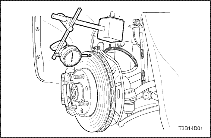
Lateral runout cannot exceed 0.06 mm (0.002 inch). If lateral runout exceeds the specification, make sure that there is no dirt between the rotor and the hub and that hub-to-rotor contact surfaces are smooth and free from burrs. Use a commercially available dial indicator to check the lateral runout according to the following procedure:
During manufacturing, the brake rotor and the tolerances
of the braking surface regarding flatness, thickness
variation, and lateral runout are held very close.
The maintenance of close tolerances on the shape of
the braking surfaces is necessary to prevent brake
roughness.
In addition to these tolerances, the surface finish must
be held to a specified range. The control of the braking
surface finish is necessary to avoid pulls and erratic performance
and to extend lining life.
Light scoring of the rotor surfaces not exceeding
0.40 mm (0.016 inch) in depth, which may result from
normal use, is not detrimental to brake operation.
Using a commercially available dial indicator, check lateral
runout as follows:
Notice : Permissible lateral runout is a maximum 0.06 mm 0.002 inch). If lateral runout exceeds the specification, make sure there is no dirt between the rotor and the hub and that contact surfaces are smooth and free from burrs.
- Position the transaxle in NEUTRAL.
- Remove the rotor. Refer to "Rotor"
in this section.
- Fasten the brake rotor to the wheel hub with two
wheel bolts.
- Fasten a dial indicator to the brake caliper.
- Set the gauge probe tip to approximately 10 mm
(0.39 inch) from the outer edge of the brake rotor,
perpendicular to the disc and under slight preload.
- Remove the dial indicator and connecting wheel bolts
to the hub.
Important : Since accurate control of the rotor tolerances
is necessary for proper performance of the disc
brakes, refinishing of the rotor should be done only with
precision equipment.
- Refinish the rotor, if required, with precision equipment.
- Refinish the rotor, if required, with precision equipment.
- Install the rotor. Refer to "Rotor"
in this section.


MAINTENANCE AND REPAIR
ON-VEHICLE SERVICE
Shoe and Lining
Removal Procedure
- Raise and suitably support the vehicle.
- To pressure wheel balance, mark the relative positions
of the wheel and the hub, and remove the front
wheel. Refer to Section 2E, Tires and Wheels.
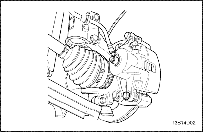
- Remove the lower bolt of the caliper assembly retaining
frame.
Important : It is not necessary to remove the caliper to
service the brake shoes.
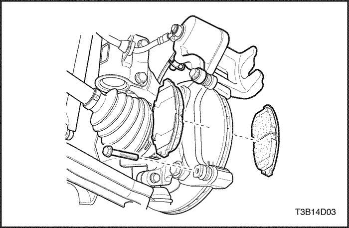
- Pull the caliper piston housing up.
- Remove the brake pads.
Installation Procedure
- Measure the minimum lining thickness. Refer to "Lining Inspection"
in this section.
- Install the brake pads into the caliper.
- Push the piston inward, if necessary.
Notice : Take care not to damage the piston seal when
the piston housing is pulled down.
- Pull down the caliper piston housing and secure it to
the retaining frame with the lower bolt.
Tighten
Tighten the retaining frame-to-caliper housing bolts to
27 N•m (20 lb-ft).
- Align the marks that were made before the wheel removal
and install the front wheels. Refer to Section 2E, Tires and Wheels.
- Lower the vehicle.
Caliper Assembly
Removal Procedure
- Raise and suitably support the vehicle.
- Mark the position of the front wheels relative to the
wheel hubs and remove the wheels. Refer to Section 2E, Tires and Wheels.
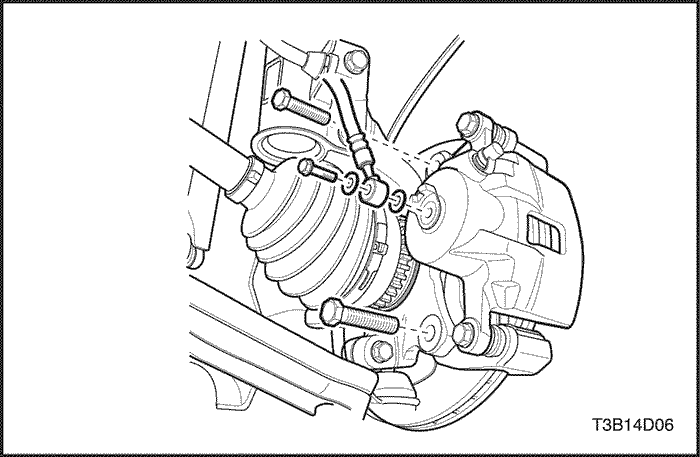
- Remove the bolt and the washers that attach the
brake hose to the caliper.
- Disconnect the brake hose, and plug the openings in
the caliper and the brake hose to prevent fluid loss
and contamination.
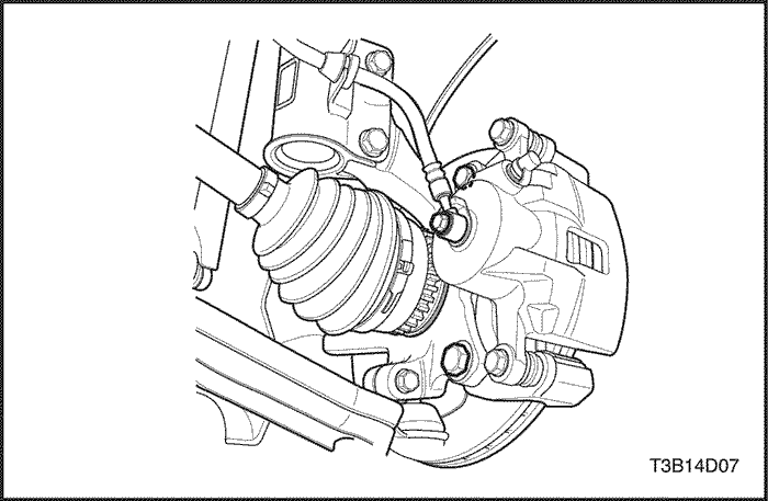
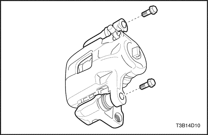
- Remove the caliper mounting bolts from the steering
knuckle, and remove the caliper assembly.
Installation Procedure
- Install the caliper assembly with the mounting bolts.
Tighten
Tighten the caliper-to-steering knuckle mounting bolts
to 95 N•m(70 lb-ft).
- Connect the brake hose.
Tighten
Tighten the brake hose inlet fitting-to-caliper bolt and
washers to 40 N•m (30 lb-ft).
- Install the front wheels. Refer to Section 2E, Tires and Wheels.
- Lower the vehicle.
- Fill the master cylinder to the proper level with clean
brake fluid.
- Bleed the caliper. Refer to Section 4A, Hydraulic Brakes
or Section 4F, Antilock Brakes,
if applicable.
- Recheck the fluid level.
Notice : Do not move the vehicle until a firm pedal is obtained,
or improper braking action will result.
- Repeatedly press the brake pedal to bring the pads in
contact with the rotor.,
Rotor
Removal Procedure
Notice : Do not hang the caliper assembly from the
brake hose. Any resulting internal hose restriction will
impede uniform braking action.
Important : To guarantee uniform braking on both sides,
both rotors must have identical surfaces regarding
smoothness and scoring depth. For this reason, always
replace both rotors.
- Remove the caliper assembly without disconnecting
the brake hoses. Refer to "Caliper Assembly"
in this
section.
- Remove the caliper bracket.
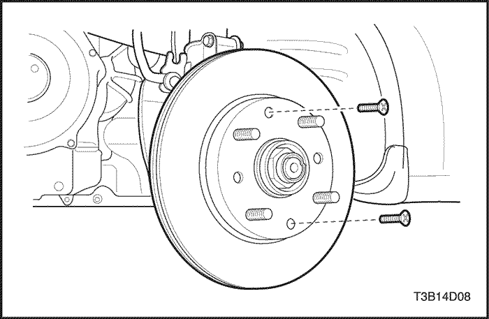
- Remove the rotor-to-front wheel hub detent screw
from the rotor and the front wheel hub.
- Pull off the rotor.
Installation Procedure
- Inspect the rotor. Refer to "Rotor Inspection"
in this
section.
- Install the rotor to the front wheel hub by tightening
the detent screw.
Tighten
Tighten the rotor-to-front wheel hub detent screw to
4 N•m (35 lb-in).
- Install the caliper bracket.
Tighten
Tighten the caliper bracket mounting bolts to 95 N•m
(70 lb-ft).
- Install the caliper assembly. Refer to "Caliper Assembly"
in this
section.
Splash Shield
Removal Procedure
- Remove the rotor. Refer to "Rotor"
in this
section.
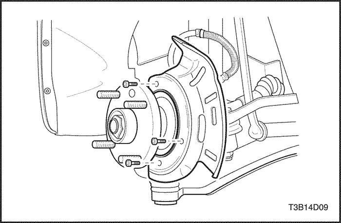
- Remove the screws for the splash shield from the
steering knuckle.
- Remove the splash shield.
Installation Procedure
- Install the splash shield.
- Secure the splash shield to the steering knuckle with
the screws.
Tighten
Tighten the splash shield-to-steering knuckle screws
to 4 N•m (35 lb-in).
- Install the rotor. Refer to "Rotor"
in this
section.
UNIT REPAIR
Caliper Overhaul
Disassembly Procedure
- Remove the caliper assembly. Refer to "Caliper Assembly"
in this
section.
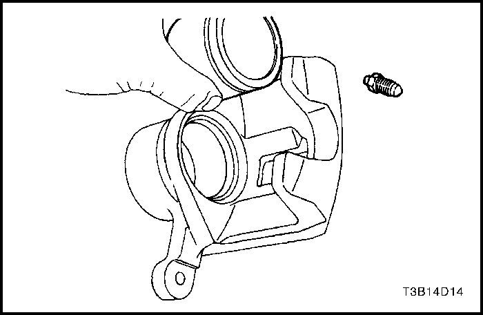
- Remove the caliper guide pin that connects the caliper
piston housing to the retaining frame.
- Remove the bleeder valve protector and the bleeder
valve.
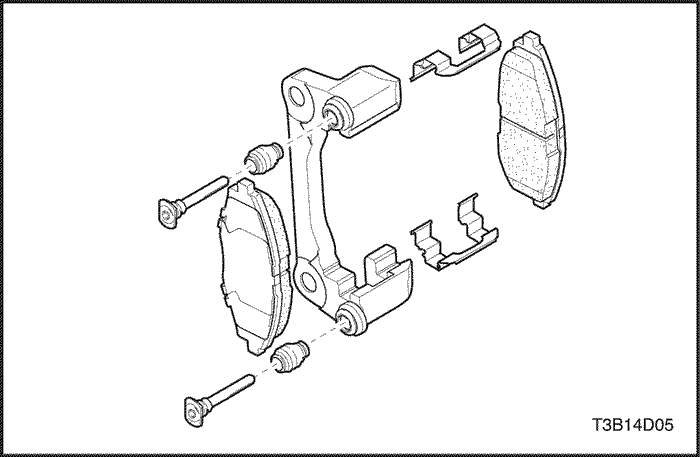
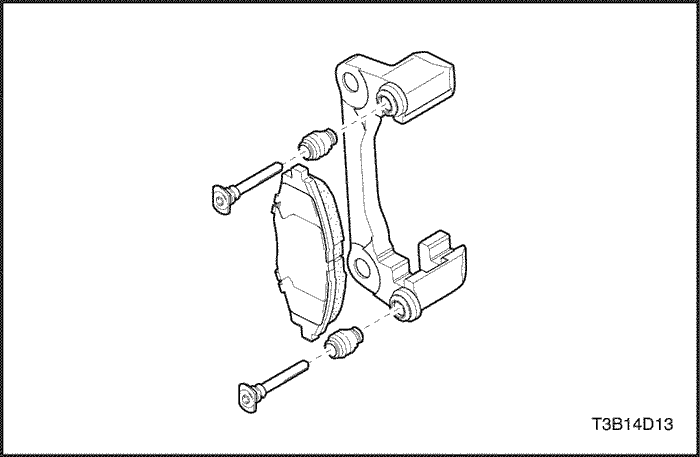
- Pull out the pins and the rubber boots.
- Remove the front pad brake set, including the pad
springs, from the caliper. Refer to "Shoe and Lining"
in this section.
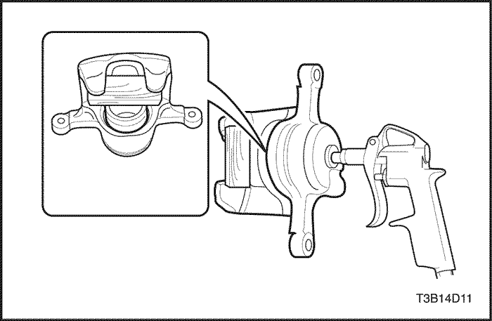
Caution :
Do not attempt to catch the piston when
removing the piston with compressed air. The piston
will pop out of its bore with enough force to
damage a hand or finger.
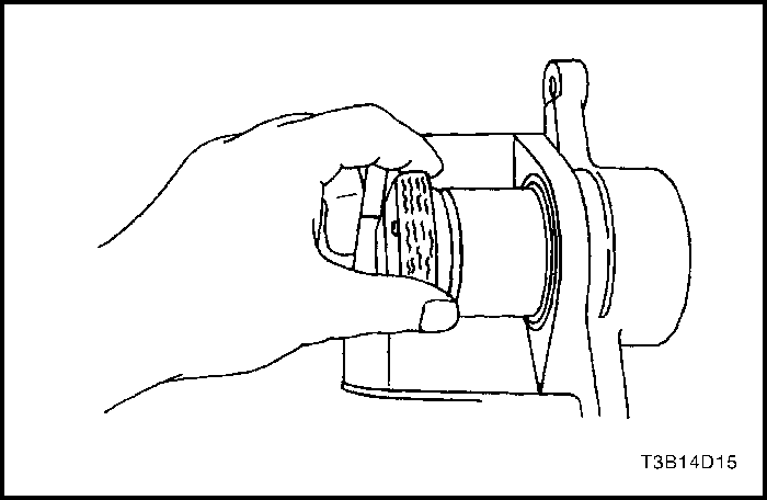
Important : Insert a piece of hardwood into the caliper
housing interior when removing the piston.
- Using compressed air, blow out the piston from the
housing.
- Remove the outer seal.
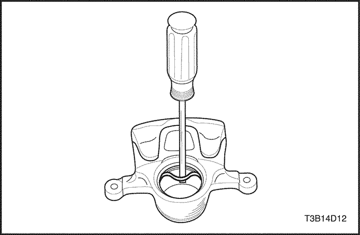
- Remove the inner seal from the caliper piston bore.
Assembly Procedure
- Clean all parts in denatured alcohol or brake fluid. Dry
the parts with unlubricated compressed air and blow
out all passages in the housing and the bleeder valve.
- Inspect the piston and the caliper for scoring, nicks,
and corrosion. Replace components if these elements
are found.
- Inspect the caliper bleeder valve.
Important : Do not use a hone or any other procedure to
remove material from the piston or the caliper bore.
- Lubricate a new piston inner seal for smooth and correct settlement.
- Install the piston inner seal into the caliper housing
groove. Make sure the seal is not twisted.
- Install the outer piston dust seal in the groove.
- Lubricate the piston with brake fluid.
- Push the piston into its bore and make sure the dust
seal is seated in the piston groove.
- Coat the pins with rubber grease and install the boots.
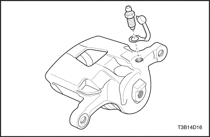
- Install the caliper bleeder valve and the dust cap.
Tighten
Tighten the caliper bleeder valve to 6 N•m (53 lb-in).
- Connect the brake pads and the pad springs.
Important : Make sure the pad springs are properly
installed.
- Connect the retaining frame to the caliper housing
with the guide pin bolts.
Tighten
Tighten the retaining frame-to-caliper housing bolts to
27 N•m (20 lb-ft).
- Install the caliper assembly. Refer to "Caliper Assembly"
in this
section.
- Bleed the brake system. Refer to Section 4A, Hydraulic Brakes
(or Section 4F, Antilock Brakes,
if applicable.)
- Repeatedly apply the brakes until a firm pedal obtained.
GENERAL DESCRIPTION
AND SYSTEM OPERATION
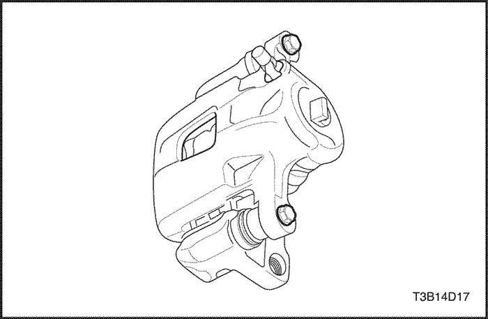
Disc Brake Caliper Assembly
This caliper has a single bore and is mounted to the
steering knuckle with two mounting bolts. Hydraulic
pressure, created by applying the brake pedal, is converted
by the caliper to a stopping force. This force acts
equally against the piston and the bottom of the caliper
bore to move the piston outward and to slide the caliper
inward, resulting in a clamping action on the rotor. This
clamping action forces the linings against the rotor,
creating friction to stop the vehicle.
Important :
- Replace all components included in the repair kits
used to service this caliper.
- Lubricate the rubber parts with clean brake fluid to
ease assembly.
- Do not use lubricated shop air on brake parts, as
damage to the rubber components may result.
- If any hydraulic component is removed or disconnected,
it may be necessary to bleed all or part of the
brake system.
- Replace the pads in axle sets only.
- The torque values specified are for dry, unlubricated
fasteners.
- Perform the service operations on a clean bench, free
from all mineral oil materials.


