MAINTENANCE AND REPAIR
ON-VEHICLE SERVICE
Service Precautions
Caution : Brake fluid may irritate eyes and skin. In case of contact, take the following actions:
-
Eye contact - rinse thoroughly with water.
-
Skin contact - wash with soap and water.
-
Ingestion - consult a physician immediately.
Caution : To help avoid personal injury due to poor braking, DO NOT tap into the vehicle's brake system to operate a trailer brake system.
Notice : When fasteners are removed, always reinstall them at the same location from which they were removed. If a fastener needs to be replaced, use the correct part number fastener for that application. If the correct part number fastener is not available, a fastener of equal size and strength (or stronger) may be used. Fasteners that are not reused, and those requiring thread-locking compound will be called out. The correct torque values must be used when installing fasteners that require them. If the above procedures are not followed, parts or system damage could result.
Notice : Use only DOT-4 or equivalent hydraulic brake fluid. The use of DOT 5 (silicone) brake fluid is not recommended. Reduced brake performance or durability may result.
Notice : Avoid spilling brake fluid on any of the vehicle's painted surfaces, wiring, cables, or electrical connectors. Brake fluid will damage paint and electrical connections. If any fluid is spilled on the vehicle, flush the area with water to lessen the damage.
Computer System Service Precautions
Take care to avoid electronic brake control module (EBCM) circuit overloading. In testing for opens or shorts, do not ground or apply voltage to any circuit unless instructed to do so by the diagnostic procedure. Test circuits only with a high-impedance multimeter. Never remove or apply power to any control module with the ignition switch in the ON position. Always turn the ignition to the OFF position before removing or connecting battery cables, fuses, or connectors.
General Service Precautions
- Disconnect the EBCM connector before performing any vehicle welding work using an electric arc welder.
- Do not attempt to disassemble any component designated as nonserviceable. The hydraulic modulator and the EBCM can be separated from each other and replaced separately but cannot be serviced. They have no replaceable parts, and there is no access to the components they contain.
Bleeding System
For this procedure, refer to
Section 4A, Hydraulic Brakes.
If air enters the hydraulic modulator, or if an unfilled modulator is installed, use the brake bleeding program in the scan tool to bleed the modulator.
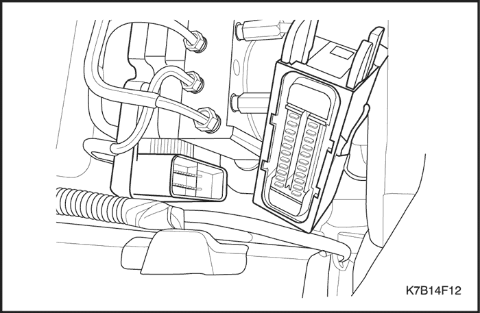


ABS Modulator Assembly
Left-Hand Drive Shown, Right-Hand Drive Similar -
Removal Procedure
- Disconnect the negative battery cable.
- Disconnect the EBCM wiring harness connector from its socket on the EBCM.
- Cover the connector and the socket with shop cloths to protect them from brake fluid.
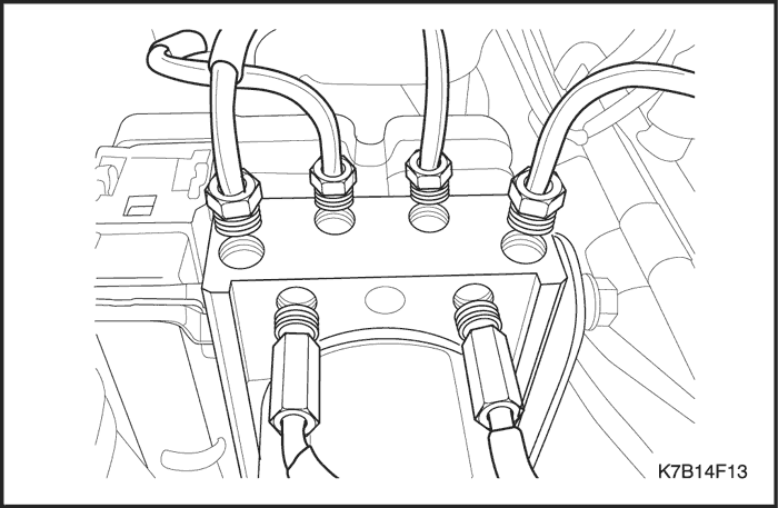
Notice : Take care not to allow air into the hydraulic unit or into the brake pipes from the master cylinder. If air gets into the hydraulic unit, it will require a bleeding procedure using a scan tool programmed for the ABS system. As long as no air enters the hydraulic unit, a simple bleeding procedure is all the system will require.
- Remove the brake pipes from the hydraulic unit. It may be necessary to loosen the brake pipe nuts on the master cylinder to allow for moving those pipes out of the way.
- Loosen the mounting nuts on the hydraulic unit.
- Move the brake pipes aside far enough to allow for lifting the ABS modulator out of the mounting bracket.
- Tighten the brake pipe nuts on the master cylinder to avoid leaking brake fluid.
- Cap the brake pipes.
Installation Procedure
- Insert the ABS modulator into its mounting bracket and install the nuts.
Tighten
Tighten the ABS modulator mounting nuts to 15 N•m (11 lb-ft).
- Remove the screw plugs and install all of the hydraulic brake pipes.
Tighten
Tighten the brake pipe nuts to 22 N•m (16 lb-ft).
- Connect the wiring harness connector.
- Connect the negative battery cable.
- Bleed the hydraulic system. Refer to Section 4A, Hydraulic Brakes.
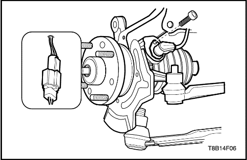
Front Wheel Speed Sensor
Removal Procedure
- Disconnect the negative battery cable.
- Raise and suitably support the vehicle.
- Remove the wheel. Refer to Section 2E, Tires and Wheels.
- Disconnect the front wheel speed sensor electrical connector.
- Remove the bolts.
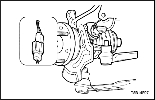
Installation Procedure
- Install the front wheel speed sensor to the steering knuckle. Secure it with the bolts.
Tighten
Tighten the front wheel speed sensor bolts to 8 N•m (71 lb-in).
- Connect the harness holder.
- Connect the electrical connector to the connector holder.
- Connect the front wheel speed sensor electrical connector.
- Install the wheel. Refer to Section 2E, Tires and Wheels.
- Lower the vehicle.
- Connect the negative battery cable.
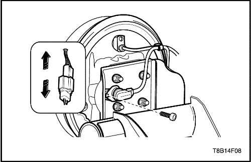
Rear Wheel Speed Sensor
Removal Procedure
- Disconnect the negative battery cable.
- Disconnect the rear wheel speed sensor electrical connector .
- Remove the rear wheel speed sensor bolt.
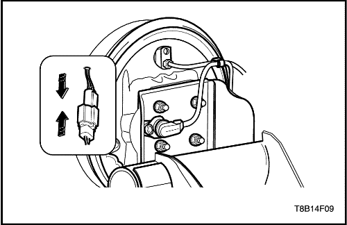
Installation Procedure
- Install the rear wheel speed sensor to the rear backing plate. Secure it with the bolt.
Tighten
Tighten the rear wheel speed sensor bolt to 8 N•m (71 lb-in).
- Connect the harness holder.
- Connect the rear wheel speed sensor electrical connector.
- Connect the negative battery cable.
| © Copyright Chevrolet Europe. All rights reserved |


