MAINTENANCE AND REPAIR
ON-VEHICLE SERVICE


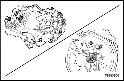
Manual Transaxle Assembly
Tools Required
Removal Procedure
- Remove the battery and battery tray. Refer to Section 1E, Engine Electrical.
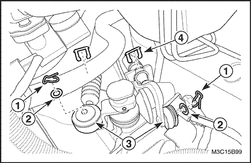
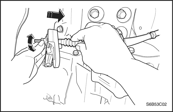
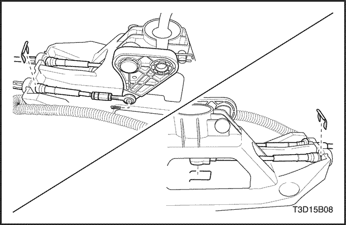
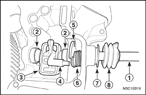
- Disconnect the select and the shift cable.
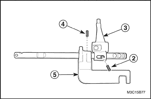
- Remove the cable pins(1).
- Remove the washers(2).
- Disconnect the select and the shift cable(3).
- Remove the cable E-rings(4).
- Disconnect the cables from the cable bracket.
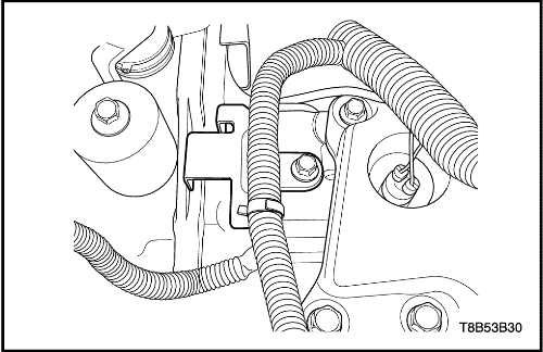
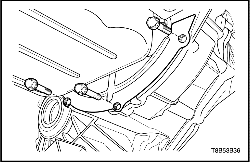
- Remove the engine wiring harness from the bracket.
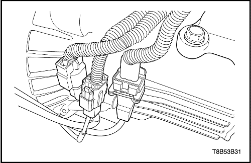
- Remove the crankshaft position sensor connector and the oxygen sensor connectors from the bracket.
- Disconnect the crankshaft position sensor connector and the oxygen sensor connectors
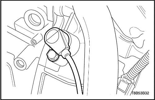
- Remove the crankshaft position sensor bolt.
- Remove the crankshaft position sensor.
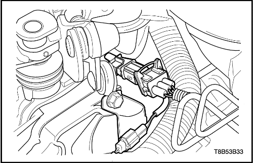
- Remove the knock sensor connector from the bracket.
- Disconnect the knock sensor connector.
- Disconnect the backup lamp switch connector.
- Remove the transaxle upper bolts.
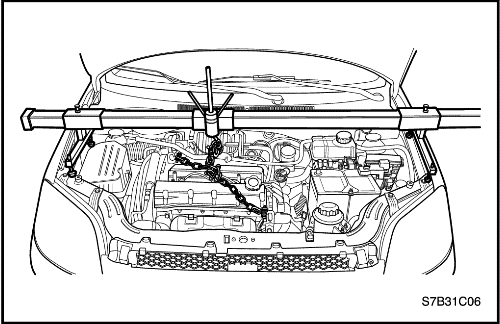
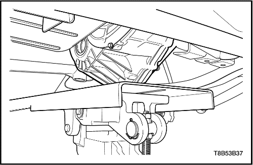
- Install the engine fixture EN-48356.
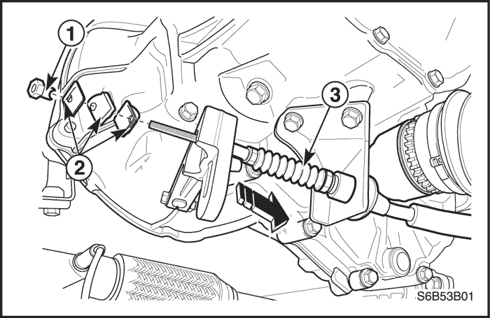
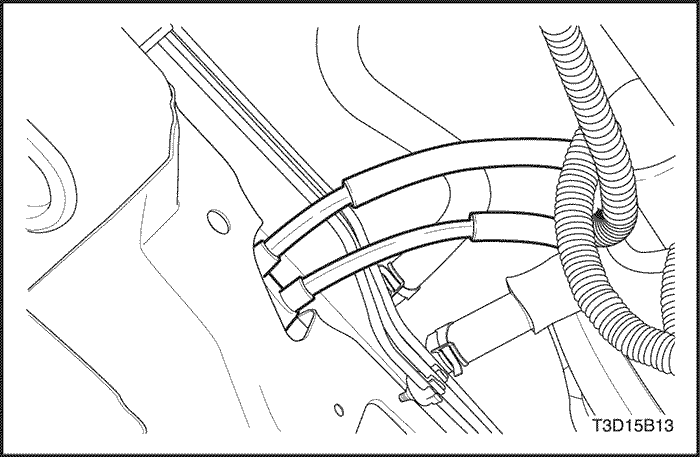
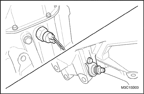
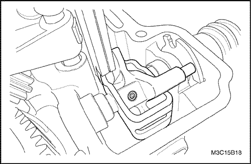
- Disconnect the clutch cable.
- Remove the cable adjust nut(1).
- Remove the front clutch release plate, the washer and the rear clutch release plate(2).
- Disconnect the cable from the transaxle mount hole(3).
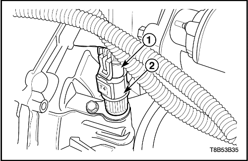
- Disconnect the vehicle speed sensor connector(1).
- Remove the vehicle speed sensor(2).
- Remove the front exhaust pipe. Refer to Section 1G, Engine Exhaust.
- Remove the catalytic converter. Refer to Section 1G, Engine Exhaust.
- Remove the drive axle. Refer to Section 3B, Manual Transaxle Drive Axle.
- Remove the starter motor. Refer to Section 1E, Engine Electrical.
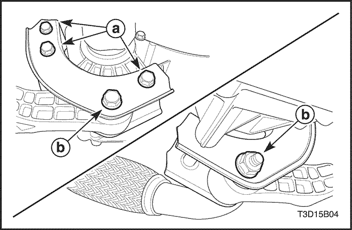
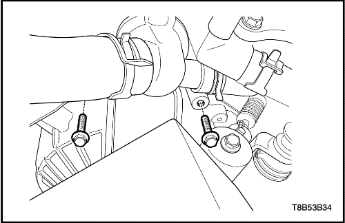
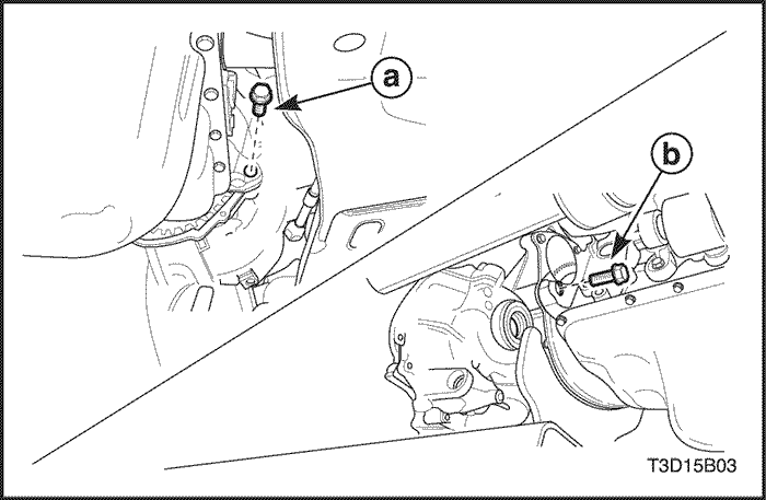
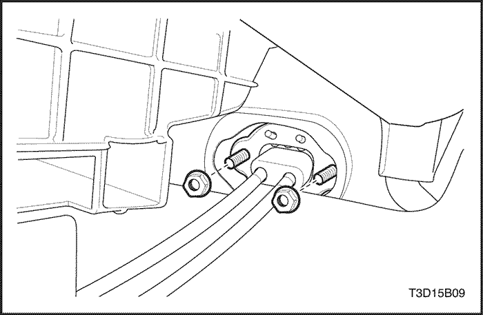
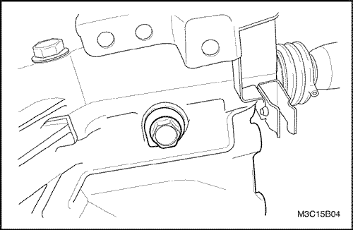
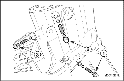
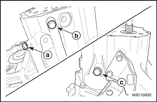
- Remove the damping block connection nut and bolt(b).
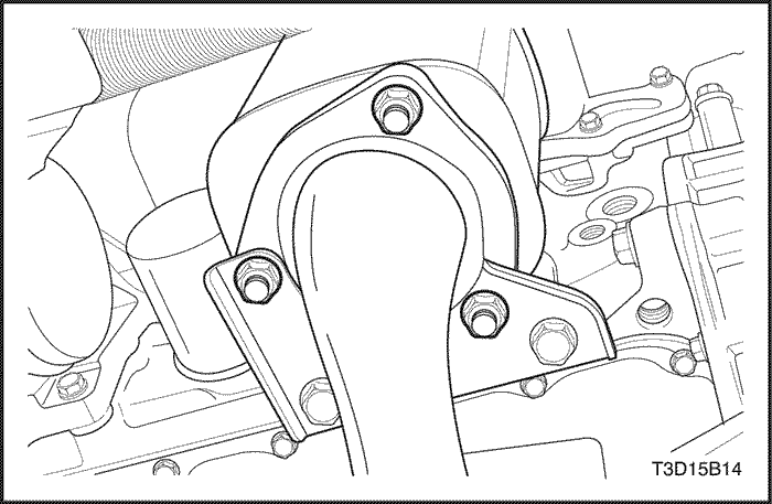
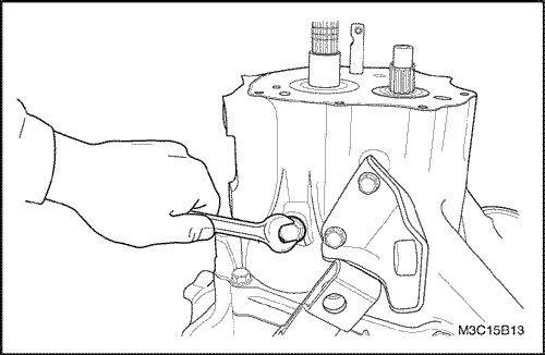
- Remove the three rear mounting bracket bolts(a).
- Remove the rear mounting bracket from the transaxle.
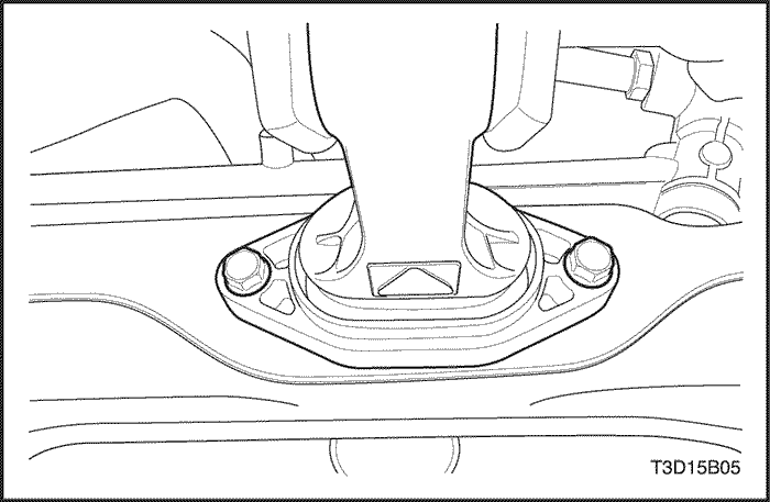
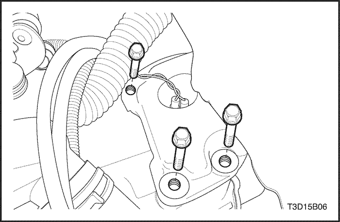
- Remove the rear damping block retaining bolts.
- Remove the rear damping block.
- Remove the clutch housing lower plate bolts.
- Remove the clutch housing lower plate.
- Support the transaxle assembly using the supporting jack.
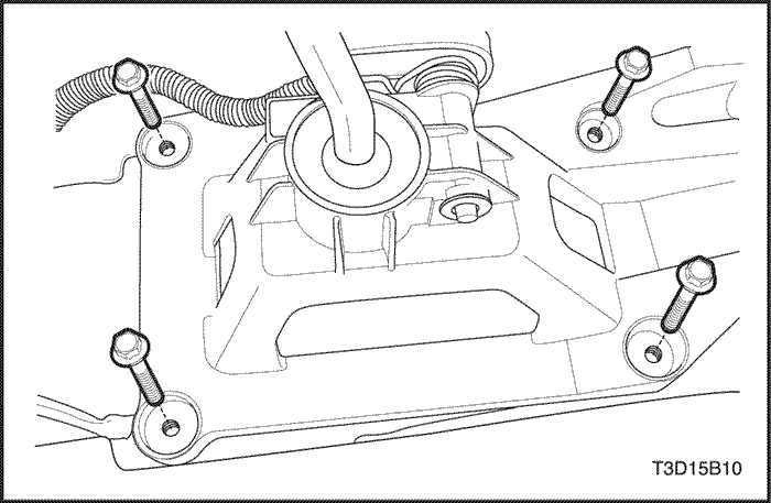
- Remove the transaxle lower bolts.
- Remove the left transaxle mounting bracket bolts.
- Carefully remove the transaxle assembly from the vehicle.
Installation Procedure
- Install the transaxle into the vehicle and support the transaxle assembly using the supporting jack.
- Install the left transaxle mounting bracket bolts.
Tighten
Tighten the left transaxle mounting bracket bolts to 55-65 N•m (41-48 lb-ft).
- Install the transaxle lower bolts.
Tighten
Tighten the bolts to 55-65 N•m (41-48 lb-ft).
- Install the clutch housing lower plate and the clutch housing lower plate bolts.
Tighten
Tighten the clutch housing lower plate bolts to 10 N•m (89 lb-in).
- Install the rear damping block and the rear damping block retaining bolts.
Tighten
Tighten the rear damping block retaining bolts to 50-60 N•m (37-44 lb-ft).
- Install the rear bracket and the rear mounting bracket bolts.
Tighten
- Tighten the rear mounting bracket bolts(a) to 55-65 N•m (41-48 lb-ft).
- Tighten the damping block connection nut and bolt(b) to 75-95 N•m (55-70 lb-ft).
- Install the starter motor. Refer to Section 1E, Engine Electrical.
- Install the drive axle. Refer to Section 3B, Manual Transaxle Drive Axle.
- Install the catalytic converter. Refer to Section 1G, Engine Exhaust.
- Install the front exhaust pipe. Refer to Section 1G, Engine Exhaust.
- Install the vehicle speed sensor(2).
- Connect the vehicle speed sensor connector(1).
- Connect the clutch cable.
- Connect the cable to the transaxle mount hole.
- Install the front clutch release plate, the washer and the rear clutch release plate.
- Install the cable adjust nut.
- Remove the engine fixture EN-48356.
- Install the transaxle upper bolts.
Tighten
Tighten the bolts to 55-65 N•m (41-48 lb-ft).
- Connect the backup lamp switch connector.
- Connect the knock sensor connector.
- Install the knock sensor connector to the bracket.
- Install the crankshaft position sensor and the crankshaft position sensor bolt.
Tighten
Tighten the crankshaft position sensor bolt to 5-8 N•m (44-71 lb-in).
- Connect the crankshaft position sensor connector and the oxygen sensor connectors.
- Install the crankshaft position sensor connector and the oxygen sensor connectors to the bracket.
- lnstall the engine wiring harness to the bracket.
- Connect the select and shift cable.
- Connect the cable from the cable bracket.
- Install the cable E-rings(4).
- Connect the select and the shift cable(3).
- Install the washers(2).
- Install the cable pins(1).
- Install the battery and battery tray. Refer to Section 1E, Engine Electrical.
- Adjust the clutch cable. Refer to Section 5C2, Clutch.
- Check the fluid level. Refer to "Checking fluid level"
in this section.
Speedometer Driven Gear
(Left-Hand Drive Shown, Right-Hand Drive Similar)
Removal Procedure
- Disconnect the vehicle speed sensor connector.
- Remove the bolt and the speedometer driven gear assembly.
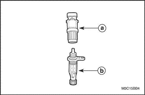
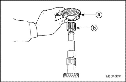
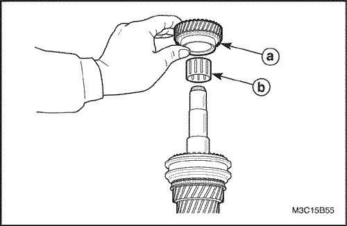
- Remove the vehicle speed sensor from the speedometer driven gear.
-
- a. Vehicle speed sensor.
- b. Speedometer driven gear.
Caution : Be careful to prevent personal injury while the exhaust pipe is hot.
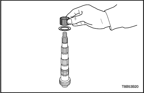
Inspection Procedure
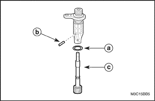
- Remove the O-ring from the speedometer driven gear housing.
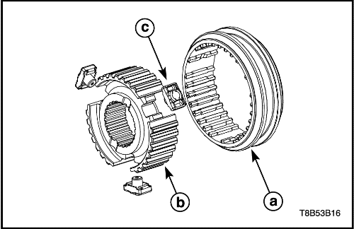
- Remove the driven gear pin and disconnect the driven gear.
- Check for a damaged or torn O-ring.
- Check for a worn or damaged tooth of driven gear.
-
- a. O-ring.
- b. Driven gear pin.
- c. Driven gear.
Installation Procedure
- Install the speedometer driven gear assembly to transaxle housing.
Tighten
Tighten the speedometer driven gear assembly bolt to 4-7 N•m (35-62 lb-in).
- Install the vehicle speed sensor.
- Connect the vehicle speed sensor connector.
Gear Shift Control Cable
Removal Procedure
- Disconnect the negative battery cable.
- Disconnect the transaxle side select and shift control cable.
- Remove the cable pins (1).
- Remove the washers (2).
- Disconnect the select and shift control cable (3).
- Remove the cable E-rings (4).
- Disconnect the cables from the cable bracket.
- Remove the floor console. Refer to Section 9G, Interior Trim.
- Remove the clip, cable pin and E-rings and disconnect the gear shift lever side select and shift control cable.
- Remove the select and shift control cable.
- Remove the nuts.
- Pull the cables out in the passenger room.
Installation Procedure
- Push the cables toward the engine compartment through dash panel's hole slightly.
- Position the cables on the select and the shift lever.
- Install the select and shift cable nut and cable grommet.
Tighten
Tighten the nuts to 4-7 N•m (35-62 lb-in).
- Connect the gear shift lever side select and shift control cable.
- Install the pin, E-rings and clip.
- Connect the select and shift cable.
- Connect the cable from the cable bracket.
- Install the cable E-rings(4).
- Connect the select and the shift cable(3).
- Install the washers(2).
- Install the cable pins(1).
- Install the floor console. Refer to Section 9G, Interior Trim.
- Connect the negative battery cable.
Gear Shift Control Lever
Removal Procedure
- Disconnect the negative battery cable.
- Remove the floor console. Refer to Section 9G, Interior Trim.
- Disconnect the select and shift control cable. Refer to "Gear Shift Control Cable"
in this section.
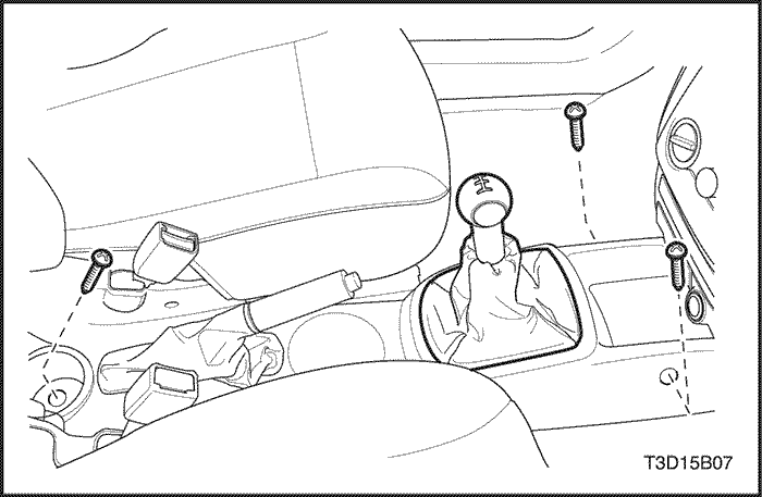
- Remove the gear shift control lever assembly.
- Remove the bolts.
- Remove the gear shift control lever assembly.
Installation Procedure
- Install the gear shift control lever assembly.
Tighten
Tighten the bolts to 5-10 N•m (44-89 lb-in).
- Connect the select and shift control cable. Refer to "Gear Shift Control Cable"
in this section.
- Install the floor console. Refer to Section 9G, Interior Trim.
- Connect the negative battery cable.
UNIT REPAIR
Gear Unit
Tools Required
DW09940-53111 Gear, Bearing Installer
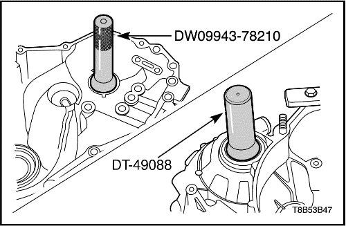
DW09943-78210 Bushing, Seal Installer
DT-49082 Needle Bearing Remover
DT-49083 Needle Bearing Installer
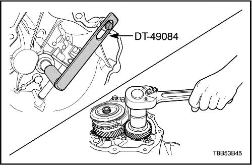
DT-49084 Input Shaft Holder
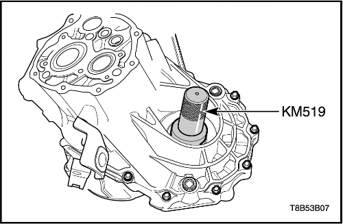
KM519 Oil Seal Installer
DT-49088 Oil Seal Installer
Disassembley Procedure
- Remove the manual transaxle. Refer to "Manual Transaxle Assembly"
in this section.
- Remove the related clutch parts. Refer to Section 5C2, Clutch (Cable Type).
- Disconnect the backup light switch and speedometer driven gear assembly.
- Remove the nut and backup light switch.
- Remove the bolt and the speedometer driven gear assembly.
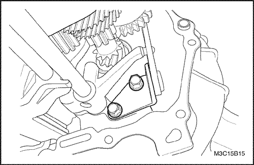
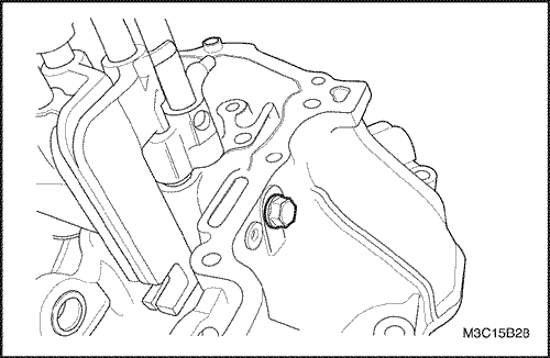
- Remove the shift interlock bolt.
Important : Certainly remove the shift interlock bolt. Otherwise, gear shift and shaft assembly can not be removed.
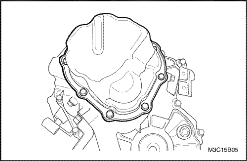
- Remove the side cover.
- Remove the bolts.
- Remove the side cover using a rubber hammer.
- Remove the sealant on the side cover and the transaxle case.
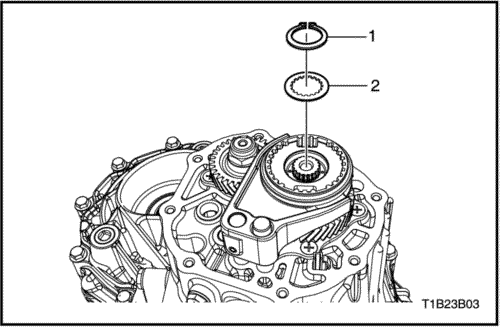
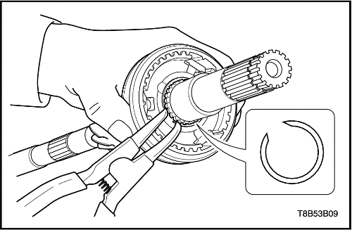
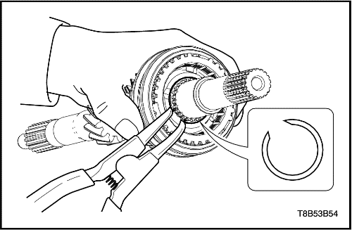
- Remove the input shaft circlip (1).
- Remove the fifth-gear synchronizer hub plate (2).
- Remove the fifth-gear shift fork pin (1) using a pin punch and a hammer.
- Pull and remove the input shaft fifth-gear fork (1) and the synchronizer hub assembly (2) together.
- Remove the synchronizer ring, levers and sleeve
from the fifth synchronizer hub assembly.
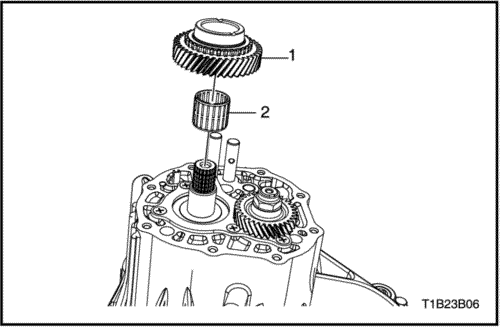
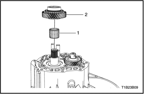
- Pull and remove the input shaft fifth-gear (1).
- Remove the input shaft fifth-gear bearing (2).
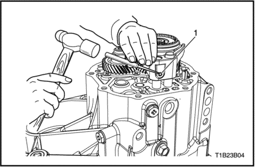
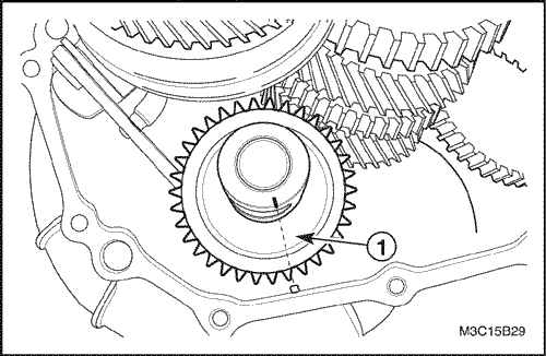
- Remove the counter shaft fifth gear nut.
- Move the shift shaft lever into the fourth gear position.
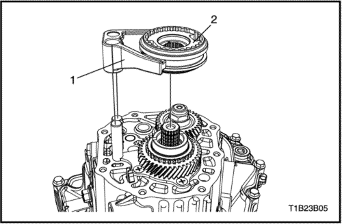
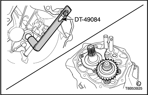
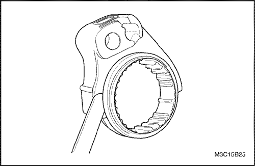
- Hold the input shaft using the input shaft holder DT-49084.
- Remove the caulked nut.
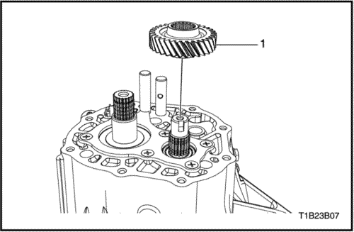
- Remove the counter shaft fifth-gear (1).
- Remove the left case plate and the counter shaft bearing shim.
- Remove the screws.
- Remove the left case plate.
- Remove the counter shaft bearing shim.
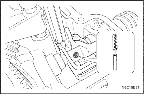
- Remove the shift shaft spring and ball.
- Remove the bolt and remove the fifth-reverse gear shift shaft spring and ball (1).
- Remove the bolt and remove the third-fourth gear shift shaft spring and ball (2).
- Remove the bolt and remove the first-second gear shift shaft spring and ball (3).
- Remove the reverse idle gear shaft bolt.
Important : The case (Left) can not be removed without removing the reverse idle gear shaft bolt.
- Remove the transaxle case (Left).
- Remove the bolts from the left side case.
- Remove the bolts from the right side case.
- Remove the left side case by hitting with a rubber hammer lightly.
- Remove the sealant on the case.
- Remove the reverse gear shift lever.
- Remove the bolts.
- Remove the reverse gear shift lever.
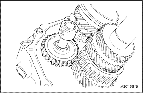
- Remove the reverse idle gear shaft assembly.
- Push the reverse idle gear toward inner case.
- Pull the shaft and remove the reverse idle gear and shaft.
- Remove the reverse idle gear from the shaft.
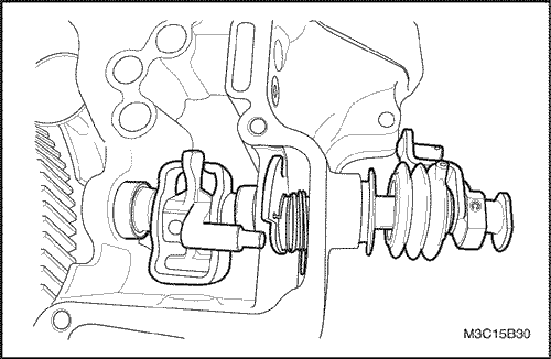
- Remove the fifth-reverse gear shift shaft.
- Remove the shift & select lever inner and outer pins.
- Remove the gear shift & select shaft assembly.
- Remove the shift and select shaft (1).
- Remove the gear select spring assembles (2).
- Remove the gear shift interlock plate (3).
- Remove the gear shift lever (4).
- Remove the fifth & reverse gear shift cam (5).
- Remove the return spring (6).
- Remove the shift and select bellows (8).
- Remove the shift and select shaft oil seal (7).
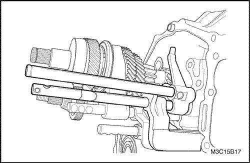
- Remove the gear unit.
- Remove the gear unit and the shift shaft assembly together.
Notice : Be careful not to damage teeth of the counter shaft pinion and the differential ring gear.
- Remove the high and the low speed shift shaft assembly from the gear unit.
- Remove the differential assembly.
- Insert a wooden stick into the lower side of differential.
- Remove the differential assembly by moving it right and left.
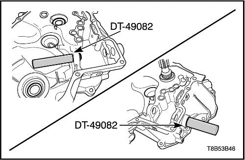
- Remove the shift and select shaft needle bearings using needle bearing remover DT-49082.
- Remove the related parts of the transaxle case (Left side).
- Remove the oil gutter.
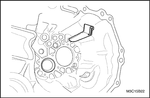
- Remove the differential left side oil seal using a hammer and a copper chisel.
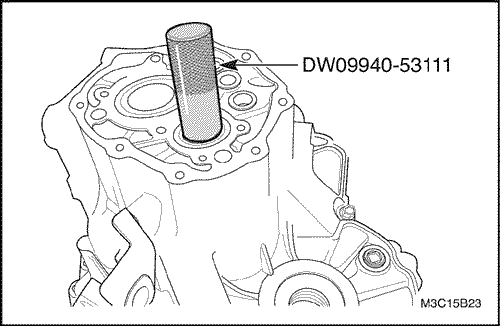
- Remove counter shaft bearing outer race using a hammer and the gear, bearing installer DW09940-53111.
- Remove the related parts of the transaxle case (Right side).
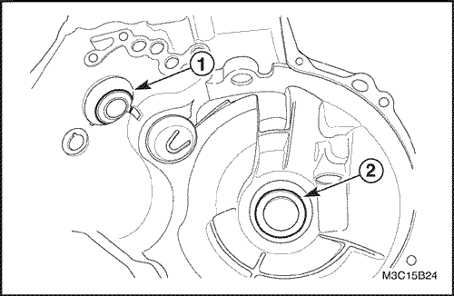
- Remove the input side oil seal using a screwdriver (1).
- Remove the differential right side oil seal using a hammer and a copper chisel (2).
Synchronizer Sleeve and Shift Fork Inspection
- Measure the clearance between synchronizer sleeve and shift fork and if the clearance exceeds the limit, replace the shift fork.
-
- Unit : mm(in.)
|
Clearance
Between
Sleeve and Shift Fork
|
Standard
|
Limit
|
|
0.2~0.6
(0.008~0.024)
|
1.0
(0.039)
|
Assembly Procedure
- Install the related parts of the transaxle case (Right Side).
- Install the input shaft oil seal using the bushing seal installer DW09943-78210.
- Install the differential right side oil seal using the oil seal installer DT-49088.
Important : Use only a new oil seal.
Important : Coat the transaxle inner parts with gear fluid when installing.
- Install the related parts of the transaxle case (Left side).
- Install the oil gutter.
- Install the differential left side oil seal using the oil seal installer KM519.
- Install the differential assembly to the right side of the transaxle case.
- Install the low and the high speed shift shaft assembly to the gear unit.
- Install the gear unit.
- Push the gear unit by matching it with the input and the count shaft hole.
Notice : Be careful not to damage teeth of the counter shaft pinion and the differential ring gear.
- Install the fifth-reverse gear shift shaft.
- Install the fifth-reverse gear shift shaft ball and spring.
Tighten
Tighten the bolt to 10-16 N•m (7-12 lb-ft).
- Install the reverse idle gear shaft assembly and the reverse gear shift lever.
- Install the reverse idle gear shaft assembly (1).
Important : Match the marking of the reverse idle gear shaft bolt hole with the protrusion of the transaxle case (Right side).
- Install the reverse gear shift lever.
Tighten
Tighten the bolts to 18-28 N•m (13-21 lb-ft).
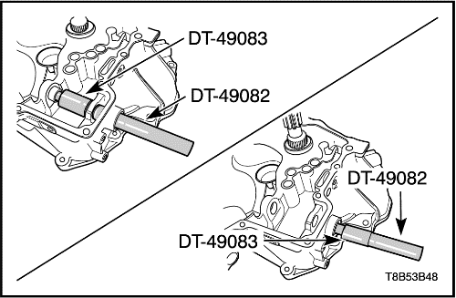
- Install the shift and select shaft needle bearings using needle bearing installer DT-49083 with needle bearing remover DT-49082.
- Install the gear shift and select shaft assembly.
- Install the shift & select shaft oil seal.
- Install the shift & select bellows.
- Install the gear select spring assembles.
- Install the gear shift interlock plate.
- Install the gear shift lever.
- Install the fifth & reverse gear shift cam.
- Install the return spring.
- Install the shift & select shaft.
- Install the shift & select lever inner and outer pins.
Important : When installing inner and outer pins, make the crevices of two pins be symmetric each other.
- Install the transaxle left side case.
- Coat the transaxle case with recommended sealant.
|
Transaxle Case Sealant
|
THREE BOND 1215 or LOCTITE 5702
|
- Install the transaxle left side case to the transaxle right side case.
Tighten
Tighten the bolts to 15-22 N•m (11-16 lb-ft).
- Install the first-second gear shift shaft ball and spring.
Tighten
Tighten the bolt to 10-16 N•m (7-12 lb-ft) (a).
- Install the third-fourth gear shift shaft ball and spring.
Tighten
Tighten the bolt to 10-16 N•m (7-12 lb-ft) (b).
- Install the reverse idle gear shaft bolt.
Tighten
Tighten the bolt to 18-28 N•m (13-21 lb-ft) (c).
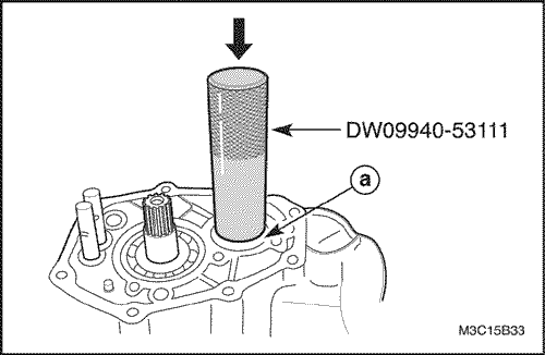
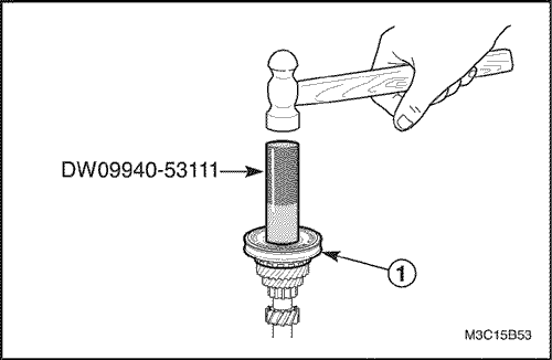
- Install the counter shaft bearing outer race.
- Install the counter shaft bearing outer race using the gear, bearing installer DW09940-53111.
-
- a. Bearing outer race.
Important : Check if the bearing and the outer race are correctly installed by rotating counter shaft.
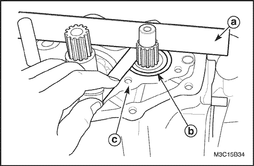
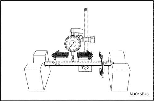
- Install the counter shaft bearing shim.
- Measure clearance between the transaxle case surface and the bearing outer race using a straight ruler and gauge.
- Select shim in order that clearance is within standard.
-
- Unit : mm (in.)
|
Measured value (A)
|
Shim thickness
|
|
0.33-0.37 (0.0130-0.0146)
|
0.55 (0.0217)
|
|
0.38-0.42 (0.0147-0.0165)
|
0.60 (0.0236)
|
|
0.43-0.47 (0.0169-0.0185)
|
0.65 (0.0256)
|
|
0.48-0.52 (0.0189-0.0205)
|
0.70 (0.0276)
|
|
0.53-0.57 (0.0209-0.0224)
|
0.75 (0.0295)
|
|
0.58-0.62 (0.0228-0.0244)
|
0.80 (0.0315)
|
|
0.63-0.67 (0.0248-0.0264)
|
0.85 (0.0335)
|
|
0.68-0.72 (0.0268-0.0283)
|
0.90 (0.0354)
|
|
0.73-0.77 (0.0287-0.0303)
|
0.95 (0.0374)
|
|
0.78-0.82 (0.0307-0.0323)
|
1.00 (0.0394)
|
|
0.83-0.87 (0.0327-0.0343)
|
1.05 (0.0413)
|
|
0.88-0.92 (0.0346-0.0362)
|
1.10 (0.0433)
|
|
0.93-0.97 (0.0366-0.0382)
|
1.15 (0.0453)
|
|
0.98-1.02 (0.0386-0.0402)
|
1.20 (0.0472)
|
|
1.03-1.07 (0.0406-0.0421)
|
1.25 (0.0492)
|
-
- a. Straight ruler
- b. Bearing outer race
- c. Case surface
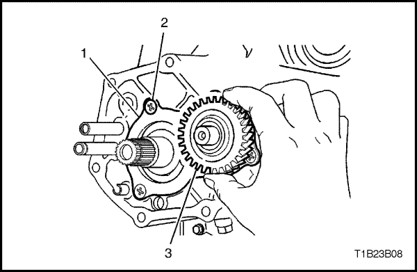
- Install the left case plate (1).
- Install the 6 new left case plate screws (2).
Tighten
Tighten the screws to 8-9 N•m (71-80 lb-in).
- Install the counter shaft fifth gear (3).
Important : Position the machined boss side toward the side cover plate.
- Insert the input shaft fifth gear bearing (1) into the input shaft.
- Install the input shaft fifth gear (2).
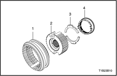
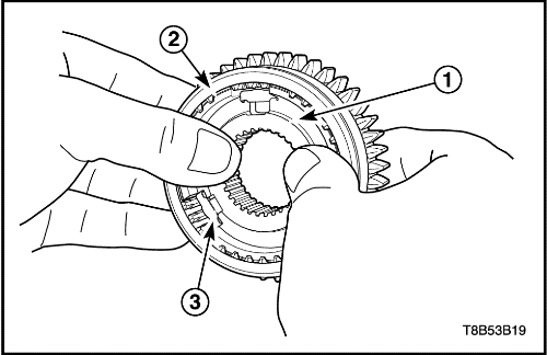
- Assemble the fifth gear synchronizer hub assembly.
- Position the longer boss side of hub (2) toward inner side.
- Position the chamfered spline of sleeve (1) toward inner side and install the hub (2) to the sleeve (1).
- Position the lever marks side toward outer side and install the levers(3) into the hub(2).
- Install the synchronizer ring (4) inserting ring lugs into the spaces between levers (3).
Important : Make sure that the lever mark must be showed after assembly.
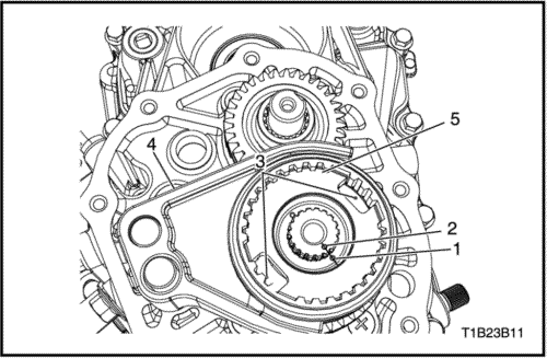
- Install the fifth gear fork to the synchronizer hub assembly.
- Install the fifth gear fork (4) and the synchronizer hub assembly (5) to the input shaft.
Important : Position the longer boss side of hub toward inner side and match the hub mark (1) with the input shaft punched mark (2). Make sure that the lever marks(3) must be showed to the fifth synchronizer hub assembly.
- Install the new fifth gear shift fork pin (1) using a pin punch and a hammer.
- Install the fifth gear synchronizer hub plate (2).
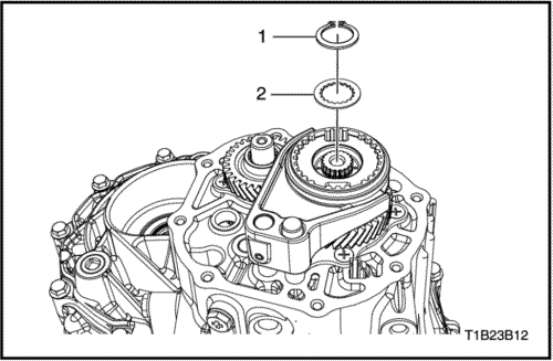
- Install the new input shaft circlip (1).
- Install the counter shaft fifth gear nut.
- Move the shift shaft lever into the fifth gear position.
- Hold the input shaft using the input shaft holder DT-49084.
Tighten
Tighten the fifth gear nut to 60-80 N•m (44-59 lb-ft).
- Caulk the nut using a chisel and a hammer.
- Install the side cover.
- Coat the side cover with recommended sealant.
|
Side Cover Sealant
|
THREE BOND 1215 or LOCTITE 5702
|
Tighten
Tighten the side cover bolts to 8-12 N•m (71-106 lb-in).
- Install the shift interlock bolt.
Tighten
Tighten the shift interlock bolt to 18-28 N•m (13-21 lb-ft).
- Install the backup light switch and the speedometer driven gear assembly.
- Install the backup light switch.
Tighten
Tighten the nut to 15-18 N•m (11-13 lb-ft).
- Install the speedometer driven gear assembly.
Tighten
Tighten the bolt to 4-7 N•m (35-62 lb-in).
- Install the related clutch parts. Refer to Section 5C2, Clutch (Cable Type).
- Install the transaxle assembly. Refer to "Manual Transaxle Assembly"
in this section.
Input Shaft
Tools Required
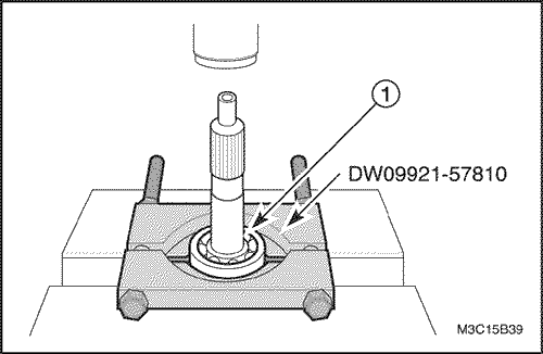
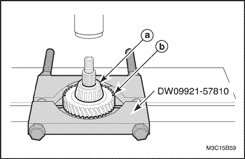
DW09921-57810 Gear, Bearing Remover
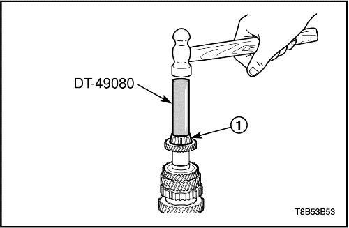
DT-49080 Gear, Bearing Installer
DW09940-53111 Gear, Bearing Installer
Disaasemly Procedure
- Remove the gear unit. Refer to "Gear Unit"
in this section.
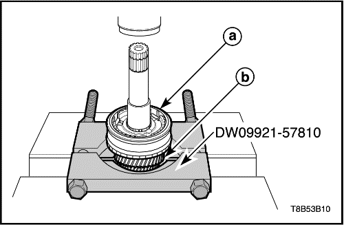
- Remove the input shaft right side bearing.
- Position the bearing to the gear, bearing remover DW09921-57810.
- Remove the bearing by pressing (1).
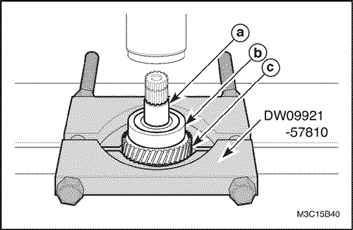
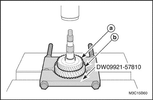
- Remove the input shaft fifth gear spacer, the left side bearing and the fourth gear.
- Position the fourth gear to the gear, bearing remover DW09921-57810.
- Remove the following parts.
-
- a. Fifth gear spacer.
- b. Left side bearing.
- c. Fourth gear
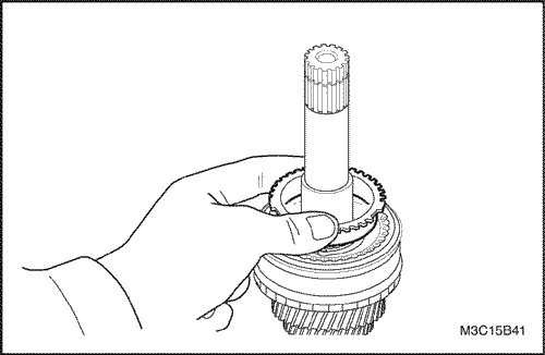
- Remove the fourth gear bearing.
- Remove the fourth gear synchronizer ring.
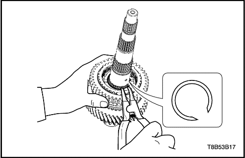
- Remove the third-fourth synchronizer circlip.
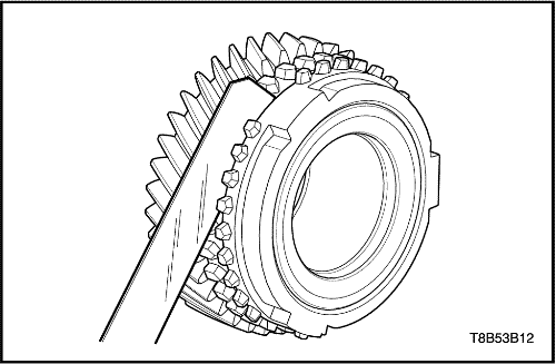
- Remove the third-fourth synchronizer hub assembly, the third gear/synchronizer ring.
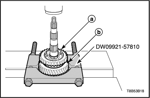
- Position the third gear to the gear, bearing remover DW09921-57810.
- Remove the following parts.
-
- a. Third-fourth synchronizer hub assembly.
- b. Third gear and synchronizer ring.
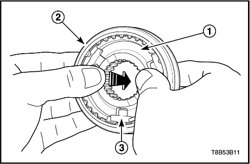
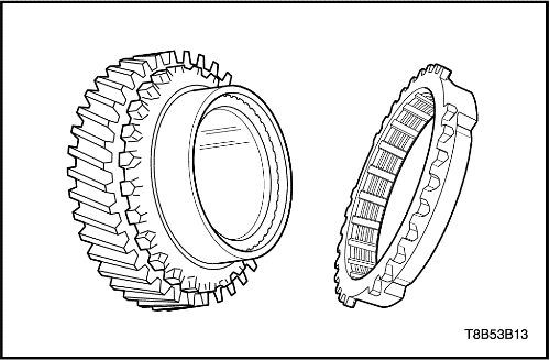
- Disassemble the third-fourth synchronizer hub assembly.
- Push the hub(1) from the synchronizer hub assembly.
- Disassemble the synchronizer sleeve (2) and the key units (3).
- Remove the input shaft third gear bearing (1).
Synchronizer Assembly Inspection
- Inspection wear of cone area.
- After matching synchronizer ring to gear, measure as shown in figure. Replace if it is below limit.
-
- Unit : mm (in.)
|
Clearance Between Gear and Ring
|
Standard
|
Limit
|
|
1.0 (0.039)
|
0.5 (0.020)
|
Important : Replace it by soaking new synchronizer ring at least five minutes in transaxle fluid (SAE 75W85W).
- Inspecting cone contact condition.
- When synchronizer mechanism is abnormal in operation, connection between ring inner surface and gear cone area is considered to be partially defective in spite of correct clearance between gear and ring. Therefore, cone area and ring inner surface shall be inspected. Cone area can be worn in wave form. Replace synchronizer ring and gear if necessary.
Important : Replace it by soaking new synchronizer ring at least five minutes in transaxle fluid (SAE 75W85W).
- Inspecting wear of synchronizer ring.
- Check for worn or damaged synchronizer ring teeth. Replace it if necessary.
Important : Replace it by soaking new synchronizer ring at least five minutes in transaxle fluid (SAE 75W85W).
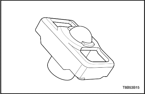
- Inspecting synchronizer key unit.
- Check for weak, damaged or broken spring.
Assembly Procedure
- Install the third gear bearing, the third gear / synchronizer ring.
-
- a. Third gear / synchronizer ring.
- b. Third gear bearing.
Important : Coat the inner parts; gear, bearing, oil seal etc. with gear fluid.
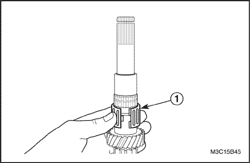
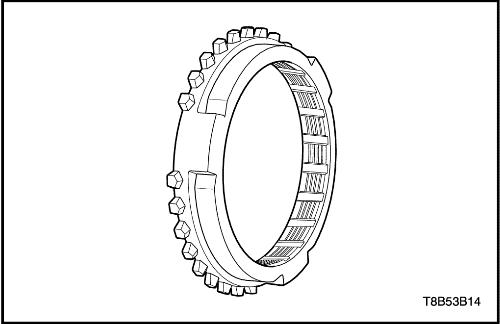
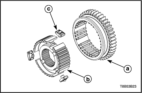
- Assemble the third-fourth synchronizer hub assembly.
- Install the hub to the sleeve.
- Install the key units into the key groove of sleeve and hub.
Important : Make sure that the key units is properly seated into the key groove of sleeve and hub.
-
- a. Sleeve
- b. Hub
- c. Key unit
- Install the third-fourth synchronizer hub assembly.
- Insert the hub assembly into the input shaft (1).
Important : Position the longer flange of hub toward the third gear and match the key groove of hub to the synchronizer ring lug.
- Install the hub assembly using a hammer and the gear, bearing installer DW09940-53111.
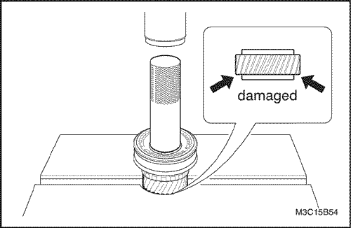
Notice : When installing gear, bearing and hub assembly, install them slowly using the gear, bearing installer DW09940-53111 and a hammer. If overpressed, the gear teeth may be damaged.
- Install the third-fourth synchronizer circlip.
- Install the fourth synchronizer ring.
Important : Match the synchronizer ring lug to the key groove of hub.
- Install the input shaft fourth gear bearing and the fourth gear.
-
- a. Fourth gear.
- b. Fourth gear bearing.

- Install the input shaft left side bearing and the fifth gear spacer.
- Install the following parts using the gear, bearing installer DT-49080 and a hammer.
-
- a. Fifth gear spacer.
- b. Input shaft left side bearing.
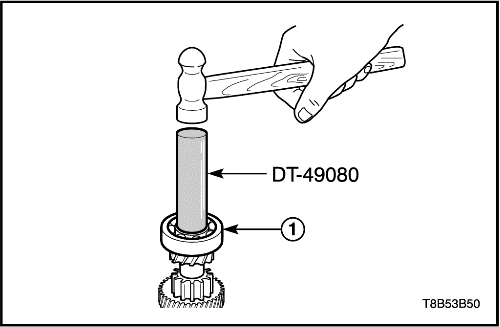
- Install the input shaft right side bearing.
- Install the bearing to the input shaft using the gear, bearing installer DT-49080 and a hammer (1).
- Install the gear unit. Refer to "Gear Unit"
in this section.
Counter Shaft
Tools Required
DW09921-57810 Gear, Bearing Remover
DT-49079 Gear, Bearing Installer
DT-49080 Gear, Bearing Installer
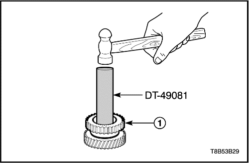
DT-49081 Gear, Bearing Installer
Disassembly Procedure
- Remove the gear unit. Refer to "Gear Unit"
in this section.
- Remove the counter shaft right side bearing.
- Remove the counter shaft left side bearing and the fourth gear.
- Position the fourth gear to the gear, bearing remover DW09921-57810.
- Remove the following parts by pressing.
-
- a. Counter shaft left side bearing.
- b. Fourth gear.
- Remove the counter shaft third-fourth gear spacer.
- Remove the counter shaft third gear and second gear.
- Position the second gear to the gear, bearing remover DW09921-57810.
- Remove the following parts by pressing.
-
- a. Third gear.
- b. Second gear.
- Remove the counter shaft second gear bearing.
- Remove the second gear synchronizer ring.
- Remove the first-second gear synchronizer circlip.
- Remove the counter shaft first-second gear synchronizer hub assembly, the first gear / the first gear synchronizer ring.
- Position the first gear to the gear, bearing remover DW09921-57810.
- Remove the following parts by pressing.
-
- a. Synchronizer hub assembly.
- b. First gear / First gear synchronizer ring.
- Remove the first gear synchronizer ring from the first gear.
- Disassemble the first-second gear synchronizer hub assembly.
- Push the hub (1) from the synchronizer hub assembly.
- Disassemble the synchronizer sleeve(2) and key units(3).
- Remove the counter shaft first gear bearing and the first gear spacer.
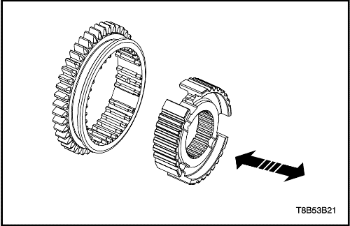
Synchronizer Hub and Sleeve Inspection
- Check the sleeve for improper operation after assembling the hub and the sleeve.
- Check the wear of hub and sleeve.
- Replace synchronizer hub or sleeve if necessary.

Assembly Procedure
- Install the related counter shaft first gear.
- Install the first gear spacer (1).
- Install the first gear bearing (2).
- Install the first gear (3).
- Install the first gear synchronizer ring (4).
Important : Coat the inner parts; gear, bearing and oil seal etc. with gear fluid.
- Assemble the first-second synchronizer hub assembly.
- Install the hub to the sleeve
- Install the key units into the key groove of sleeve and hub.
Important : Make sure that the key units is properly seated into the key groove of sleeve and hub.
-
- a. Sleeve.
- b. Hub.
- c. Key unit.
- Install the first-second synchronizer hub assembly.
- Insert the hub assembly into the counter shaft using the gear, bearing installer DT-49081 and a hammer (1).
Important : Match the key groove of hub to the first gear synchronizer ring lug.
- Install the first-second gear synchronizer circlip.
- Install the second synchronizer ring.
Important : Match the second synchronizer ring lug to the key groove of hub.
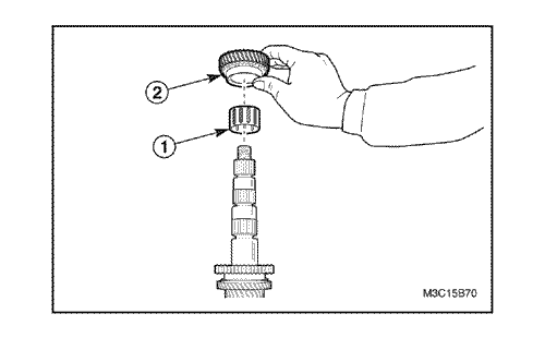
- Install the related counter shaft second gear.
- Install the second gear bearing (1).
- Install the second gear (2).
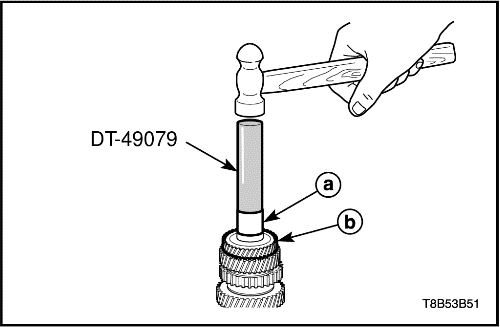
- Install the counter shaft third gear and the third-fourth gear spacer.
- Insert the third gear and the third-fourth gear spacer into the counter shaft.
- Install the following parts using the gear, bearing installer DT-49079 and a hammer.
-
- a. Third-fourth gear spacer.
- b. Third gear.
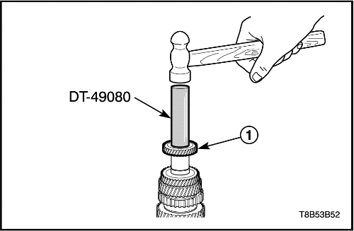
- Install the counter shaft fourth gear.
- Install the fourth gear to the counter shaft using the gear, bearing installer DT-49080 and a hammer (1).
- Install the counter shaft left side bearing.
- Install the left side bearing to the counter shaft using the gear, bearing installer DT-49080 and a hammer (1).
- Install the counter shaft right side bearing.
- Install the gear unit. Refer to "Gear Unit"
in this section.
Gear Shift Fork
Disassembly Procedure
- Remove the gear unit. Refer to "Gear Unit"
in this section.
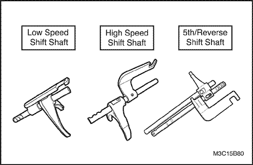
- Remove the each shift shaft assembly from the gear unit.
- Remove the first-second gear shift shaft assembly.
- Fix the shift shaft assembly to a vise with protector.
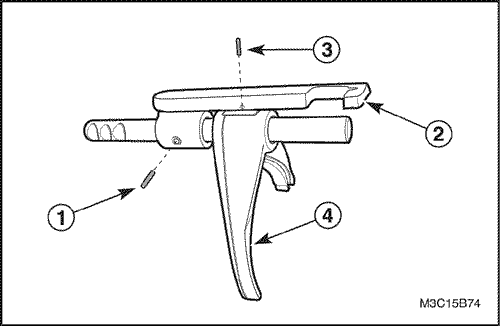
- Remove the first-second gear shift yoke pin using a pin punch and a hammer (1).
- Remove the first-second gear shift yoke (2).
- Remove the first-second gear fork pin using a pin punch and a hammer (3).
- Remove the first-second gear shift fork (4).
Important : Mark the place and direction of shift fork and yoke to install easily before removing them.
- Disassemble the third-fourth gear shift shaft assembly.
- Fix the third-fourth gear shift shaft assembly to a vise with protector.
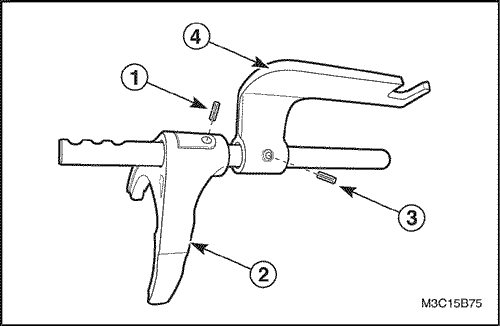
- Remove the third-fourth gear fork pin using a pin punch and a hammer (1).
- Remove the third-fourth gear fork (2).
- Remove the third-fourth gear shift yoke pin using a pin punch and a hammer (3).
- Remove the third-fourth gear shift yoke (4).
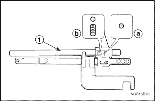
- Disassemble the fifth-reverse gear shift shaft assembly.
- Remove the shift shaft not installed with yoke by pushing (1).
- Remove the following parts from the reverse shift arm.
-
- a. Fifth-reverse gear ball.
- b. Reverse shift guide ball and spring.
- Fix the shift shaft assembly to a vise with protector.
- Remove the reverse gear shift arm pin using a pin punch and a hammer (2).
- Remove the reverse gear shift arm (3).
- Remove the fifth gear shift yoke pin using a pin punch and a hammer (4).
- Remove the fifth gear shift yoke (5).
Inspection Procedure - Shift Shaft
- Check for bent, deformed or damaged shift shaft.
- Replace shift shaft if necessary.
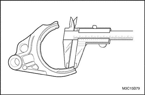
Inspection Procedure - Shift Fork
- Measure the end thickness of shift fork and replace if below limit.
-
- Unit : mm (in.)
|
Shift fork end
thickness (mm)
|
Standard
|
Limit
|
|
Low Speed Shift Fork
|
8.7 (0.343)
|
8.56 (0.337)
|
|
High Speed Shift Fork
|
7.8 (0.307)
|
7.66 (0.302)
|
|
Fifth Gear Shift Fork
|
7.8 (0.307)
|
7.66 (0.302)
|
Assembly Procedure
- Install in the reverse order of removal.
Important : Use only new fork fin and yoke pin.
Differential
Tools Required
09913-76010 Bushing, seal installer
DW220-020A-01 Differential Bearing Puller
DW220-020A-02 Differential Bearing Plate Adapter
DW220-020A-03 Differential Bearing Plate Adapter
Disassembly Procedure
- Remove the differential assembly. Refer to "Gear Unit"
in this section.
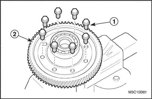
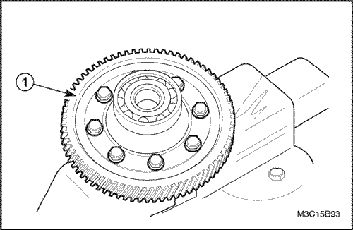
- Remove the differential ring gear.
- Fix the differential assembly to a vise with protector.
- Remove the bolts (1).
- Remove the ring gear (2).
- Fix the differential assembly to a vise with protector.
- Remove the bolts (1).
- Remove the ring gear (2).
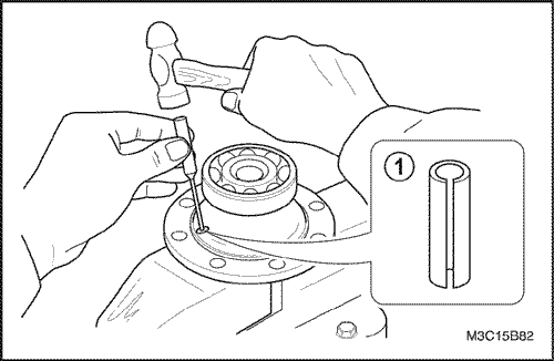
- Remove the pinion gear pin.
- Remove the pin using a pin punch and a hammer (1).
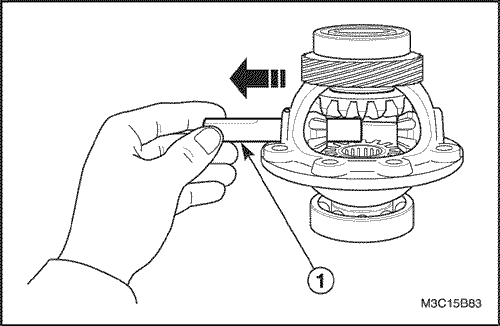
- Remove the pinion gear shaft.
- Remove the shaft from the case (1).
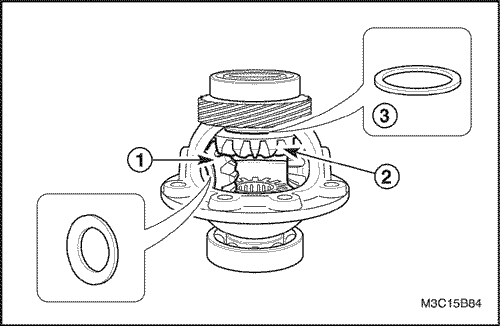
- Remove the pinion gears and the side gears.
- Remove the pinion gears and the washers (1).
Important : Remove the pinion gear and the washer by rotating the side gear.
- Remove the side gears (2).
- Remove the adjust shims from the side gears (3).
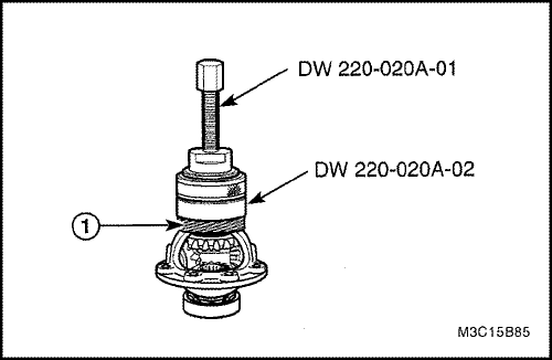
- Remove the differential right side bearing and speedometer drive gear.
- Remove the right side bearing using the differential bearing puller DW220-020A-01 and the differential bearing plate adapter DW220-020A-02.
- Remove the speedometer drive gear (1).
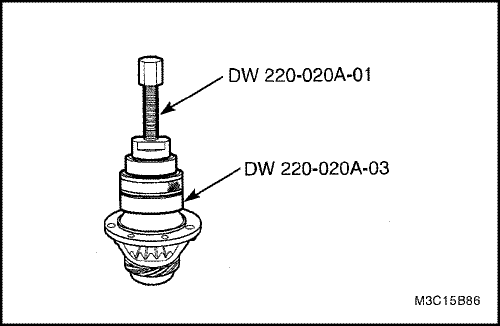
- Remove the differential left side bearing.
- Remove the left side bearing using the differential bearing puller DW220-020A-01 and the differential bearing plate adapter DW220-020A-03.
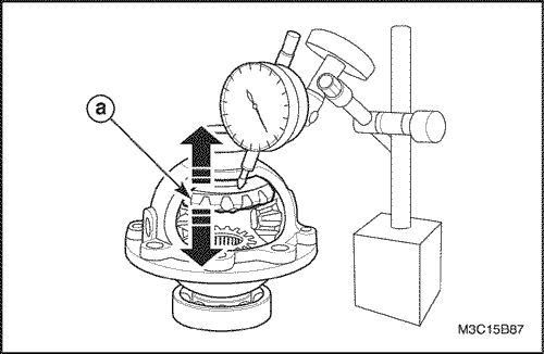
Side Gear Play Inspection
- Measure the axle direction play of side gear and replace a side gear washer if it exceeds limit.
-
- Unit : mm (in.)
|
Thrust Free Play of
Differential Side
|
0.03-0.4
(0.001-0.016)
|
-
- Unit : mm (in.)
|
Thrust
Adjusting
Shim
|
0.90(0.0354)-0.95(0.0374)
|
|
1.00(0.0394)-1.05(0.0413)
|
|
1.10(0.0433)-1.15(0.0453)
|
|
1.20(0.0472)
|
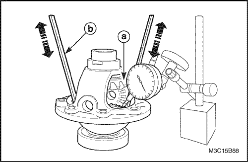
- After checking for worn or scratched thrust adjusting shim, replace it if necessary.
-
- a. Side gear.
- b. Driver.
Assembly Procedure
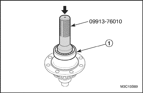
- Install the differential left side bearing.
- Insert the left side bearing (1).
- Install the left side bearing using the bushing, seal installer 09913-76010 and a hammer.
Important : Coat the inner parts; bearing, washer, shim etc. with gear fluid.
- Install the speedometer drive gear and differential right side bearing.
- Insert the speedometer drive gear(1).
- Insert the differential right side bearing (2).
- Install the right side bearing using the bushing, seal installer 09913-76010 and a hammer.
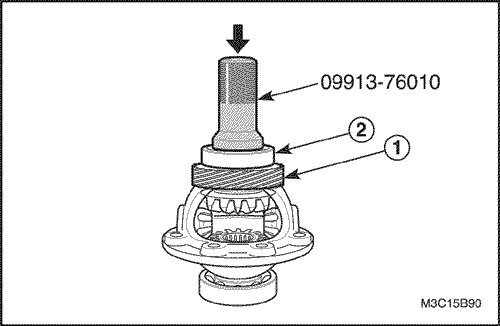
- Install the side gears and the pinion gears.
- Insert the trust adjusting shims to the side gears.
- Install the side gears (1).
- Install the pinion gears and washers (2).
Important : Install the pinion gears and washers simultaneously.
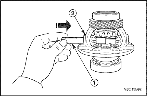
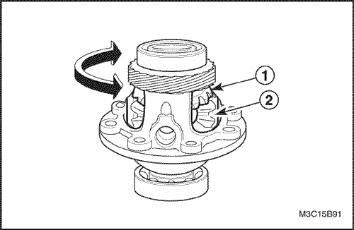
- Install the pinion gear shaft and pin.
- Insert the shaft into the gear pin hole by rotating (1).
- Press the pin using a pin punch and a hammer (2).
Important : Use only new pin.
- Install the differential ring gear.
- Fix the differential assembly to a vise.
- Install the ring gear with the bolts (1).
Tighten
Tighten the bolts to 80-100 N•m (59-74 lb-ft).
- Install the differential assembly. Refer to "Gear Unit"
in this section.
 |
|
 |
|
| © Copyright Chevrolet Europe. All rights reserved |


