SECTION 9L
GLASS AND MIRRORS
Caution : Disconnect the negative battery cable before removing or installing any electrical unit or when a tool or equipment could easily come in contact with exposed electrical erminals. Disconnecting this cable will help prevent personal injury and damage to the vehicle. The ignition must also be in LOCK unless otherwise noted.
SPECIFICATIONS
Fastener Tightening Specifications
|
Application
|
N•m
|
Lb-Ft
|
Lb-In
|
|
Exterior Rear Door Garnish Molding Screws
|
1.5
|
-
|
13
|
|
Door Glass Screws
|
7
|
-
|
62
|
|
Guide Rail Bolts
|
7
|
-
|
62
|
|
Outside Rearview Mirror Assembly Screws
|
4.5
|
-
|
40
|
|
Rearview Mirror Mounting Screw
|
1.2
|
-
|
11
|
SPECIAL TOOLS
Special Tools Table
 
|
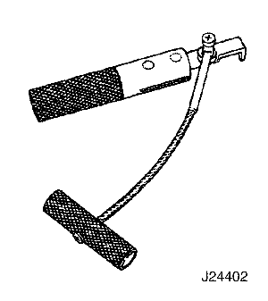
J-24402
Glass Sealant Remover
|
SCHEMATIC AND ROUTING DIAGRAMS
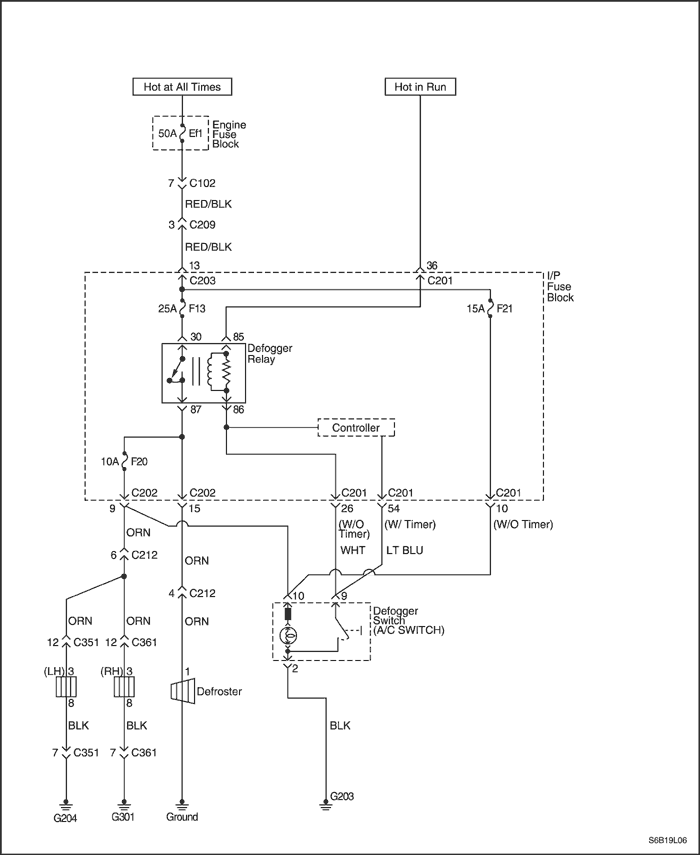
Rear Window and Outside Rear View Mirror Defogger
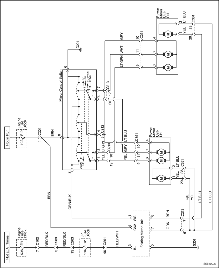
Electric Control Outside Rearview Mirror
DIAGNOSIS
Testing Rear Window Defogger Grid Line
If it has been observed during use that a grid line is inoperative, the following procedure can be used to find the break. If none of the grid lines is operating, a full system diagnosis should be completed before attempting to repair the grid lines.
- Turn the ignition ON.
- Turn the ignition ON.
- Turn on the rear window defogger.
- Turn on the rear window defogger.
Notice : Use care when touching the voltmeter terminals to a grid line. If the terminals are roughly applied, the grid line may be scratched, resulting in an open circuit.
- From the inside of the vehicle, connect a voltmeter to each end of a grid line. The voltmeter will indicate battery voltage if the grid line is open.
- If a grid line is found to be open, move a voltmeter terminal from one side of the grid line and retest at a point nearer to the other side of the window. Continue to retest, each time bringing one of the voltmeter terminals closer to the opposite side of the window from where it was originally connected. The break in the grid line is at the point where the voltmeter begins reading 0 volts instead of battery voltage.
- Use a marking crayon to lightly mark the break point on the rear window. Mark the glass instead of marking directly on the grid line, and make the mark far enough from the grid line so that the mark can easily be removed without disturbing the repair.
- Use a grid line repair kit to fix the break in the grid line. Refer to "Rear Window Defogger Grid Line Repair"
in this section.
Outside Rearview Mirror Defoggers
| Step |
Action |
Value(s) |
Yes |
No |
| 1 |
Check the rear window defogger.
Does the rear window defogger work?
|
-
|
Go to Step 4
|
Go to Step 2
|
| 2
|
Repair the rear window defogger before proceeding with the outside rearview mirror diagnosis.
Is the repair complete?
|
-
|
Go to Step 3
|
-
|
| 3 |
Test the outside rearview mirror defoggers.
Does the repair of the rear window defogger system also fix the problem with the outside rearview mirror defoggers?
|
-
|
System OK
|
Go to Step 4
|
| 4
|
Check fuse Ef1, F13(F21).
Is fuse Ef1, F13(F21) blown?
|
-
|
Go to Step 5
|
Go to Step 6
|
| 5 |
- Check for a short circuit and repair it, if necessary.
- Replace the fuse.
Is the repair complete?
|
-
|
System OK
|
-
|
| 6
|
- On the side of the vehicle which has the malfunctioning outside rearview mirror defogger, remove the black plastic escutcheon from the trim panel side of the door.
- Disconnect the outside rearview mirror electrical connector.
- Turn the ignition ON.
- Turn on the defogger.
- Use a voltmeter to backprobe terminal 3 (ORN) at the outside rearview mirror electrical connector.
Does the voltmeter indicate the specified value?
|
11-14 v
|
Go to Step 9
|
Go to Step 7
|
| 7 |
Repair the open circuit between fuse Ef1 and the defogger relay.
Is the repair complete?
|
-
|
System OK
|
Go to Step 8
|
| 8 |
- Turn the ignition ON.
- Turn on the defogger.
- use a voltmeter to fuse F13(F21) and the defogger relay terminal 30.
Does the voltmeter indicate the specified value?
|
11-14 v
|
Go to Step 10
|
Go to Step 9
|
| 9 |
Replace the defogger switch.
Is the repair complete?
|
-
|
System OK
|
Go to Step 10
|
| 10 |
Replace the defogger relay with other relay.
Does the outside rear view mirror work?
|
-
|
System OK
|
Go to Step 11
|
| 11 |
- Turn the ignition OFF.
- Disconnect the outside rearview mirror electrical connector.
- Use an ohmmeter to measure the resistance between terminal 8 (BLK) of the outside rearview mirror connector and ground.
Does the ohmmeter indicate the specified value?
|
≈ 0 Ω
|
Go to Step 13
|
Go to Step 12
|
| 12 |
Repair the open ground circuit for the outside rearview mirror.
Is the repair complete?
|
-
|
System OK
|
-
|
| 13 |
Replace the defective outside rearview mirror.
Is the repair complete?
|
-
|
System OK
|
-
|
Electric Control Outside Rearview Mirror
Outside Rearview Mirror Does Not Adjust
| Step |
Action |
Value(s) |
Yes |
No |
| 1
|
Check the electric control mirror's left-and-right and up-and-down adjustments.
Is the mirror operating for either the left-and-right or up-and-down adjustments?
|
-
|
Go to Step 12
|
Go to Step 2
|
| 2 |
Check fuse F19.
Is fuse F19 blown?
|
-
|
Go to Step 3
|
Go to Step 4
|
| 3 |
- Check for a short circuit and repair it, if necessary.
- Replace fuse F19.
Is the repair complete?
|
-
|
System OK
|
-
|
| 4 |
- Turn the ignitionON.
- Check the voltage at fuse F19.
Is the voltage at fuse F19 equal to the specified value?
|
11-14 v
|
Go to Step 6
|
Go to Step 5
|
| 5 |
Repair the open power supply circuit for fuse F19.
Is the repair complete?
|
-
|
System OK
|
-
|
| 6 |
- From below the instrument panel, reach up and press one of the retaining tabs for the electric control mirror switch trim panel.
- While pressing one of the retaining tabs, pull the switch assembly away from the instrument panel so that the connector is visible.
Is the connector properly connected to the electric control mirror switch?
|
-
|
Go to Step 8
|
Go to Step 7
|
| 7 |
Connect the connector to the electric control mirror switch.
Is the repair complete?
|
-
|
System OK
|
-
|
| 8 |
- Disconnect the electric control mirror switch connector.
- Turn the ignition ON.
- Connect a voltmeter between terminal 8 (BRN) and terminal 6 (BLK).
Does the voltmeter indicate the specified value?
|
11-14 v
|
Go to Step 13
|
Go to Step 9
|
| 9 |
- Turn the ignition ON.
- Check the voltage at terminal 8 (BRN).
Does the voltage equal the specified value?
|
11-14 v
|
Go to Step 10
|
Go to Step 11
|
| 10 |
Repair the open circuit between ground and terminal 6 (BLK).
Is the repair complete?
|
-
|
System OK
|
-
|
| 11 |
Repair the open circuit between the power window relay and the electric control mirror switch.
Is the repair complete?
|
-
|
System OK
|
-
|
| 12 |
Check the left-and-right adjustment for the electric control mirror.
Is the left-and-right adjustment working for the electric control mirror?
|
-
|
Go to Step 18
|
Go to Step 13
|
| 13 |
- Make sure the electric control mirror switch has been reconnected.
- On the passenger door, remove the black plastic escutcheon to expose the electric control mirror connector.
- Disconnect the connector at the passenger door electric control mirror.
- Connect a voltmeter between terminal 4 and terminal 7.
- Observe the voltmeter while operating the electric control mirror switch to select the left-and-right adjustment.
Does the voltmeter indicate the specified voltage in one direction, and the same voltage with reverse polarity when operated in the opposite direction?
|
11-14 v
|
Go to Step 17
|
Go to Step 14
|
| 14 |
- Disconnect the electric control mirror switch connector.
- Use an ohmmeter to measure the continuity between terminal 7 at the electric control mirror switch and terminal 5 (LT BLU) at the power mirror connector.
- Use an ohmmeter to measure the continuity between terminal 4 (GRY) at the electric control mirror switch and terminal 4 at the power mirror connector.
Does the ohmmeter indicate the specified value for both measurements?
|
≈ 0 Ω
|
Go to Step 16
|
Go to Step 15
|
| 15 |
Repair the open circuit between the electric control mirror switch and the electric control mirror connector.
Is the repair complete?
|
-
|
System OK
|
-
|
| 16 |
Replace the electric control mirror switch.
Is the repair complete?
|
-
|
System OK
|
-
|
| 17 |
Replace the electric control mirror.
Is the repair complete?
|
-
|
System OK
|
-
|
| 18 |
- If the electric control mirror switch was previously disconnected for testing, make sure it is reconnected.
- Disconnect the electric control mirror connector at the passenger door power mirror.
- Connect a voltmeter between terminal 4 and terminal 6.
- Observe the voltmeter while operating the power mirror switch to select the up-and-down adjustment.
Does the voltmeter indicate the specified voltage in one direction, and the same voltage with reverse polarity when operated in the opposite direction?
|
11-14 v
|
Go to Step 17
|
Go to Step 19
|
| 19 |
- Disconnect the electric control mirror switch connector.
- Use an ohmmeter to measure the continuity between terminal 1 (YEL) at the electric control mirror switch and terminal 6 at the electric control mirror connector.
- Use an ohmmeter to measure the continuity between terminal 4 at the electric control mirror switch and terminal 4 (GRY) at the electric control mirror connector.
Does the ohmmeter indicate the specified value for both measurements?
|
≈ 0 Ω
|
Go to Step 16
|
Go to Step 15
|
MAINTENANCE AND REPAIR
ON-VEHICLE SERVICE
Windshield
Tools Required
J-24402 Glass Sealant Remover
Removal Procedure
- Remove the cowl vent grille. Refer to Section 9R,
Body Front End.
- Remove the inside rearview mirror. Refer to "Inside Rearview Mirror"
in this section.
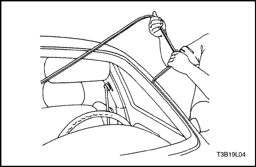
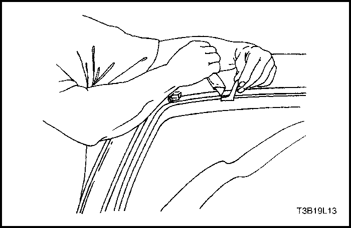
- Remove the weatherstrip around the windshield.
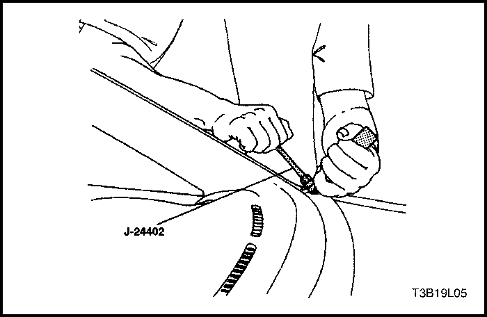
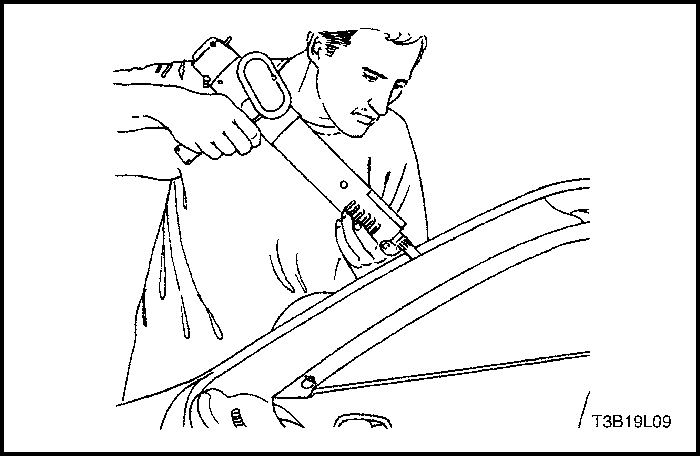
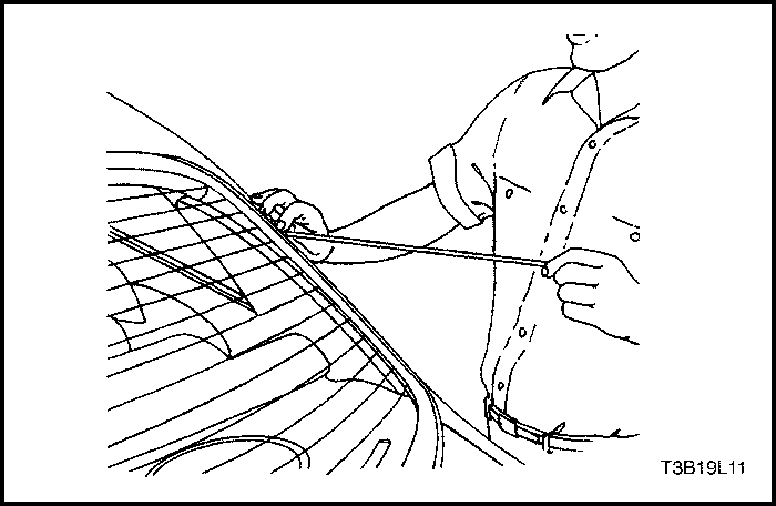
- Using the glass sealant remover J-24402, cut the adhesive around the windshield.
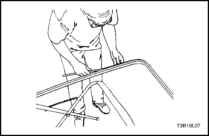
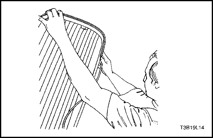
- Remove the windshield from the vehicle.
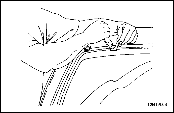
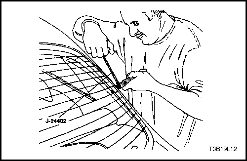
- Using a knife, remove the adhesive from the windshield.
- Using a knife, remove the adhesive from the windshield frame.
Installation Procedure
- Install the new weatherstrip to the windshield.
- Apply tape to the new weatherstrip and the windshield to hold the weatherstrip in place.
- Apply adhesive primer to the windshield frame and the perimeter of the windshield.
- Apply glass adhesive to the windshield frame.
- Install the windshield into the windshield frame.
- Reposition the tape over the weatherstrip, the windshield, and the windshield frame to hold the windshield in place.
- Let the adhesive dry for 24 hours.
- Remove the tape.
- Check for waterleaks by pouring water on the windshield. If a leak is found, dry the windshield and fill the area that leaks with adhesive. If the leak persists, remove the windshield and repeat the entire procedure.
- Install the inside rearview mirror. Refer to "Inside Rearview Mirror"
in this section.
- Install the cowl vent grille. Refer to Section 9R,
Body Front End.
Rear Window Glass
Tools Required
J-24402 Glass Sealant Remover
Removal Procedure
- Disconnect the negative battery cable.
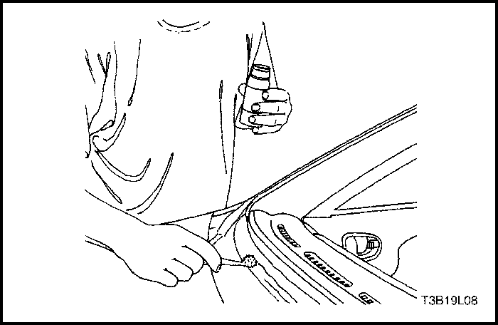
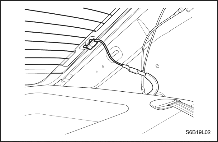
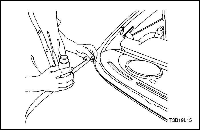
- Disconnect the rear window defogger electrical connectors (left side electrical connector shown, right side electrical connector similar).
- Remove the weatherstrip around the rear window.
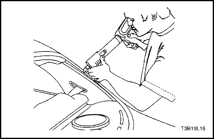
- Using the glass sealant remover J-24402, cut the adhesive around the rear window.
- Remove the rear window from the vehicle.
- Using a knife, remove the adhesive from the rear window.
- Using a knife, remove the adhesive from the rear window frame.
Installation Procedure
- Install the new weatherstrip to the rear window.
- Apply tape to the new weatherstrip and the rear window to hold the weatherstrip in place.
- Apply adhesive primer to the rear window frame and the perimeter of the rear window.
- Apply glass adhesive to the rear window frame.
- Install the rear window into the rear window frame.
- Reposition the tape over the weatherstrip, the rear window, and the rear window frame to hold the rear window in place.
- Let the adhesive dry for 24 hours.
- Remove the tape.
- Check for waterleaks by pouring water on the rear window. If a leak is found, dry the window and fill the area that leaks with adhesive. If the leak persists, remove the rear window and repeat the entire procedure.
- Connect the rear window defogger electrical connectors (left side electrical connector shown, right side electrical connector similar).
- Connect the negative battery cable.
Rear Window Defogger Grid Line Repair
- Disconnect the negative battery cable.
- Disconnect the rear window defogger electrical connectors (left side electrical connector shown, right side electrical connector similar).
- Inspect the rear window defogger grid lines.
- Mark the grid line break on the outside of the glass with a wax pencil or a crayon.
- Use steel wool to buff the grid lines that are to be repaired. Wipe the lines clean using a cloth dampened with alcohol. Buff and clean about 6 mm (0.25 inch) beyond each side of the break in the grid line.
- Attach a grid line repair decal or two strips of tape above and below the repair areas.
- A repair decal or tapemust be used in order to control the width of the repair areas.
- If a decal is used, the die-cut metered slot must be the same width as the grid line.
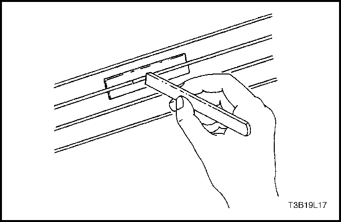
- Apply the grid repair material to the repair area using a small wooden stick or a spatula. The grid repair material should be at room temperature.
- Carefully remove the decal or the tape.
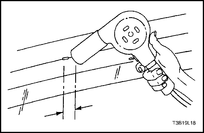
Notice : The grid line repair material must be cured with heat. In order to avoid heat damage to the interior trim, protect the trim near the repair area where heat will be applied.
- Heat the repair area for 1 to 2 minutes.
- Hold the heat gun nozzle 25 mm (1 inch) from the surface. A minimum temperature of 149°C (300°F) is required.
- Inspect the grid line repair area. If the repair appears discolored, apply a coating of tincture of iodine to the area using a pipe cleaner or a line brush. Allow the iodine to dry for about 30 seconds. Carefully wipe off the excess iodine with a lint-free cloth.
- Connect the rear window defogger electrical connectors.
- Test the operation of the rear window defogger in order to verify that the repair was successful.
Important : At least 24 hours is required for complete curing of the repair materials. The repair area should not be physically disturbed until after that time.

Rear window Defogger Braided Lead Wire Repair
The rear window defogger bus lead wire or the terminal can be reattached by resoldering. Use a solder containing 3 percent silver and a rosin flux paste.
- The repair area should be buffed with fine steel wool before soldering the bus lead wire.
- Apply the paste-type rosin flux in small quantities to the wire lead and the bus lead wire repair area using a brush.
- Coat the soldering iron tip with solder. Use only enough solder to ensure a complete repair.
- Use only enough heat to melt the solder. Do not overheat the wire when resoldering to the bus lead wire.
Front Door Glass
Removal Procedure
- Remove the front door trim panel. Refer to Section 9G, Interior Trim.
- Remove the door seal trim. Refer to Section 9P, Doors.
- Remove the outside channel molding. Refer to Section 9P, Doors.
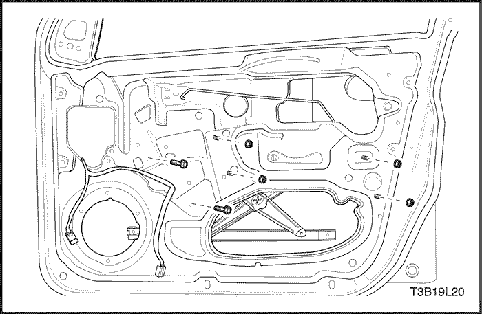
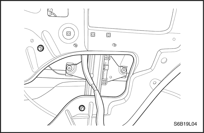
- Remove the screws that secure the glass to the window regulator.
- Remove the bolts and the guide rail.
- Remove the glass from the door.
Installation Procedure
- Install the glass in the door.
- Install the guide rail and the bolts.
Tighten
Tighten the guide rail bolts to 7 N•m (62 lb-in).
- Install the glass to the window regulator with the screws.
Tighten
Tighten the door glass screws to 7 N•m (62 lb-in).
- Install the outside channel molding. Refer to Section 9P, Doors.
- Install the door seal trim. Refer to Section 9P, Doors.
- Install the front door trim panel. Refer to Section 9G, Interior Trim.
Rear Door Glass
Removal Procedure
- Remove the rear door trim panel. Refer to Section 9G, Interior Trim.
- Remove the outside channel molding. Refer to Section 9P, Doors.
- Remove the interior rear door garnish molding.
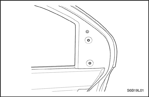
- Remove the screws and the exterior rear door garnish molding.
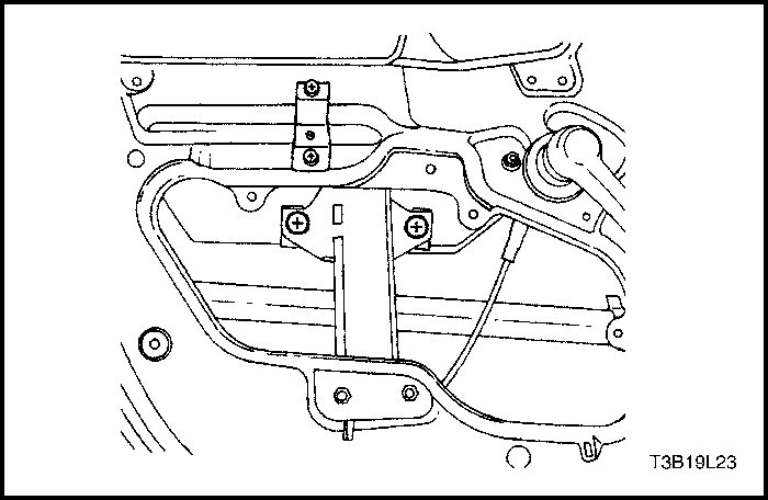
- Remove the screws that secure the glass to the window regulator.
- Remove the guide rail.
- Remove the glass from the door.
Installation Procedure
- Install the glass in the door.
- Install the guide rail.
Tighten
Tighten the guide rail bolts to 7 N•m (62 lb-in).
- Position the glass within the window regulator.
- Install the glass screws.
Tighten
Tighten the door glass screws to 7 N•m (62 lb-in).
- Install the door seal trim. Refer to Section 9P, Doors.
- Install the exterior rear door garnish molding with the screws.
Tighten
Tighten the exterior rear door garnish molding screws to 1.5 N•m (13 lb-in).
- Install the interior rear door garnish molding.
- Install the outside channel molding. Refer to Section 9P, Doors.
- Install the rear door trim panel. Refer to Section 9G, Interior Trim.
Inside Rearview Mirror Support
The inside rearview mirror is attached to a support which is secured to the windshield glass. The support is installed by the glass supplier using a plastic-polyvinyl butyl adhesive.
Service replacement windshield glass has the mirror support bonded to the glass assembly. In order to install a detached mirror support or install a new part, the following items will be needed:
- Loctite® Minute-Bond Adhesive.
- Original or replacement mirror support.
- Wax marking pencil or crayon.
- Rubbing alcohol.
- Clean paper towel.
- Fine grit sandpaper (grit #320 or #360).
- 2 mm allen wrench.
Installation Procedure
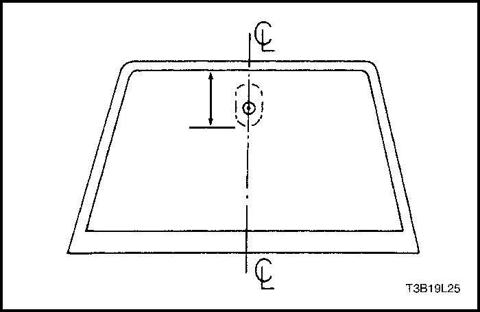
- Measure the distance from the headliner to the bottom of where the mirror support will be mounted on the windshield.
- Mark this position on the outside of the glass with a wax pencil or crayon. Draw a large diameter circle on the outside of the glass around the mirror support location.
- Clean the inside surface of the glass with paper towels and a domestic scouring cleanser, a glass cleaning solution, or a polishing compound. Rub the glass until the area is completely dry. When the area is dry, clean the area with an alcohol-saturated paper towel in order to remove any traces of scouring powder or glass cleaning solution.
- If the mirror support is new, clean the bonding surface with fine grit sandpaper #320 or #360. If the original mirror support is being used, all traces of factoryinstalled adhesive must be removed prior to reinstallation.
- Wipe the sanded mirror support with a clean paper towel saturated with rubbing alcohol. Allow the support to dry.
- Follow the adhesive kit manufacturer's directions for adhesive application and mirror support preparation before installing the mirror support to the glass.
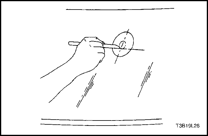
- Position the mirror support to its premarked position. Use steady pressure and press the support against the glass for 30 to 60 seconds.
- After 5 minutes, remove the excess adhesive with an alcohol-moistened towel or a glass cleaning solution.
- Install the inside rearview mirror to the mirror support with the mounting screw.
Tighten
Tighten the rearview mirror mounting screw to 1.2 N•m(11 lb-in).
Inside Rearview Mirror
Removal Procedure
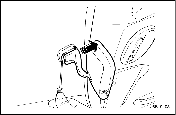
- Using a flat-blade screwdriver, pry off the mirror from the support and slide it back.
Installation Procedure
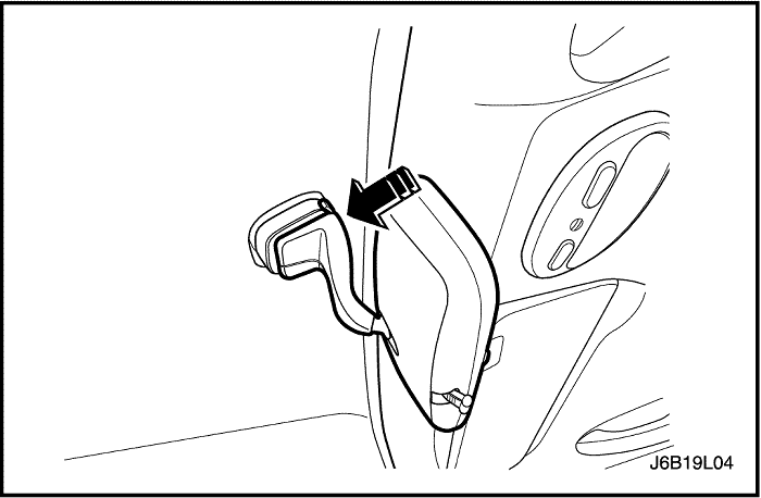
- Slide the inside rearview mirror from the rear of the support frontward, ensuring that it is pushed in fully into the support.
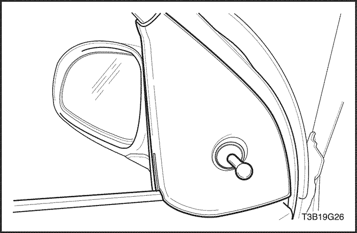
Outside Rearview Mirrors
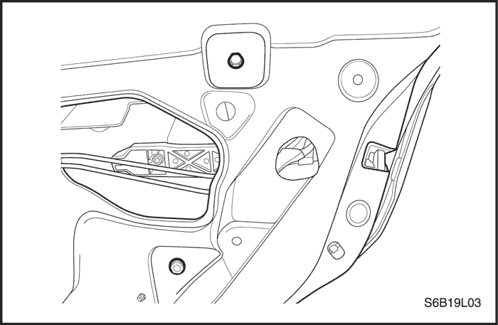
Removal Procedure
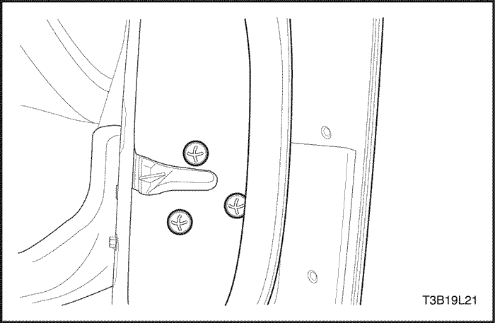
- Remove the front door escutcheon. (Manual remote control mirror shown.)
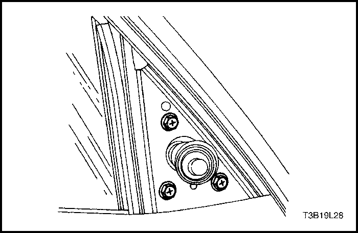
- Disconnect the electric control rearview mirror electrical connector, if equipped.
- Remove the screws and the outside rearview mirror assembly from the door. (Manual remote control mirror shown.)
Installation Procedure
- Install the outside rearview mirror assembly to the door with the screws.
Tighten
Tighten the outside rearview mirror assembly screws to 4.5 N•m (40 lb-in). (Manual remote control mirror shown.)
- Connect the electric control rearview mirror electrical connector, if equipped.
- Install the escutcheon. (Manual remote control mirror shown.
GENERAL DESCRIPTION AND SYSTEM OPERATION
Stationary Glass
Stationary glass consists of all the glass on the vehicle which is immovable within its frame, such as the windshield glass, the back glass, and the inside rearview mirror.
Inside Rearview Mirror
The inside rearview mirror can be manually adjusted up/ down, fore/aft, and left/right. The rearview mirror pivots in two places: the ball-and-socket mirror pivot and the up/down hinge lever at the mirror support.
Outside Rearview Mirrors
Two types of outside rearview mirrors are available. The driver side is equipped with a remote control mirror. On the passenger side, a remote control mirror is standard, and an electric remote control mirror is optional. The electric control outside rearview mirror can be adjusted by an electric control switch on the instrument panel.