SECTION 9R
BODY FRONT END
SPECIFICATIONS
Fastener Tightening Specifications
Application
|
N•m
|
Lb-Ft
|
Lb-In
|
|
Cowl Vent Grille Screws
|
3
|
-
|
27
|
|
Fender Screws (Rear of Fascia)
|
4
|
-
|
35
|
|
Fender-to-A-Pillar Bolt
|
8
|
-
|
71
|
|
Fender Bolt
|
8
|
-
|
71
|
|
Fender Line Nut
|
13
|
-
|
113
|
|
Fender Liner Bolt
|
1.5
|
-
|
13
|
|
Fender Liner-to-Mudguard Bolt
|
1.5
|
-
|
13
|
|
Front Bumper Fascia-to-Fender Screw
|
1.5
|
-
|
13
|
|
Hinge Bolts
|
20
|
15
|
-
|
|
Hood Latch Screws
|
8
|
-
|
71
|
|
Hood Release Handle Screws
|
1.5
|
-
|
13
|
|
Hood-to-Hinge Bolts
|
20
|
15
|
-
|
|
Lower Fender Bolts
|
10
|
-
|
89
|
|
Splash Shield Screws
|
1.5
|
-
|
13
|
|
Upper Fender Bolts
|
10
|
-
|
89
|
MAINTENANCE AND REPAIR
On-Vehicle Service
Lubrication
The hood hinges and the locking mechanisms require periodic lubrication for proper operation. Refer to
Section 0B, General Information for the specific types and intervals of lubrication.
Fasteners
Notice : Dissimilar metals in direct contact with each other may corrode rapidly. Make sure to use the correct fasteners to prevent premature corrosion.
Many aluminum components are used on current models. Aluminum in contact with steel may corrode rapidly if it is not protected by special finishes or isolators.
The fasteners used have a special finish which provides adequate protection from corrosion. These special fasteners differ in color in order to easily identify them from the standard metric fasteners, which are medium blue in color.
When replacing fasteners, avoid substituting otherwise similar fasteners in the same location.
Anticorrosion Materials
In order to provide rust resistance, anticorrosion materials have been applied to the interior surfaces of most of the metal panels. When servicing these panels, properly re-coat them with a service-type anticorrosion material if any of the original material has been disturbed.
Front End Sealing
All locations where waterleaks may occur are sealed during production with high quality, durable sealers. If it becomes necessary to reseal specific areas, use a high quality sealer of medium-bodied consistency which will retain its flexible characteristics after drying and can be painted, if necessary.
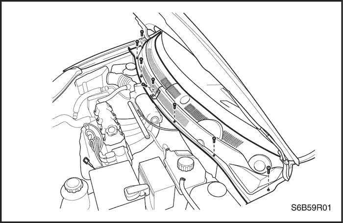


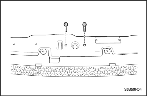
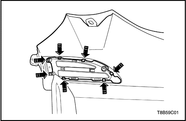
Cowl Vent Grille
Removal Procedure
- Raise the hood and support it with the hood prop.
- Remove the nuts and the wiper arms.
- Remove the cowl vent grille screws and the two-piece grille.
Installation Procedure
Notice : Dissimilar metals in direct contact with each other may corrode rapidly. Make sure to use the correct fasteners to prevent premature corrosion.
- Install the two-piece grille and the cowl vent grille screws.
Tighten
Tighten the cowl vent grille screws to 3 N•m (27 lb-in).
- Install the nuts and the wiper arms.
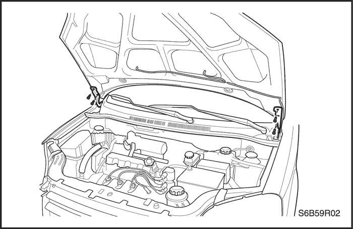
Hood
Removal Procedure
Important : Install protective coverings over the fenders and the windshield in order to prevent damage to the paint, the glass, and the moldings when removing and installing the hood.
- Raise and support the hood.
- Remove the washer hose.
- Mark the position of the hinge to the hood in order to aid in alignment during installation.
- Remove the bolts retaining the hood to both hinges.
- With the aid of another technician, remove the hood from the hinges.
Installation Procedure
- With the aid of another technician, position the hood in the location marked during removal.
Notice : Dissimilar metals in direct contact with each other may corrode rapidly. Make sure to use the correct fasteners to prevent premature corrosion.
- Install the two bolts securing the hood to each hinge.
Tighten
Tighten the hood-to-hinge bolts to 20 N•m (15 lb-ft).
- Install the washer hose.
- Inspect the hood for proper alignment.
Hood Hinges
Removal Procedure
- Remove the hood. Refer to "Hood"
in this section.
- Remove the fender. Refer to "Fender"
in this section.
- Remove the bolts and the hinge.
Installation Procedure
Notice : Dissimilar metals in direct contact with each other may corrode rapidly. Make sure to use the correct fasteners to prevent premature corrosion.
- Install the hinge with the bolts.
Tighten
Tighten the hinge bolts to 20 N•m (15 lb-ft).
- Install the fender. Refer to "Fender"
in this section.
- Install the hood. Refer to "Hood"
in this section.
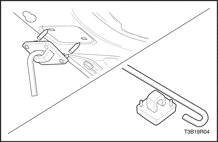
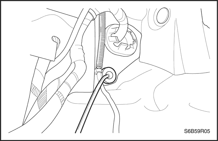
Hood Prop Rod
Removal Procedure
- Support the hood in the open position.
- Remove the hood prop rod by gently prying the base from the radiator support.
Installation Procedure
- Install the hood prop rod by snapping the base back into the radiator support.
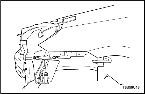
Hood Secondary Latch
Removal Procedure
- Open the hood.
- Remove the screws and the hood latch.
- Disconnect the hood release cable.
Installation Procedure
- Connect the hood release cable to the latch.
Notice : Dissimilar metals in direct contact with each other may corrode rapidly. Make sure to use the correct fasteners to prevent premature corrosion.
- Install the hood latch with the screws.
Tighten
Tighten the hood latch screws to 8 N•m (71 lb-in).
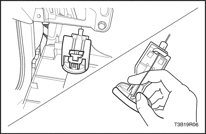
Hood Latch Release Cable
Removal Procedure
- Pull out the hood release handle in order to access the screws.
- Remove the screws and the hood release handle from the instrument panel.
- Raise and suitably support the vehicle.
- Remove the front left wheel. Refer to Section 2E, Tires and Wheels.
- Remove the screws and the splash shield.
- Open the hood.
- Remove the screws and the hood secondary latch.
- Remove the cable from the hood release handle.
- Remove the cable from inside the vehicle.
Installation Procedure
- Install the cable from inside the vehicle.
- Install the cable to the hood release handle.
Notice : Dissimilar metals in direct contact with each other may corrode rapidly. Make sure to use the correct fasteners to prevent premature corrosion.
- Install the screws and the hood secondary latch.
Tighten
Tighten the hood latch screws to 8 N•m (71 lb-in).
- Install the splash shield with the screws.
Tighten
Tighten the splash shield screws to 1.5 N•m(13 lb-in).
- Install the front wheel. Refer to Section 2E, Tires and Wheels.
- Lower the vehicle.
- Install the hood release handle on the instrument panel with the screws.
Tighten
Tighten the hood release handle screws to 1.5 N•m (13 lb-in).
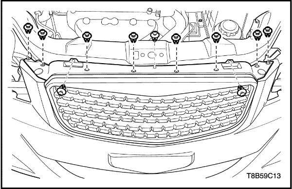
Radiator Grille
Removal Procedure
- Open the hood.
- Remove the front bumper fascia. Refer to Section 9O, Bumpers and Fascias.
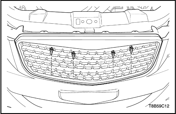
- Remove the screws and the radiator grille.
Installation Procedure
Notice : Dissimilar metals in direct contact with each other may corrode rapidly. Make sure to use the correct fasteners to prevent premature corrosion.
- Install the radiator grille with the screw.
- Install the front bumper fascia. Refer to Section 9O, Bumpers and Fascias.
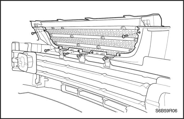
Radiator Grille - Hatchback -
Removal Procedure
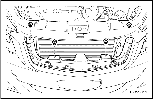
- Remove the clips on the radiator grille.
- Remove the radiator grille upper cover.
- Remove the radiator grille-to-front bumper clips after removing the radiator grille upper cover.
- Remove the radiator grille.
- Remove the front bumper air guard clips.
- Remove the front bumper air guard.
- Install the front bumper air guard.
- Install the front bumper air guard clips.
Installation Procedure
- Install the front bumper air guard.
- Install the front bumper air guard clips.
- Install the radiator grille-to-front bumper clips.
- Install the radiator grille.
- Install the radiator grille upper cover.
- Install the clips on the radiator grille.
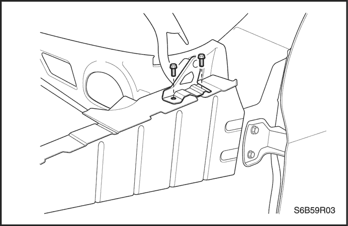
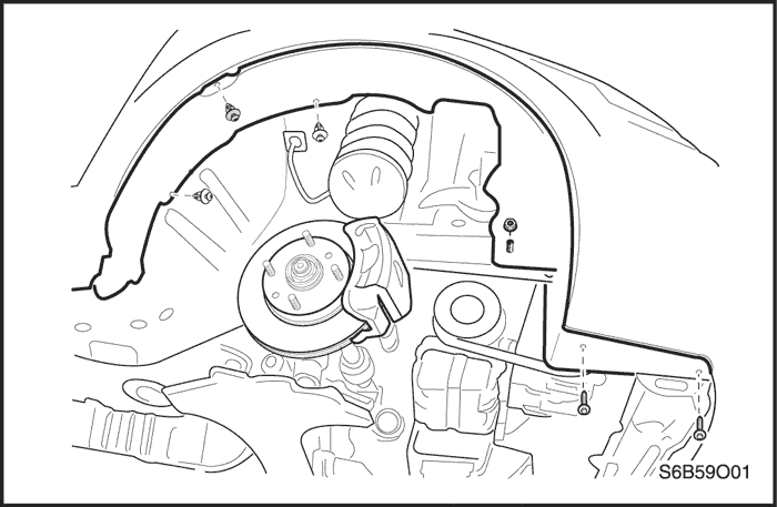
Fender
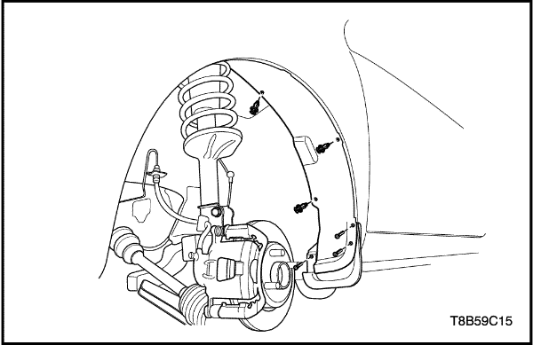
Removal Procedure
- Raise and suitably support the vehicle.
- Remove the front wheel. Refer to Section 2E, Tires and Wheels.
- Remove the bolts and the splash shield.
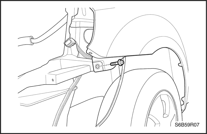
- Remove the screws underneath the front bumper fascia.
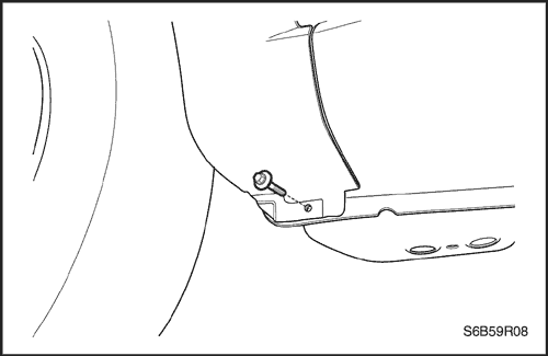
- Remove the screw securing the front bumper fascia to the fender.
- Remove the bolts at the base of the fender.
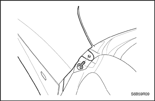
- Open the front door. Remove the bolt at the base of the A-pillar.
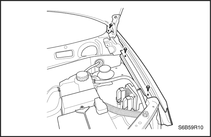
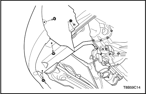
- Open the hood.
- Remove the headlamp. Refer to Section 9B, Lighting Systems.
- Remove the bolts along the top of the fender.
- Remove the fender.
Installation Procedure
- Install the headlamp. Refer to Section 9B, Lighting Systems.
- Install the fender.
Notice : Dissimilar metals in direct contact with each other may corrode rapidly. Make sure to use the correct fasteners to prevent premature corrosion.
- Install the bolts along the top of the fender.
Tighten
Tighten the upper fender bolts to 8 N•m (71 lb-in).
- Install the bolt at the base of the A-pillar.
Tighten
Tighten the fender-to-A-pillar bolt to 8 N•m (71 lb-in).
- Install the bolts at the base of the fender.
Tighten
Tighten the lower fender bolts to 8 N•m (71 lb-in).
- Secure the fender to the front bumper fascia with the screw.
Tighten
Tighten the front bumper fascia screw to 1.5 N•m (13 lb-in).
- Secure the fender behind the front bumper fascia with the screws.
Tighten
Tighten the fender screws to 4 N•m (35 lb-in).
- Install the splash shield with the screws.
Tighten
Tighten the splash shield screws to 1.5 N•m(13 lb-in).
- Install the front wheel. Refer to Section 2E, Tires
and Wheels.
- Lower the vehicle.
Fender and Fender Liner - Hatchback -
Removal Procedure
- Raise and suitably support the vehicle.
- Remove the front wheel. Refer to Section 2E, Tires and Wheels.
- Remove the fender liner-to-mudguard bolts and fender liner clips.
- Remove the fender liner nuts and bolts.
- Remove the head lamps. Refer to Section 9B, Lighting Systems.
- Remove the radiator grille. Refer to "Radiator Grille (Hatchback)"
in this section.
- Remove the front bumper fascia. Refer to Section 9O, Bumpers and Fascias.
- Remove the wiper arms. Refer to Section 9D, Wipers/Washer Systems.
- Remove the left side portion of cowl vent grille. Refer to "Cowl Vent Grille"
in this section.
- Remove the side turn signal lamp. Refer to Section 9B, Lighting Systems.
- Remove the fender bolts along the top of the fender.
- Open the front door. Remove the bolt at the base of the A-pillar.
- Remove the bolt at the base of the fender.
- Remove the fender bolts.
- Remove the fender.
Installation Procedure
- Install the fender.
- Install the fender bolts.
Tighten
Tighten the fender bolts to 8 N•m (71 lb-in).
- Install the fender bolt at the base of the fender.
Tighten
Tighten the fender bolts to 8 N•m (71 lb-in).
- Install the fender bolt at the base of the A-pillar.
Tighten
Tighten the fender bolts to 8 N•m (71 lb-in).
- Install the fender bolts along the top of the fender.
Tighten
Tighten the fender bolts to 8 N•m (71 lb-in).
- Install the side turn signal lamp. Refer to Section 9B, Lighting Systems.
- Install the left side portion of cowl vent grille. Refer to "Cowl Vent Grille"
in this section.
- Install the wiper arms. Refer to Section 9D, Wipers/Washer Systems.
- Install the front bumper fascia. Refer to Section 9O, Bumpers and Fascias.
- Install the radiator grille. Refer to "Radiator Grille (Hatchback)"
in this section.
- Install the head lamps. Refer to Section 9B, Lighting Systems.
- Install the fender liner nuts and bolts.
Tighten
- Tighten the fender liner nuts to 13 N•m(113 lb-in).
- Tighten the fender liner bolts to 1.5 N•m(13 lb-in).
- Install the fender liner-to-mudguard bolts and fender liner clips.
Tighten
Tighten the fender liner-to-mudguard bolts to 1.5 N•m (13 lb-in).
- Install the front wheel. Refer to Section 2E, Tires and Wheels.
- Lower the vehicle.
Fender Molding - Hatchback -
Removal Procedure
- Remove the fender. Refer to "Fender and Fender Liner"
in this section.
- Remove the fender molding by pushing out it from inside of the fender.
Installation Procedure
- Install the fender molding.
GENERAL DESCRIPTION
AND SYSTEM OPERATION
Body Front End
This vehicle has a unitized body with a frame assembly supporting the engine and the transaxle. The fender panels and the radiator support are also integral parts of the body.


