Aveo |
||||||||
|
||||||||
|
Application
|
N•m
|
Lb-Ft
|
Lb-In
|
|
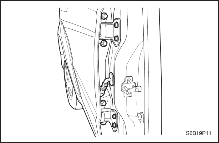
Door Hinge-to-Body Bolts
|
20
|
15
|
-
|
|
Door Hinge-to-Door Bolts
|
20
|
15
|
-
|
|
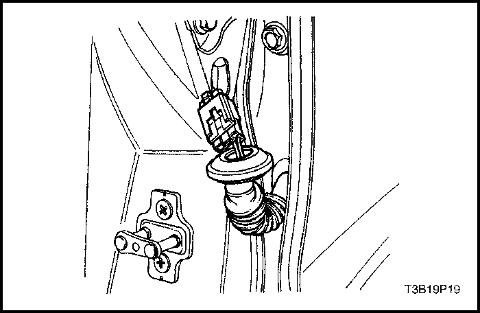
Door Hold Open Link-to-Body Bolts
|
35
|
26
|
-
|
|
Door Hold Open Link-to-Door Bolts
|
5
|
-
|
44
|
|
Door Lock Screws
|
8
|
-
|
71
|
|
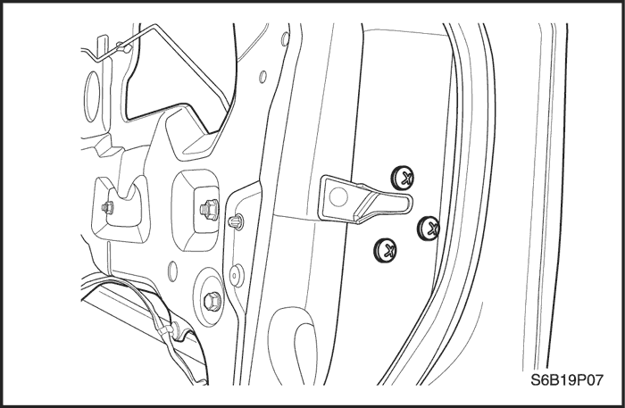
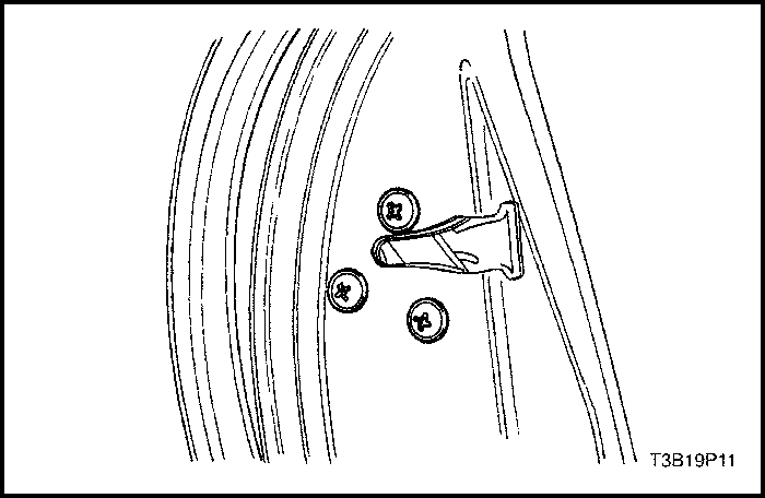
Door Lock Striker Screws
|
24
|
18
|
-
|
|
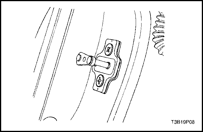
Door Pull Bracket Screws
|
3.5
|
-
|
31
|
|
Guide Rail Bolts
|
7
|
-
|
62
|
|
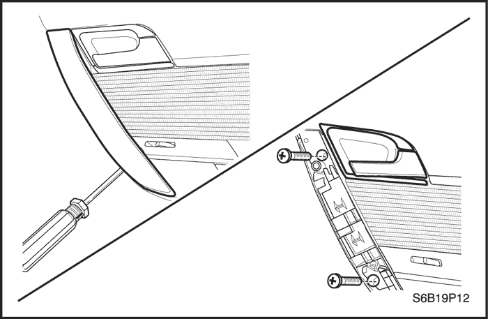
Inside Door Handle Screw
|
3
|
-
|
27
|
|
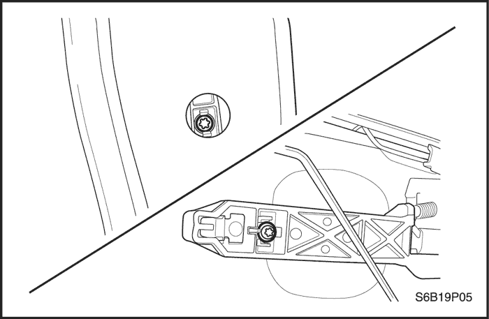
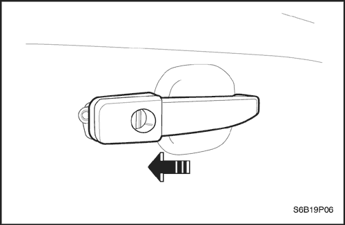
Outside Door Handle Bolts
|
4.5
|
-
|
40
|
|
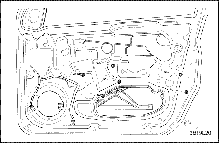
Window Regulator Nuts
|
7
|
-
|
62
|
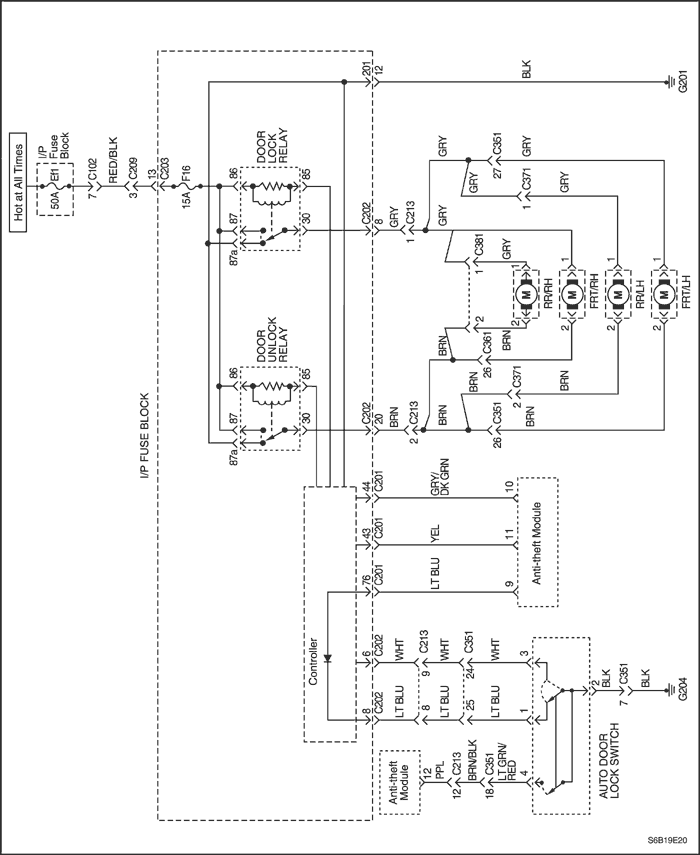
| Step | Action | Value(s) | Yes | No |
| 1 |
Is either window working?
|
-
|
Go to Step 18
|
Go to Step 2
|
| 2 |
Visually inspect the connection at the dual power window switch.
Is the electrical connector correctly attached to the switch?
|
-
|
Go to Step 4
|
Go to Step 3
|
| 3 |
Correctly attach the electrical connector to the dual power window switch.
Is the repair complete?
|
-
|
System OK
|
-
|
| 4 |
Is the voltage equal to the specified value?
|
11-14 v
|
Go to Step 16
|
Go to Step 5
|
| 5 |
Check fuses Ef2.
Is either fuse blown?
|
-
|
Go to Step 6
|
Go to Step 7
|
| 6 |
Is the repair complete?
|
-
|
System OK
|
-
|
| 7 |
Are both voltages equal to the specified value?
|
11-14 v
|
Go to Step 9
|
Go to Step 8
|
| 8 |
Repair the power supply to the fuse which did not indicate battery voltage with the ignition on.
Is the repair complete?
|
-
|
System OK
|
-
|
| 9 |
Does the voltmeter indicate the specified value at terminals 85 and 30?
|
11-14 v
|
Go to Step 11
|
Go to Step 10
|
| 10 |
Repair the open circuit between the fuses and the power window relay.
Is the repair complete?
|
-
|
System OK
|
-
|
| 11 |
With the power window relay still removed, use an ohmmeter to check the resistance between ground and terminal 87 of the power window relay socket.
Does the ohmmeter indicate the specified value?
|
≈ 0 Ω
|
Go to Step 13
|
Go to Step 12
|
| 12 |
Repair the open circuit between ground and terminal 86 of the power window relay socket.
Is the repair complete?
|
-
|
System OK
|
-
|
| 13 |
Do the power windows operate with the substituted relay?
|
-
|
Go to Step 14
|
Go to Step 15
|
| 14 |
Is the repair complete?
|
-
|
System OK
|
-
|
| 15 |
Repair the open circuit between the power window relay socket terminal 86 and the dual power window switch terminal 5.
Is the repair complete?
|
-
|
System OK
|
-
|
| 16 |
With the dual power window switch disconnected, use an ohmmeter to check the resistance between ground and terminal 8 of the dual power window switch connector.
Is the resistance equal to the specified value?
|
≈ 0 Ω
|
Go to Step 18
|
Go to Step 17
|
| 17 |
Repair the open circuit between ground and terminal 8 of the dual power window switch connector.
Is the repair complete?
|
-
|
System OK
|
-
|
| 18 |
Important : To prevent the fuse in the jumper wire from blowing, do not touch the jumper wires together.
Does the power window operate in both directions when the motor is operated directly from a battery?
|
-
|
Go to Step 20
|
Go to Step 19
|
| 19 |
Replace the window motor.
Is the repair complete?
|
-
|
System OK
|
-
|
| 20 |
Is the resistance at the switch connector approximately equal to the resistance that was previously measured at the motor connector?
|
-
|
Go to Step 22
|
Go to Step 21
|
| 21 |
Repair the open circuit between the window motor and the window switch.
Is the repair complete?
|
-
|
System OK
|
-
|
| 22 |
Replace the power window switch.
Is the repair complete?
|
-
|
System OK
|
-
|
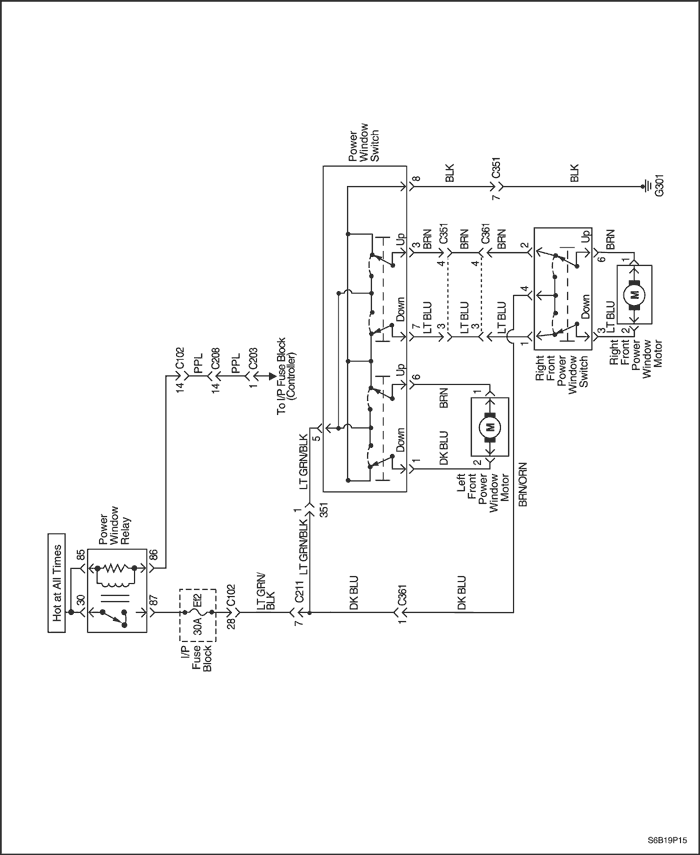
| Step | Action | Value(s) | Yes | No |
| 1 |
Is either window working?
|
-
|
Go to Step 18
|
Go to Step 2
|
| 2 |
Visually inspect the connection at the power window main switch.
Is the electrical connector correctly attached to the main switch?
|
-
|
Go to Step 4
|
Go to Step 3
|
| 3 |
Correctly attach the electrical connector to the power window main switch.
Is the repair complete?
|
-
|
System OK
|
-
|
| 4 |
Is the voltage equal to the specified value?
|
11-14 v
|
Go to Step 16
|
Go to Step 5
|
| 5 |
Check fuses Ef2.
Is either fuse blown?
|
-
|
Go to Step 6
|
Go to Step 7
|
| 6 |
Is the repair complete?
|
-
|
System OK
|
-
|
| 7 |
Are both voltages equal to the specified value?
|
11-14 v
|
Go to Step 9
|
Go to Step 8
|
| 8 |
Repair the power supply to the fuse which did not indicate battery voltage with the ignition on.
Is the repair complete?
|
-
|
System OK
|
-
|
| 9 |
Does the voltmeter indicate the specified value?
|
11-14 v
|
Go to Step 11
|
Go to Step 10
|
| 10 |
Repair the open circuit between the fuses and the power window relay.
Is the repair complete?
|
-
|
System OK
|
-
|
| 11 |
With the power window relay still removed, use an ohmmeter to check the resistance between ground and terminal 86 of the power window relay socket.
Does the ohmmeter indicate the specified value?
|
≈ 0 Ω
|
Go to Step 13
|
Go to Step 12
|
| 12 |
Repair the open circuit between ground and terminal 86 of the power window relay socket.
Is the repair complete?
|
-
|
System OK
|
-
|
| 13 |
Do the power windows operate with the substituted relay?
|
-
|
Go to Step 14
|
Go to Step 15
|
| 14 |
Is the repair complete?
|
-
|
System OK
|
-
|
| 15 |
Repair the open circuit between the power window relay socket terminal 87 and the power window switch terminal 13.
Is the repair complete?
|
-
|
System OK
|
-
|
| 16 |
With the power window main switch disconnected, use an ohmmeter to check the resistance between ground and terminal 8 of the power window switch connector.
Is the resistance equal to the specified value?
|
≈ 0 Ω
|
Go to Step 18
|
Go to Step 17
|
| 17 |
Repair the open circuit between ground and terminal 8 of the power window main switch connector.
Is the repair complete?
|
-
|
System OK
|
-
|
| 18 |
Does the power window operate in both directions when the motor is operated directly from a battery?
Important : To prevent the fuse in the jumper wire from blowing, do not touch the jumper wires together.
|
-
|
Go to Step 20
|
Go to Step 19
|
| 19 |
Replace the window motor.
Is the repair complete?
|
-
|
System OK
|
-
|
| 20 |
Is the resistance at the main switch connector approximately equal to the resistance that was previously measured at the motor connector?
|
-
|
Go to Step 22
|
Go to Step 21
|
| 21 |
Repair the open circuit between the window motor and the window switch.
Is the repair complete?
|
-
|
System OK
|
-
|
| 22 |
Replace the power window switch.
Is the repair complete?
|
-
|
System OK
|
-
|
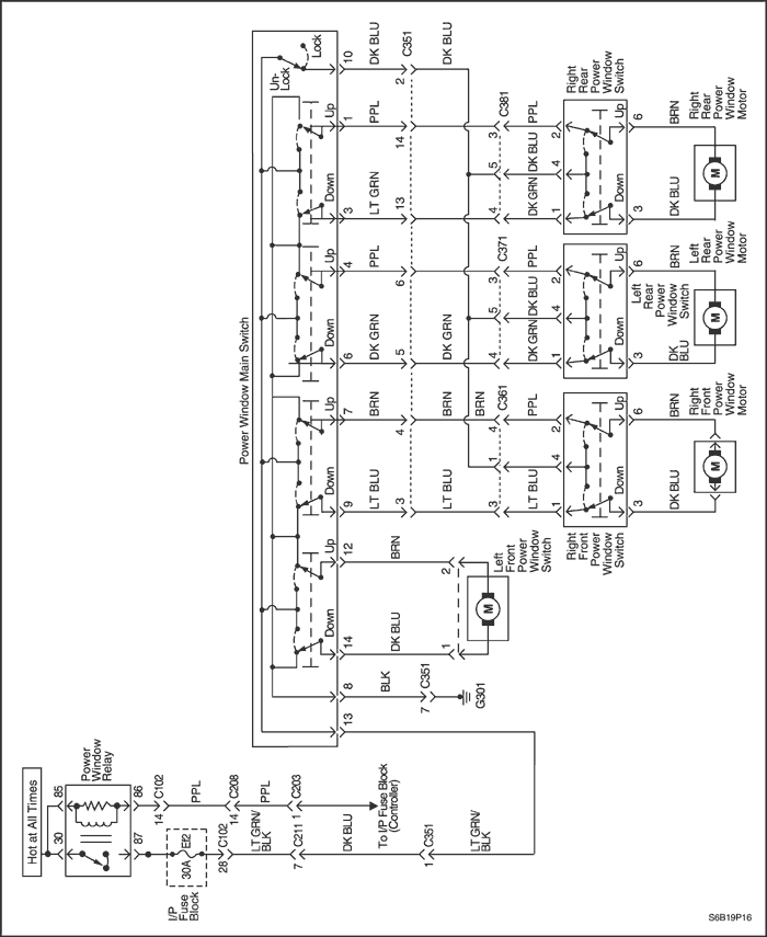
| Step | Action | Value(s) | Yes | No |
| 1 |
Is either rear power window working?
|
-
|
Go to Step 18
|
Go to Step 2
|
| 2 |
Visually inspect the connection at the power window main switch.
Is the electrical connector correctly attached to the main switch?
|
-
|
Go to Step 4
|
Go to Step 3
|
| 3 |
Correctly attach the electrical connector to the power window main switch.
Is the repair complete?
|
-
|
System OK
|
-
|
| 4 |
Is the voltage equal to the specified value?
|
11-14 v
|
Go to Step 16
|
Go to Step 5
|
| 5 |
Check fuses Ef2.
Is either fuse blown?
|
-
|
Go to Step 6
|
Go to Step 7
|
| 6 |
Is the repair complete?
|
-
|
System OK
|
-
|
| 7 |
Are both voltages equal to the specified value?
|
11-14 v
|
Go to Step 9
|
Go to Step 8
|
| 8 |
Repair the power supply to the fuse which did not indicate battery voltage with the ignition on.
Is the repair complete?
|
-
|
System OK
|
-
|
| 9 |
Does the voltmeter indicate the specified value?
|
11-14 v
|
Go to Step 11
|
Go to Step 10
|
| 10 |
Repair the open circuit between the fuses and the power window relay.
Is the repair complete?
|
-
|
System OK
|
-
|
| 11 |
With the power window relay still removed, use an ohmmeter to check the resistance between ground and terminal 86 of the power window relay socket.
Does the ohmmeter indicate the specified value?
|
≈ 0 Ω
|
Go to Step 13
|
Go to Step 12
|
| 12 |
Repair the open circuit between ground and terminal 86 of the power window relay socket.
Is the repair complete?
|
-
|
System OK
|
-
|
| 13 |
Do the power windows operate with the substituted relay?
|
-
|
Go to Step 14
|
Go to Step 15
|
| 14 |
Is the repair complete?
|
-
|
System OK
|
-
|
| 15 |
Repair the open circuit between the power window relay socket terminal 87 and the power window main switch terminal 13.
Is the repair complete?
|
-
|
System OK
|
-
|
| 16 |
With the power window main switch disconnected, use an ohmmeter to check the resistance between ground and terminal 8 of the power window main switch connector.
Is the resistance equal to the specified value?
|
≈ 0 Ω
|
Go to Step 18
|
Go to Step 17
|
| 17 |
Repair the open circuit between ground and terminal 8 of the power window switch connector.
Is the repair complete?
|
-
|
System OK
|
-
|
| 18 |
Does the power window operate in both directions when the motor is operated directly from a battery?
Important : To prevent the fuse in the jumper wire from blowing, do not touch the jumper wires together.
|
-
|
Go to Step 20
|
Go to Step 19
|
| 19 |
Replace the power window motor.
Is the repair complete?
|
-
|
System OK
|
-
|
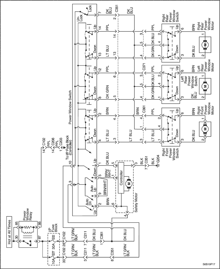
| 20 |
Is the voltage equal to the specified value?
|
11-14v
|
Go to Step 21
|
Go to Step 29
|
| 21 |
Is the resistance measured at the rear power window switch connector equal to the resistance previously measured at the rear power window motor connector?
|
-
|
Go to Step 23
|
Go to Step 22
|
| 22 |
Repair the open circuit between the rear power window switch and the rear power window motor connector.
Is the repair complete?
|
-
|
System OK
|
-
|
| 23 |
For both tests, did the ohmmeter indicate the specified value?
|
≈ 0 Ω
|
Go to Step 25
|
Go to Step 24
|
| 24 |
Replace the rear power window switch.
Is the repair complete?
|
-
|
System OK
|
-
|
| 25 |
For both tests, did the ohmmeter indicate the specified value?
|
≈ 0 Ω
|
Go to Step 26
|
Go to Step 24
|
| 26 |
Is the resistance equal to the resistance previously measured at the motor connector?
|
-
|
Go to Step 28
|
Go to Step 27
|
| 27 |
Repair the open circuit between the power window main switch and the rear power window switch.
Is the repair complete?
|
-
|
System OK
|
-
|
| 28 |
Replace the power window main switch.
Is the repair complete?
|
-
|
System OK
|
-
|
| 29 |
Is the voltage equal to the specified value?
|
11-14 v
|
Go to Step 27
|
Go to Step 28
|

| © Copyright Chevrolet Europe. All rights reserved |


