To the top of the document
Spark
   
GMDE Start Page Load static TOC Load dynamic TOC Help?

Engine Replacement - with EN-49802 and EN-50176

Special Tools

    • EN-48244 Engine Assembly Remove/Install Pallet Support
    • EN-49271 Engine Stand
    • EN-49802 Cradle Support
    • EN-50176 Powertrain Support Pallet
    • EN-50177 Cradle Support Holder
    • KM-490-B Angular Torque Gauge

For equivalent regional tools, refer to Special Tools .

Removal Procedure

Note: The front wheels of the vehicle must be maintained in the straight ahead position and the steering column must be in the LOCK position before disconnecting the steering column or intermediate shaft. Failure to follow these procedures will cause incorrect alignment of some components during installation and result in damage to the SIR coil assembly.

  1. Turn the ignition key to the LOCK position.
  2. Warning: Refer to Battery Disconnect Warning in the Preface section.

  3. Open the bonnet.
  4. Depressurise the fuel system. Refer to Fuel Pressure Relief .
  5. Disconnect the battery negative cable. Refer to Battery Negative Cable Disconnection and Connection .
  6. Recover the air conditioning (A/C) refrigerant. Refer to Refrigerant Recovery and Recharging .
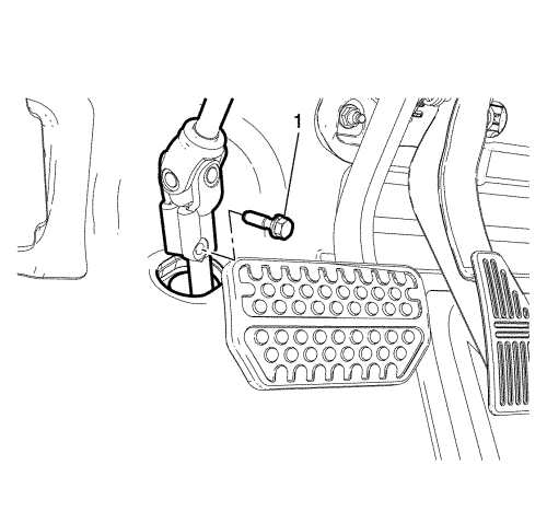
  7. 2308813
  8. Remove the lower intermediate steering shaft bolt (1).
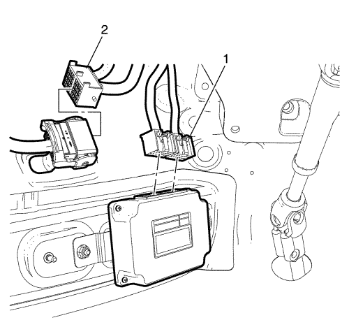
  9. 2308783
  10. Disconnect TCM connectors (1) and engine wiring harness (2).
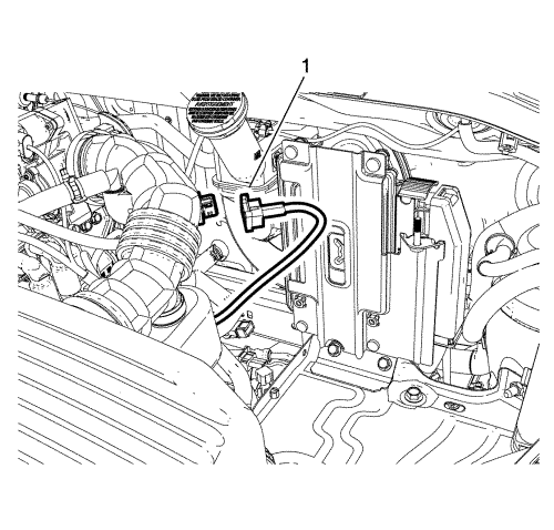
  11. 2308784
  12. Disconnect intake air temperature sensor connector (1).
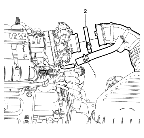
  13. 2308324
  14. Remove the clamps (1, 2).
  15. Twist and pull the hoses to remove throttle body assembly.
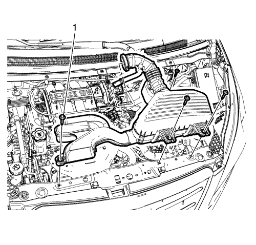
  16. 2308785
  17. Remove the 4 air cleaner assembly bolts (1).
  18. Remove the air cleaner assembly.

  19. 2308321
  20. Disconnect the accelerator cable, if equipped.
  21. Remove the battery. Refer to Battery Replacement .
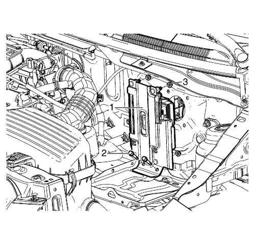
  22. 2308927
  23. Remove the engine control module (ECM) bracket to battery tray retaining bolts (2).
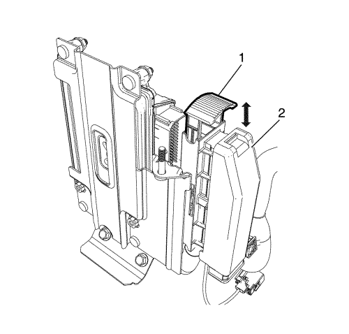
  24. 2308831
  25. Pull the engine control module (ECM) electrical connector lever (1) and disconnect the engine control module (ECM) electrical connector (2).
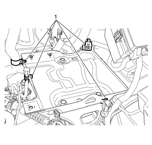
  26. 2308832
  27. Remove the retainers (1) from the battery tray with a suitable tool.
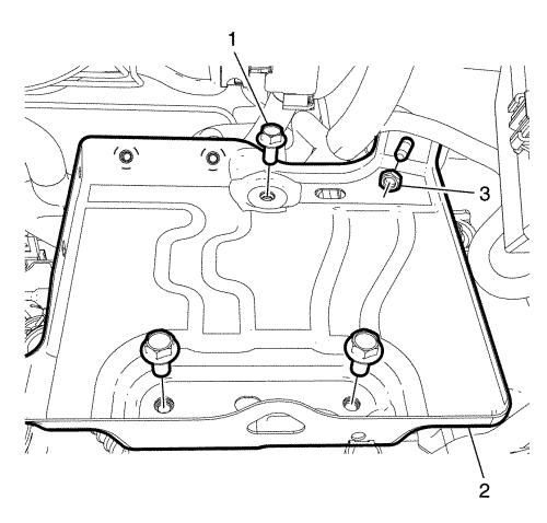
  28. 2308833
  29. Remove the bolts (1) and nut (3).
  30. Remove the battery tray (2)

  31. 2308786
  32. Remove the under hood body electrical centre (BEC) cover.
  33. 2308787
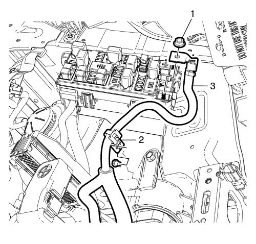
  34. Remove the positive cable to body electrical centre (BEC) retaining nut (1).
  35. Pull back the positive cable (3) to separate the positive cable retainer (2) from body.
  36. 2308790
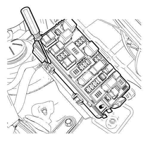
  37. Raise the upper plate with suitable tool.
  38. 2308791
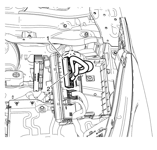
  39. Remove the under hood BEC upper plate to lower plate retaining bolts (2).
  40. Disconnect the wiring harness plug (1) from the front compartment fuse block.
  41. 2308792
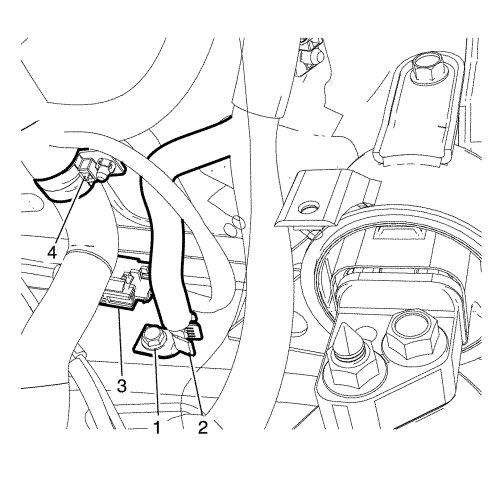
  42. Remove the ground bolt (1) and put the wiring harness (2) aside.
  43. Disconnect the wheel speed sensor connector (3).
  44. Move the wiring harness retainer (4) aside with suitable tool.
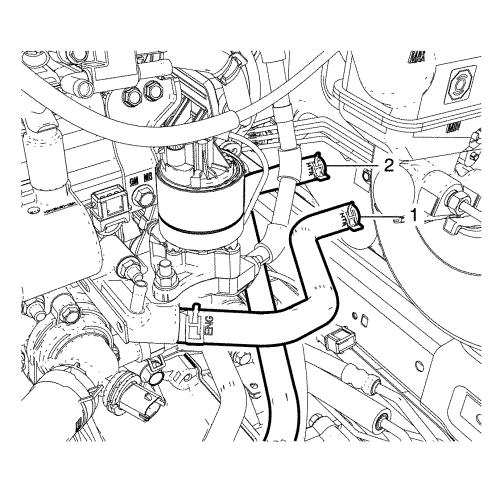
  45. 2308794
  46. Disconnect the heater inlet hose (1) and outlet hose (2) from the heater pipe.
  47. Note: Plug or cap the hoses and inlets when separating the cooling system components, this prevents dirt and other contaminants from entering the cooling system.

  48. Plug or cap the cooling system hoses and inlets.
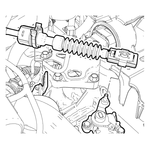
  49. 2308788
  50. Disconnect the transmission range selector lever cable terminal from the transmission lever pin. For manual gearbox refer to Manual Gearbox Gear Lever and Selector Lever Cable Replacement .
  51. Press the locking tabs inward in order to release the transmission range selector lever cable from the cable bracket.
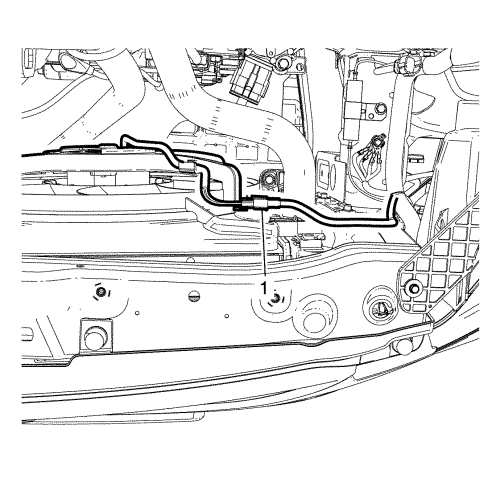
  52. 2308793
  53. Disconnect the pan module connector (1).
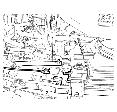
  54. 2308834
  55. Disconnect the ambient air temperature sensor connector (2) if equipped.
  56. Note: Plug or cap the hoses and inlets when separating the cooling system components, this prevents dirt and other contaminants from entering the cooling system.

  57. Disconnect the coolant hose (1) from the CRFM.
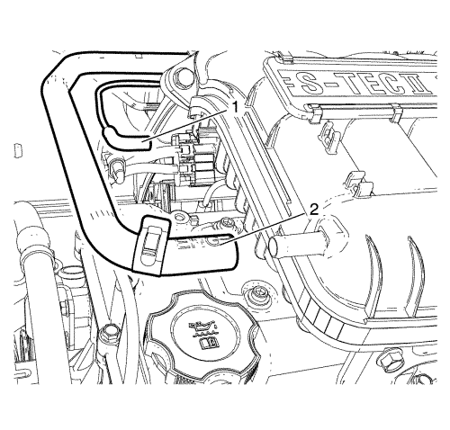
  58. 2308768

    Note: With the ignition OFF and the brakes cool, apply the brakes 3-5 times, or until the brake pedal becomes firm, in order to deplete the vacuum brake booster power reserve.

  59. Deplete the vacuum brake booster power reserve.
  60. Disconnect the vacuum hose (2) from upper intake manifold.
  61. Reposition and retain the vacuum hose (2) away from the powertrain.
  62. Raise the vehicle. Refer to Lifting and Jacking the Vehicle .
  63. Remove the front wheels. Refer to Tyre and Wheel Removal and Installation .
  64. Remove the front bumper fascia. Refer to Front Bumper Fascia Replacement .
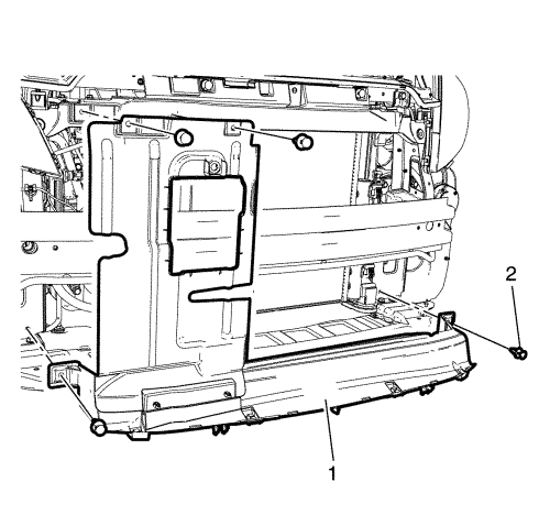
  65. 2308799
  66. Remove the clips (2).
  67. Remove the front air guard (1).

  68. 2308795
  69. Remove the cover (1, 2).

  70. 2308836
  71. Remove the clip (2) and the water deflector (1).
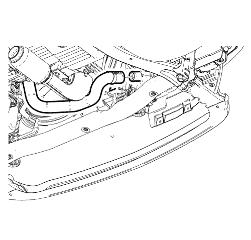
  72. 2308801
  73. Place a suitable container beneath the radiator and engine.
  74. Note: Plug or cap the hoses and inlets when separating the cooling system components, this prevents dirt and other contaminants from entering the cooling system.

  75. Drain the cooling system by disconnecting lower coolant hose as shown.
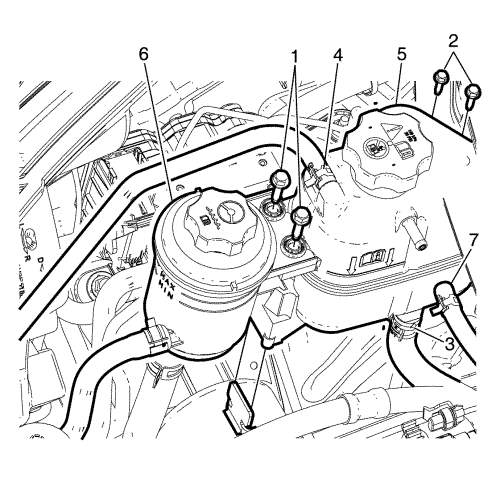
  76. 2308800

    Note: DO not remove power steering fluid hose from power steering fluid reservoir.

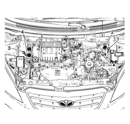
  77. Remove power steering fluid reservoir bolts (1) and unclip the power steering fluid reservoir and retain it on the engine.
  78. Disconnect the coolant hoses (3, 4, 7) from the coolant surge tank.
  79. Note: Plug or cap the hoses and inlets when separating the cooling system components, this prevents dirt and other contaminants from entering the cooling system.

  80. Plug or cap the cooling system hoses and inlets.
  81. Remove the coolant surge tank to body retaining bolts (2).
  82. Remove the coolant surge tank.

  83. 2308805
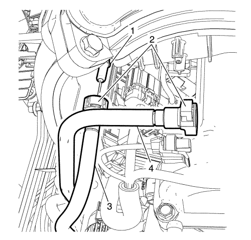
  84. Disconnect the fuel feed hose (3) from the fuel feed pipe (1).
  85. Note: Plug or cap the fuel feed pipe (1) and fuel feed hose (3) ends to prevent fuel leaks and/or contamination.

  86. Plug or cap the fuel feed pipe (1) and fuel feed hose (3) ends.
  87. Disconnect the evaporative emission (EVAP) purge line (4) from the purge solenoid.
  88. Note: When removal is complete plug hose openings with a clean lint free cloth to prevent foreign matter entry.

  89. Plug or cap the (EVAP) purge line (4) and the purge solenoid ends.
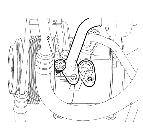
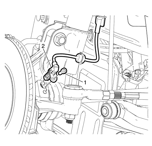
  90. 2308804
  91. Remove the suction/discharge line pad to A/C compressor retaining bolt (2).
  92. Disconnect the A/C suction/discharge line pad from the A/C compressor.
  93. Note: Plug or cap the A/C suction/discharge pipe ends and the compressor ports immediately to prevent contamination and absorption of moisture from the atmosphere.

  94. Plug or cap the A/C suction/discharge pipe ends and the compressor ports.
  95. Note: The A/C sealing O-rings are a single use component and will not reseal. Install NEW A/C sealing O-rings whenever the A/C suction/discharge line pad is removed from the A/C compressor.

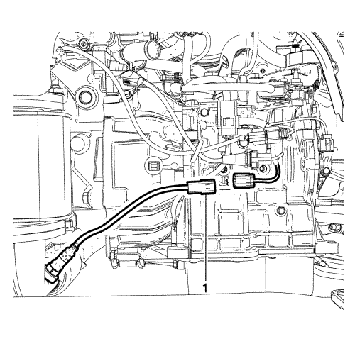
  96. Remove and discard the A/C suction/discharge pipe sealing O-rings.
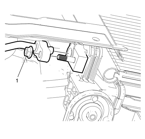
  97. 2308803

    Note: Plug or cap the A/C suction/discharge pipe ends and the compressor ports immediately to prevent contamination and absorption of moisture from the atmosphere.

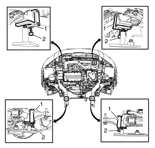
  98. Remove A/C compressor and condenser hose nut (1) from A/C condenser.
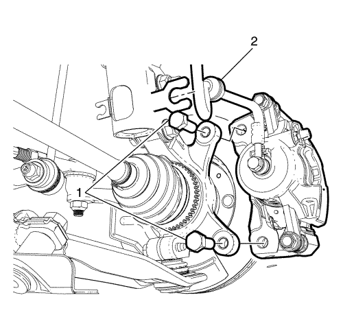
  99. 2308796

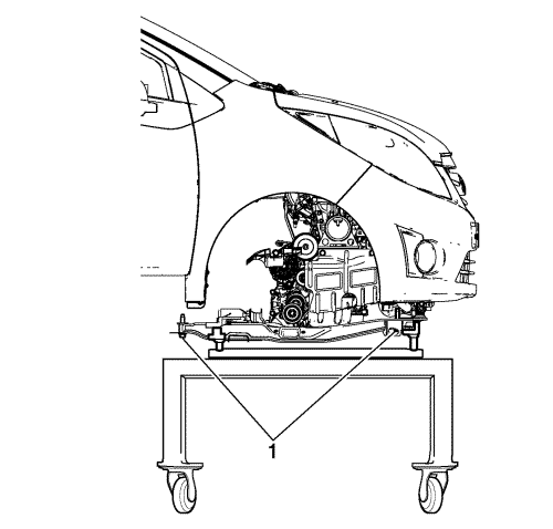
    Note: DO NOT disconnect the hydraulic brake flexible hose from the brake calliper otherwise complete bleeding of the braking system will be necessary.

  100. Detach the front brake hose (2) from the strut mounted brake hose retaining bracket and remove the front brake calliper anchor plate to knuckle retaining bolts (1). Repeat for opposite side.
  101. Remove the front brake calliper from the front steering knuckle. Repeat for opposite side.
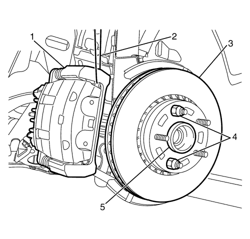
  102. 1943453

    Caution: Support the brake calliper with heavy mechanic wire, or equivalent, whenever it is separated from its mount and the hydraulic flexible brake hose is still connected. Failure to support the calliper in this manner will cause the flexible brake hose to bear the weight of the calliper, which may cause damage to the brake hose and in turn may cause a brake fluid leak.

  103. Support the front brake calliper (1) with heavy mechanic's wire, or equivalent (2). Repeat for opposite side.
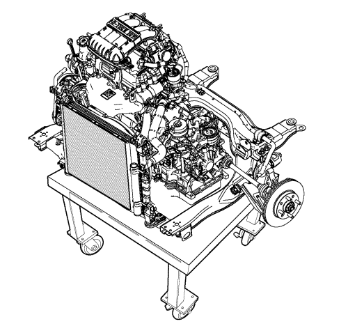
  104. 2308797
  105. Remove the wheel speed sensor retaining bolt (1) and detach wheel speed sensor harness (2) from the strut mounted retaining bracket.
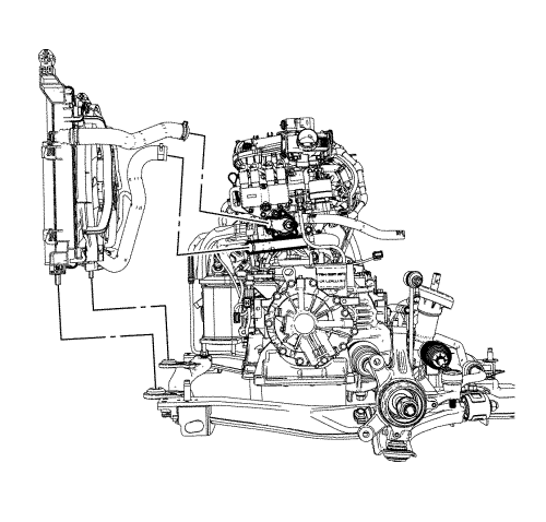
  106. Secure away from the cradle and suspension components. Repeat for opposite side.

  107. 2519299
  108. Remove the bolts (3) and nuts (1, 4).
  109. Remove the stabiliser shaft link (2) from the strut mounted retaining bracket. Repeat for opposite side.
  110. 2308789
  111. Disconnect the oxygen sensor connector (1).
  112. Remove the exhaust flexible pipe. Refer to Exhaust Pipe Replacement .
  113. 2327673
  114. Install the EN-50176 powertrain support pallet, EN-49802 cradle support, and EN-50177 cradle support holder . Refer to Engine/Transmission Mounting : with CH-49289 and CH-49290 → with EN-49802 and EN-50176 .
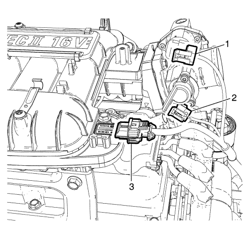
  115. 2328260
  116. Position the EN-48244 engine assembly remove/install pallet support or suitable powertrain and/or engine lift table below the frame as shown.
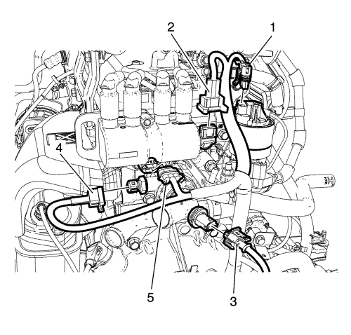
  117. Lower the vehicle until the EN-49802 cradle support contacts the EN-48244 engine assembly remove/install pallet support or suitable powertrain and/or engine lift table.
  118. Remove the 4 cradle bolts (1).

  119. 2308302
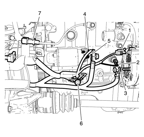
  120. Remove the engine mount retaining bolt (3) and nuts (4).
  121. Remove the transmission retaining bolt (1) and nut (2).
  122. 2308309

    Note: Make sure that all the hoses, wires, pipes and front struts clear the vehicle during the removal process.

  123. With the aid of an assistant, lower the table and/or raise the vehicle to remove the engine, transmission, and cradle assembly from the vehicle.
  124. 2327659
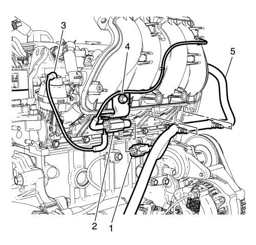
  125. Remove the suction/charge line pad to A/C compressor retaining bolt and suction/charge line pad to condenser retaining nut.
  126. Disconnect the A/C suction/charge line pad from the A/C compressor.
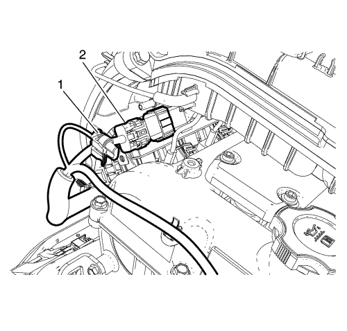
  127. Note: Plug or cap the A/C suction/discharge pipe ends and the compressor ports immediately to prevent contamination and absorption of moisture from the atmosphere.

  128. Plug or cap the A/C suction/charge pipe ends, condenser ports and the compressor ports.
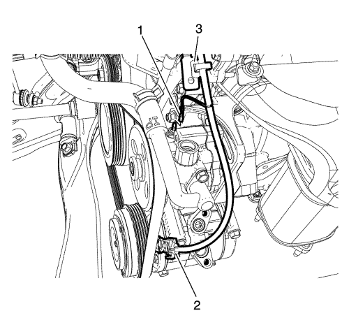
  129. Note: The A/C sealing O-rings are a single use component and will not reseal. Install NEW A/C sealing O-rings whenever the A/C suction/discharge line pad is removed from the A/C compressor.

  130. Remove and discard the A/C suction/charge pipe sealing O-rings.
  131. Discard the O-rings.
  132. Remove the condenser radiator fan module (CRFM).
  133. 2308328
  134. Disconnect the idle air control valve (IACV) connector (1), throttle position sensor (TPS) connector (2), manifold absolute pressure (MAP) sensor connector (3).
  135. 2327657
  136. Disconnect the EGR connector (1), camshaft position sensor connector (2), thermostat heater connector (3), engine coolant temperature sensor connector (4) and DIS connector (5).
  137. 2327654
  138. Disconnect the alternator harness connector (1), oil pressure switch connector (2) and knock sensor connector (7).
  139. Remove the battery positive cable to alternator retaining nut.
  140. Disconnect the battery positive cable (3) from the alternator.
  141. Remove the battery cable harness to starter motor retaining nut.
  142. Disconnect the battery cable harness (4, 5) from the starter motor.
  143. Remove the engine wiring harness ground to cylinder block retaining bolt (6).
  144. 2308821
  145. Disconnect the intake manifold runner control valve connector (1) and detach the wiring harness (5) from intake manifold.
  146. 2327645
  147. Disconnect the canister purge solenoid connector (1) and the injector harness electrical connector (2).
  148. 2327646
  149. Disconnect the power steering connector (1), and A/C compressor electrical connector (2).
  150. Detach the engine wiring harness clip (3) from the bracket.
  151. Remove the engine wiring harness from the powertrain.
  152. Remove the power steering belt. Refer to Power Steering Pump Belt Removal .
  153. Remove the drive belt. Refer to Drive Belt Removal .
  154. Remove the power steering pump. Refer to Power Steering Pump Replacement .
  155. Remove the A/C compressor. Refer to Air Conditioning Compressor Replacement .
  156. Remove the alternator. Refer to Generator Replacement .
  157. Loosen the transmission bolts and remove. Refer to Transmission Replacement for the Y4M transmission and Transmission Replacement for the Jatco transmission.
  158. Attach a suitable lifting chain and hooks to lift bracket.
  159. Using a suitable lifting crane, raise the engine.
  160. Install the engine to the EN-49271 engine stand as needed.
  161. Transfer parts as needed.

Installation Procedure

  1. Attach a suitable lifting chain and hooks to lift bracket.
  2. Using a suitable lifting crane, raise the engine.
  3. Install the engine to the transmission and cradle.
  4. Install the transmission bolts. Refer to Transmission Replacement for the Y4M transmission and Transmission Replacement for the Jatco transmission.
  5. Install the alternator. Refer to Generator Replacement .
  6. Install the A/C compressor. Refer to Air Conditioning Compressor Replacement .
  7. Install the power steering pump. Refer to Power Steering Pump Replacement .
  8. Install the drive belt. Refer to Drive Belt Tensioner Installation .
  9. Install the power steering belt. Refer to Power Steering Pump Belt Installation .

  10. 2327645
  11. Install the engine wiring harness to the powertrain.
  12. Attach the engine wiring harness clip to the bracket.
  13. Connect the power steering connector (1), and A/C compressor electrical connector.

  14. 2327646
  15. Connect the canister purge solenoid connector (1) and the injector harness electrical connector (2).

  16. 2308821
  17. Connect the intake manifold runner control valve connector (1) and attach the wiring harness (5) to the intake manifold.

  18. 2327654
  19. Connect the alternator harness connector (1), oil pressure switch connector (2), and knock sensor connector (7).
  20. Install the battery cable harness (4, 5) to the starter motor.
  21. Caution: Refer to Fastener Caution in the Preface section.

  22. Tighten the battery cable harness (5) to starter motor retaining nut to 10 N·m (89 lb in).
  23. Tighten the battery cable harness (4) to starter motor retaining nut to 5.5 N·m (49 lb in).
  24. Install the engine wiring harness ground to cylinder block and tighten the bolt (6) to 50 N·m (37 lb ft).

  25. 2327657
  26. Connect the EGR connector (1), camshaft position sensor connector (2), thermostat heater connector (3), engine coolant temperature sensor connector (4), and DIS connector (5).

  27. 2308328
  28. Connect the idle air control valve (IACV) connector (1), throttle position sensor (TPS) connector (2), manifold absolute pressure (MAP) sensor connector (3).

  29. 2327659
  30. Install the condenser radiator fan module (CRFM).

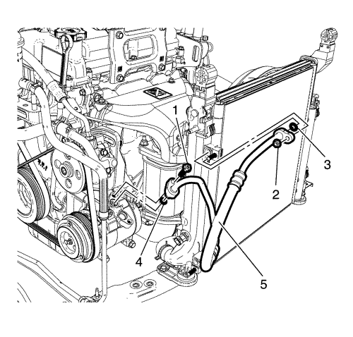
  31. 2327661
  32. Install the new O-rings (3, 4).
  33. Remove the plug or cap from the A/C suction/charge pipe ends, condenser ports and the compressor ports.
  34. Connect the A/C suction/charge line (5) to the A/C compressor.
  35. Tighten the suction/charge line pad to A/C compressor retaining bolt (1) to 22 N·m (16 lb ft).
  36. Tighten the suction/charge line pad to condenser retaining nut (2) to 10 N·m (89 lb in).

  37. 2308309
  38. With the aid of an assistant, raise the table and/or lower the vehicle to install the engine, transmission, and cradle assembly to the vehicle.

  39. 2308302
  40. Install the transmission retaining bolt (1) and nut (2).
  41. Install the engine mount retaining bolt (3) and nuts (4).
  42. Tighten the transmission retaining bolt (1) and nut (2) to 75 N·m (55 lb ft).
  43. Tighten the engine mount retaining bolt (3) and nuts (4) to 58 N·m (43 lb ft).

  44. 2328260
  45. Tighten the 4 cradle bolts (1) to 170 N·m (125 lb ft).
  46. Remove the EN-48244 engine assembly remove/install pallet support or suitable powertrain and/or engine lift table.

  47. 2327673
  48. Remove the EN-50176 powertrain support pallet, EN-49802 cradle support, and EN-50177 cradle support holder . Refer to Engine/Transmission Mounting : with CH-49289 and CH-49290 → with EN-49802 and EN-50176 .
  49. Install the exhaust flexible pipe. Refer to Exhaust Pipe Replacement .

  50. 2308789
  51. Connect the oxygen sensor connector (1).

  52. 2519299
  53. Install the stabiliser shaft link (2) to the strut mounted retaining bracket.
  54. Install the bolts (3) and nuts (4).
  55. Tighten the bolts (3) and nuts (4) to 100 N·m (74 lb ft).
  56. Tighten the nut (1) to 43 N·m (32 lb ft).

  57. 2308797
  58. Install the wheel speed sensor and attach wheel speed sensor harness (2) to the strut mounted retaining bracket and tighten the bolt (1) to 8.5 N·m (75 lb in).

  59. 1943453

    Caution: Make sure the brake hose is not twisted or kinked after installation. Damage to the hose could result.

  60. Remove the heavy mechanic's wire, or equivalent support (2) from the brake calliper (1).
  61. Install the brake calliper assembly (1) to the steering knuckle (3).

  62. 2308796

    Caution: Make sure the brake hose is not twisted or kinked after installation. Damage to the hose could result.

  63. Tighten the brake calliper anchor plate to knuckle retaining bolts (1) to 95 N·m (70 lb ft).
  64. Attach the brake hose (2) to the strut mounted brake hose retaining bracket. Repeat for opposite side.

  65. 2308803
  66. Remove the plug or cap from A/C suction/discharge pipe ends and the compressor ports.
  67. Note: DO NOT coat the new sealing washer with oil. They must be fitted dry. The use of mineral oil will render the washer useless, as the washer WILL swell causing refrigerant to leak out.

  68. Install the new O-ring.
  69. Install A/C compressor and condenser hose to A/C condenser and tighten the nut (1) to 10 N·m (89 lb in).

  70. 2308804
  71. Remove the plug or cap from the A/C suction/discharge pipe ends and the compressor ports.
  72. Note: The A/C sealing O-rings must be fitted dry. DO NOT lubricate the A/C sealing O-rings.

  73. Fit the NEW A/C suction/discharge pipe sealing O-ring to the suction pipe.
  74. Connect the A/C suction/discharge line pad to the A/C compressor.
  75. Tighten the suction/discharge line pad to A/C compressor retaining bolt (2) to 22 N·m (16 lb ft).

  76. 2308805
  77. Remove the plug or cap from the (EVAP) purge line (4) and the purge solenoid ends.
  78. Connect the evaporative emission (EVAP) purge line (4) to the purge solenoid.
  79. Remove the plug or cap from the fuel feed pipe (1) and fuel feed hose (3) ends.
  80. Connect the fuel feed hose (3) to the fuel feed pipe (1).

  81. 2308800
  82. Install the coolant surge tank (5) to the bracket mounted on the engine mount.
  83. Tighten the coolant surge tank to body retaining bolts (2) to 9 N·m (80 lb in).
  84. Remove the plug or cap from the cooling system hoses and inlets.
  85. Connect the coolant hoses (3, 4, 7) to the coolant surge tank.
  86. Install the power steering fluid reservoir to the coolant surge tank.
  87. Tighten the power steering fluid reservoir bolts (1) to 9 N·m (80 lb in).

  88. 2308801
  89. Connect the lower coolant hose as shown.

  90. 2308836
  91. Install the water deflector (1) and the clip (2).

  92. 2308795
  93. Install the cover (1, 2).

  94. 2308799
  95. Install the front air guard (1) and clips (2).
  96. Install the front bumper fascia. Refer to Front Bumper Fascia Replacement .
  97. Install the front wheels. Refer to Tyre and Wheel Removal and Installation .
  98. Lower the vehicle. Refer to Lifting and Jacking the Vehicle .

  99. 2308768
  100. Connect the vacuum hose (2) to upper intake manifold.

  101. 2308834
  102. Remove the plug or cap from the hoses and inlets.
  103. Connect the coolant hose (1) to the CRFM.
  104. Connect the ambient air temperature sensor connector (2) if equipped.

  105. 2308793
  106. Connect the pan module connector (1).

  107. 2308788
  108. Install the transmission range selector lever cable to the cable bracket.
  109. Connect the transmission range selector lever cable terminal to the transmission lever pin. For manual gearbox refer to Manual Gearbox Gear Lever and Selector Lever Cable Replacement .
  110. Check the range selector cable adjustment. Refer to Range Selector Lever Cable Adjustment .

  111. 2308794
  112. Remove the plug or cap from the cooling system hoses and inlets.
  113. Connect the heater inlet hose (1) and outlet hose (2) to the heater pipe.

  114. 2308792
  115. Install the wiring harness retainer (4).
  116. Connect the wheel speed sensor (3).
  117. Install the ground wiring harness (2) and tighten the bolt (1) to 10 N·m (89 lb in).

  118. 2308791
  119. Connect the wiring harness plug (1) to the front compartment fuse block.
  120. Tighten the under hood BEC upper plate to lower plate retaining bolts (2) to 6 N·m (53 lb in).
  121. Install the upper plate.

  122. 2308787
  123. Install the positive cable to the positive cable retainer (2) to body.
  124. Tighten the positive cable to body electrical centre (BEC) retaining nut (1) to 10 N·m (89 lb in).

  125. 2308786
  126. Install the under hood body electrical centre (BEC) cover.

  127. 2308833
  128. Install the battery tray (2) and tighten the bolts (1) and nut (3) to 11.5 N·m (102 lb in).

  129. 2308832
  130. Install the retainers (1) to the battery tray.

  131. 2308831
  132. Push the engine control module (ECM) electrical connector lever (1) while pushing engine control module (ECM) electrical connector (2) to engine control module (ECM).

  133. 2308927
  134. Tighten the engine control module (ECM) bracket to battery tray retaining bolts (2) to 10 N·m (89 lb in).
  135. Install the battery. Refer Battery Replacement .

  136. 2308321
  137. Connect the accelerator cable, if equipped.

  138. 2308785
  139. Install the air cleaner assembly and tighten the 4 air cleaner assembly bolts (1) to 6 N·m (53 lb in).

  140. 2308324
  141. Install the hoses to throttle body assembly.
  142. Tighten the clamp (2).

  143. 2308784
  144. Connect intake air temperature sensor connector (1).

  145. 2308783
  146. Connect the TCM connectors (1) and engine wiring harness (2).

  147. 2308813
  148. Install the lower intermediate steering shaft. Refer to Intermediate Steering Shaft Replacement .
  149. Tighten the bolt (1) to 25 N·m (18 lb ft).
  150. Evacuate and recharge the A/C system. Refer to Refrigerant Recovery and Recharging .
  151. Refill the cooling system. Refer to Cooling System Draining and Filling .
  152. Check the oil level and fill NEW engine oil up if necessary.
  153. Connect the battery negative cable. Refer to Battery Negative Cable Disconnection and Connection .
  154. Close the bonnet.


© Copyright Chevrolet. All rights reserved