Engine Front Cover with Oil Pump Replacement - with CH-49290
Special Tools
| • | CH-49290 Engine Support Tool |
For equivalent regional tools, refer to Special Tools .
Removal Procedure
- Open the bonnet.
Warning: Refer to Battery Disconnect Warning in the Preface section.
- Disconnect the negative battery cable.
- Drain the cooling system. Refer to Cooling System Draining and Filling .
- Remove the upper intake manifold. Refer to Upper Intake Manifold Replacement .
- Remove the camshaft cover. Refer to Camshaft Cover Replacement .
- Remove the oil dipstick and tube. Refer to Oil Level Indicator Tube Replacement .
- Raise the vehicle by its full height. Refer to Lifting and Jacking the Vehicle .
- Remove the sump. Refer to Sump Replacement .
- Remove the drive belt. Refer to Drive Belt Replacement .
- Remove the water pump. Refer to Water Pump Replacement .
- Remove the crankshaft balancer. Refer to Crankshaft Balancer Removal .
- Remove the generator. Refer to Generator Replacement .
- Remove the drive belt tensioner. Refer to Drive Belt Tensioner Removal .
Note: The SPX installation manual is supplied with the special tool and is also available online from SPX directly. Go to www.spxtools-shop.com.
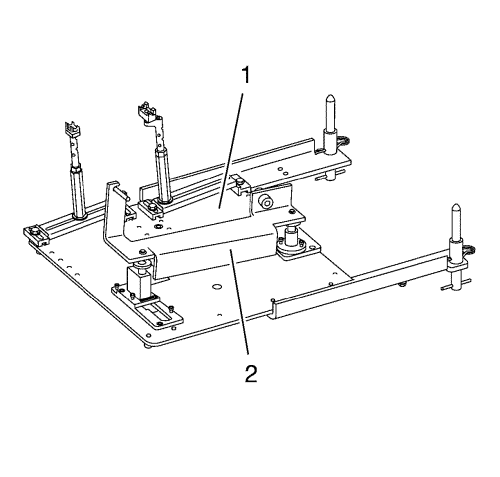
- Assemble the CH-49290 engine support tool (1) according to the details provided in the SPX installation manual.
- Install the torque support (2) to the engine.
- Support the CH-904 base frame on a jack.
- Support the CH-49290 engine support tool on the CH-904 base frame .
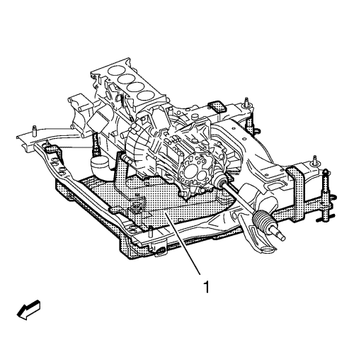
Note: The SPX installation manual is supplied with the special tool and is also available online from SPX directly.
- Install the CH-49290 engine support tool (1) according to the details provided in the SPX installation manual.
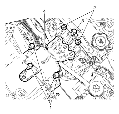
- Remove the engine mount bolts (1, 3) and nuts (2).
- Remove the engine mount (4).
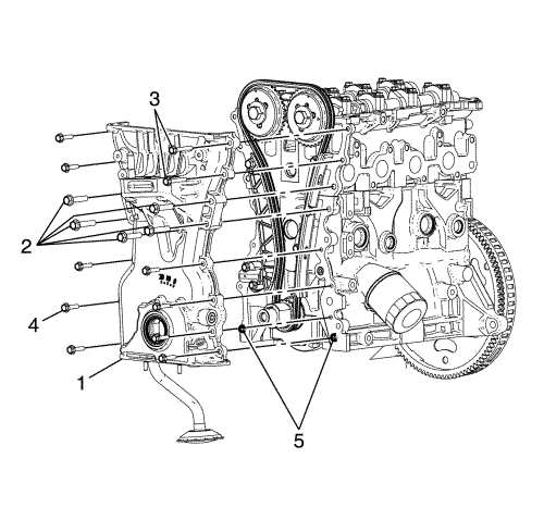
- Remove the engine front cover bolts (2, 3, 4).
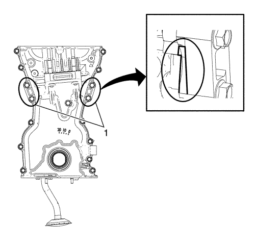
Note: Use the pry points and a bolt in the jackscrew hole in order to remove the engine front cover.
- Using the pry points (1) located at the edge of the front cover, shear the room temperature vulcanising (RTV) sealant.
- Remove the engine front cover evenly all the way around with a suitable tool. Refer to Engine Front Cover and Oil Pump Removal .
Note: There are no serviceable components within the oil pump. Disassemble the pump only to diagnose an oiling concern. A disassembled oil pump must not be reused. A disassembled oil pump must be replaced.
- Disassemble the engine front cover as necessary. Refer to Oil Pump Disassemble .
Installation Procedure
Note: DO NOT use sharp and/or metal gasket scrapers in order to clean the sealing surfaces.
- Carefully clean the engine front cover sealing surfaces.
- Assemble the engine front cover as necessary. Refer to Oil Pump Assemble .
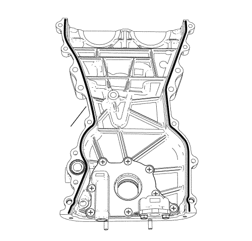
- Apply an approximately 3.5 mm (0.14 in) thick bead of oil pan sealant
- Install the engine front cover.
Note: Do not damage the sealing surfaces.
- Install the engine front cover with the included oil pump (1).
Caution: Refer to Fastener Caution in the Preface section.
Note: Check the different screw lengths.
- Tighten the bolts (2, 3, 4) to 20 N·m (15 lb ft).
- Install the engine mount (4).
- Install the bolts (1, 3) and nuts (2).
- Tighten the engine mount to body retaining bolts (1) to 50 N·m (37 lb ft).
- Tighten the engine mount to engine retaining bolt (3) and nuts (2) to 58 N·m (43 lb ft).
- Remove the CH-49290 engine support tool (1).
- Remove the CH-49290 engine support tool from the CH-904 base frame .
- Remove the CH-904 base frame from the jack.
- Disassemble the CH-49290 engine support tool (1).
- Remove the torque support (2) from the engine.
- Install the drive belt tensioner. Refer to Drive Belt Tensioner Installation .
- Install the generator. Refer to Generator Replacement .
- Install the crankshaft balancer. Refer to Crankshaft Balancer Installation .
- Install the water pump. Refer to Water Pump Replacement .
- Install the drive belt. Refer to Drive Belt Replacement .
- Install the oil pan. Refer to Sump Replacement .
- Lower the vehicle. Refer to Lifting and Jacking the Vehicle .
- Install the engine oil dipstick and tube. Refer to Oil Level Indicator Tube Replacement .
- Install the camshaft cover. Refer to Camshaft Cover Replacement .
- Install the upper intake manifold. Refer to Upper Intake Manifold Replacement .
- Fill the engine oil, if necessary.
- Fill the cooling system. Refer to Cooling System Draining and Filling .
- Connect the negative battery cable. Refer to Battery Negative Cable Disconnection and Connection .
- Close the bonnet.
| © Copyright Chevrolet. All rights reserved |


