- Turn the ignition key to the LOCK position.
Warning: Refer to Battery Disconnect Warning in the Preface section.
- Open the bonnet.
- Depressurise the fuel system. Refer to Fuel Pressure Relief .
- Disconnect the battery negative cable. Refer to Battery Negative Cable Disconnection and Connection .
- Recover the air conditioning (A/C) refrigerant. Refer to Refrigerant Recovery and Recharging .
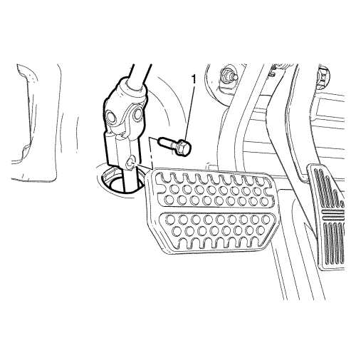
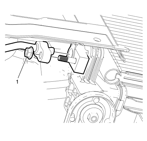
- Remove the lower intermediate steering shaft bolt (1).
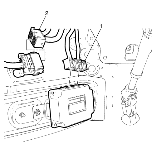
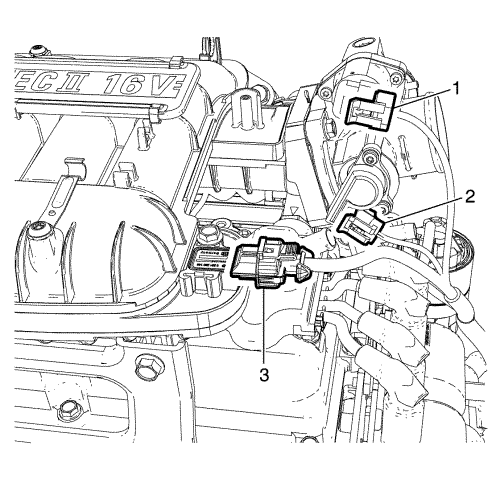
- Disconnect TCM connectors (1) and engine wiring harness (2).
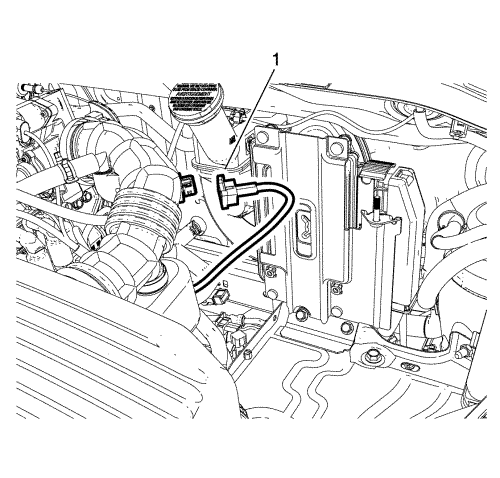
- Disconnect intake air temperature sensor connector (1).
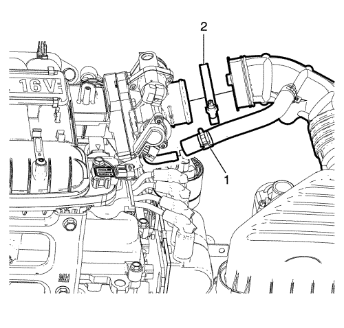
- Remove the clamps (1, 2).
- Twist and pull the hoses to remove throttle body assembly.
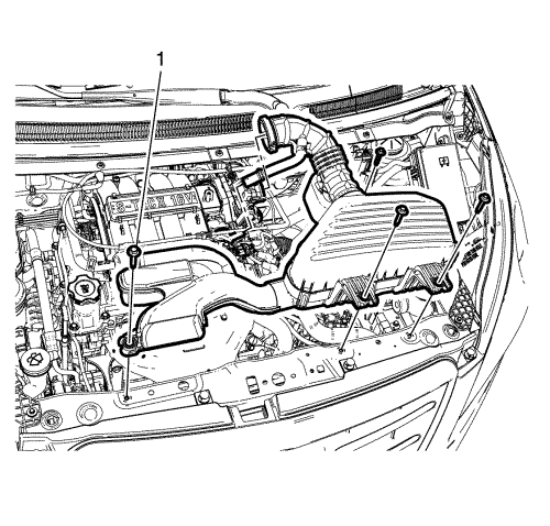
- Remove the 4 air cleaner assembly bolts (1).
- Remove the air cleaner assembly.
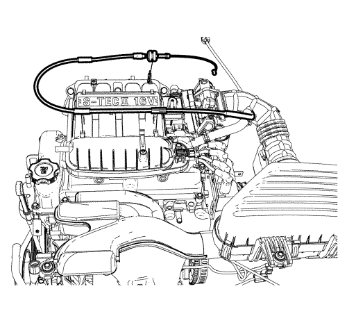
- Disconnect the accelerator cable, if equipped.
- Remove the battery. Refer to Battery Replacement .
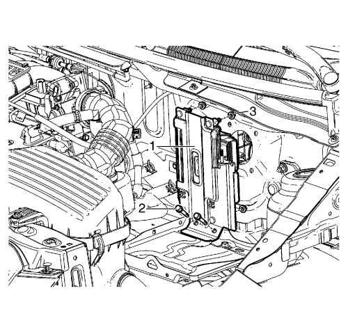
- Remove the engine control module (ECM) bracket to battery tray retaining bolts (2).
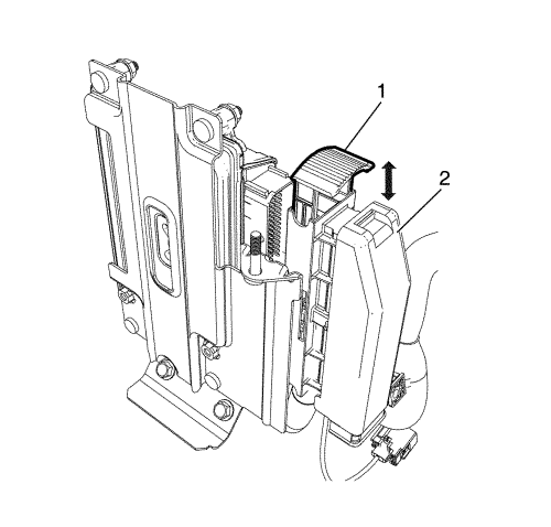
- Pull the engine control module (ECM) electrical connector lever (1). And disconnect the engine control module (ECM) electrical connector (2).
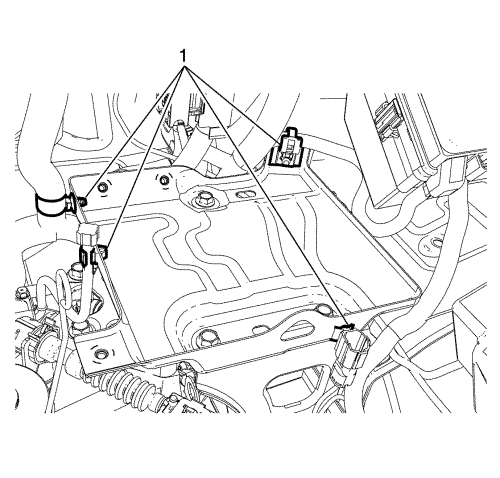
- Remove the retainers (1) from the battery tray with a suitable tool.
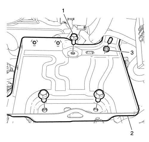
- Remove the bolts (1) and nut (3).
- Remove the battery tray (2).
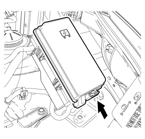
- Remove the under hood body electrical centre (BEC) cover.
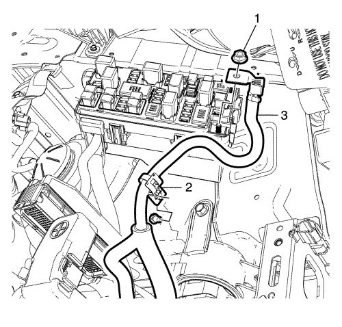
- Remove the positive cable to body electrical centre (BEC) retaining nut (1).
- Pull back the positive cable (3) to separate the positive cable retainer (2) from body.
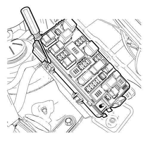
- Raise the upper plate with suitable tool.
- Remove the under hood BEC upper plate to lower plate retaining bolts (2).
- Disconnect the wiring harness plug (1) from the front compartment fuse block.
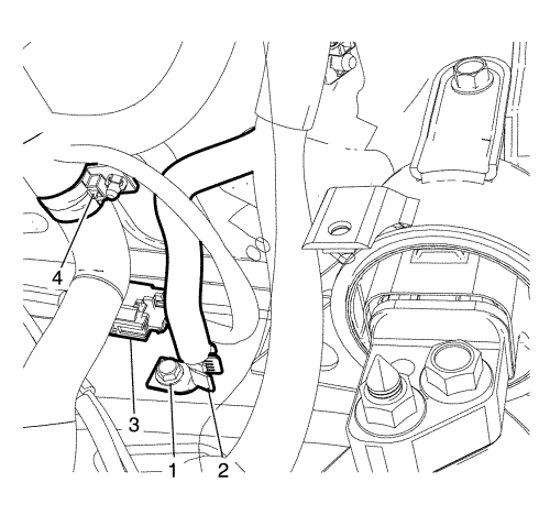
- Remove the ground bolt (1) and put the wiring harness (2) aside.
- Disconnect the wheel speed sensor connector (3).
- Move the wiring harness retainer (4) aside with suitable tool.
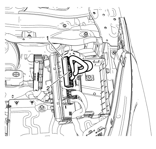
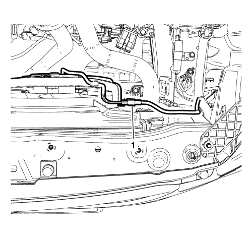
- Disconnect the heater inlet hose (1) and outlet hose (2) from the heater pipe.
Note: Plug or cap the hoses and inlets when separating the cooling system components, this prevents dirt and other contaminants from entering the cooling system.
- Plug or cap the cooling system hoses and inlets.
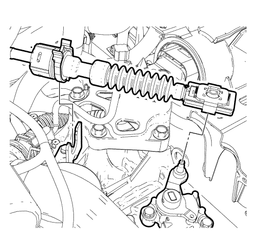
- Disconnect the transmission range selector lever cable terminal from the transmission lever pin. For manual gearbox refer to Manual Gearbox Gear Lever and Selector Lever Cable Replacement .
- Press the locking tabs inward in order to release the transmission range selector lever cable from the cable bracket.
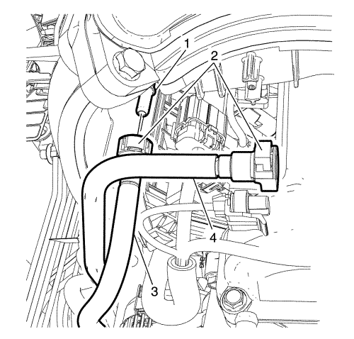
- Disconnect the pan module connector (1).
- Disconnect the ambient air temperature sensor connector (2) if equipped.
Note: Plug or cap the hoses and inlets when separating the cooling system components, this prevents dirt and other contaminants from entering the cooling system.
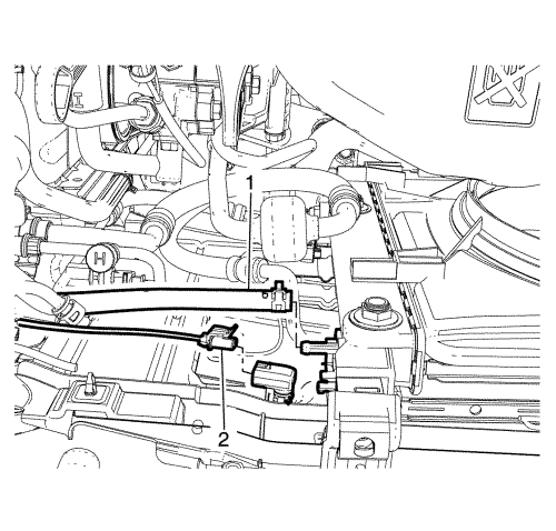
- Disconnect the coolant hose (1) from the CRFM.
Note: With the ignition OFF and the brakes cool, apply the brakes 3-5 times, or until the brake pedal becomes firm, in order to deplete the vacuum brake booster power reserve.
- Deplete the vacuum brake booster power reserve.
- Disconnect the vacuum hose (2) from upper intake manifold.
- Reposition and retain the vacuum hose (2) away from the powertrain.
- Raise the vehicle. Refer to Lifting and Jacking the Vehicle .
- Remove the front wheels. Refer to Tyre and Wheel Removal and Installation .
- Remove the front bumper fascia. Refer to Front Bumper Fascia Replacement .
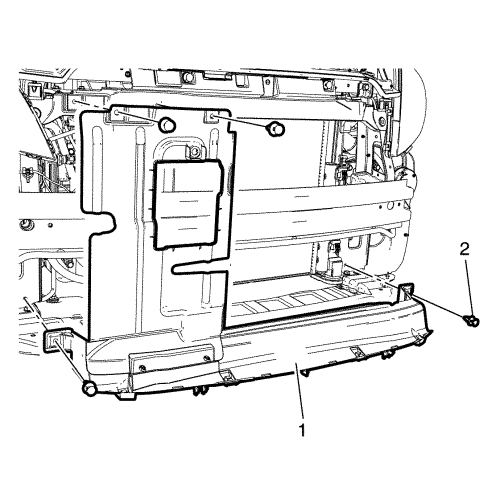
- Remove the clips (2).
- Remove the front air guard (1).
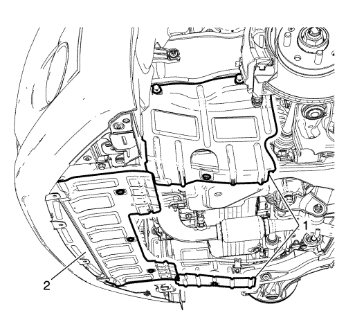
- Remove the cover (1, 2).
- Remove the clip (2) and the water deflector.
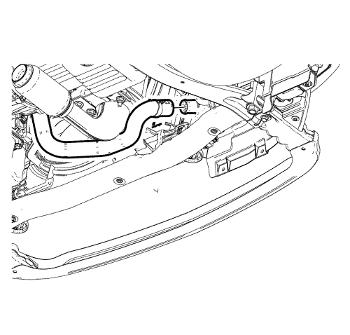
- Place a suitable container beneath the radiator and engine.
Note: Plug or cap the hoses and inlets when separating the cooling system components, this prevents dirt and other contaminants from entering the cooling system.
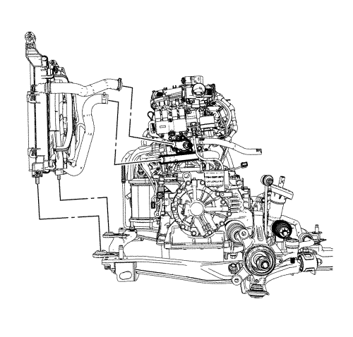
- Drain the cooling system by disconnecting lower coolant hose as shown.
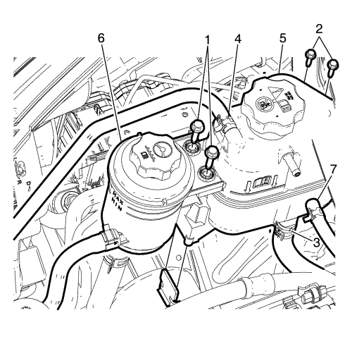
Note: DO not remove power steering fluid hose from power steering fluid reservoir.
- Remove power steering fluid reservoir bolts (1) And Unclip power steering fluid reservoir and retain it on the engine.
- Disconnect the coolant hoses (3, 4, 7) from the coolant surge tank.
Note: Plug or cap the hoses and inlets when separating the cooling system components, this prevents dirt and other contaminants from entering the cooling system.
- Plug or cap the cooling system hoses and inlets.
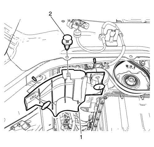
- Remove the coolant surge tank to body retaining bolts (2).
- Remove the coolant surge tank.
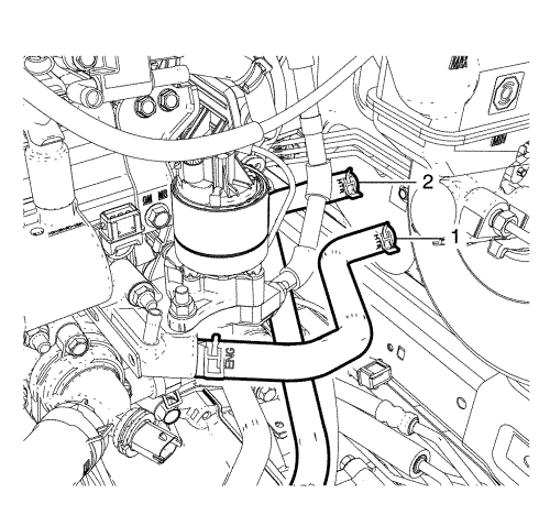
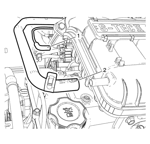
- Disconnect the fuel feed hose (3) from the fuel feed pipe (1).
Note: Plug or cap the fuel feed pipe (1) and fuel feed hose (3) ends to prevent fuel leaks and/or contamination.
- Plug or cap the fuel feed pipe (1) and fuel feed hose (3) ends.
- Disconnect the evaporative emission (EVAP) purge line (4) from the purge solenoid.
Note: When removal is complete plug hose openings with a clean lint free cloth to prevent foreign matter entry.
- Plug or cap the (EVAP) purge line (4) and the purge solenoid ends.
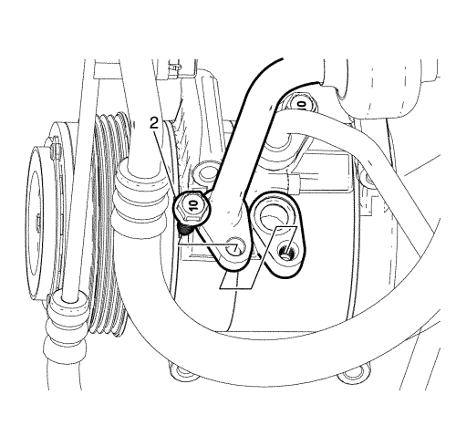
- Remove the suction/discharge line pad to A/C compressor retaining bolt (2).
- Disconnect the A/C suction/discharge line pad from the A/C compressor.
Note: Plug or cap the A/C suction/discharge pipe ends and the compressor ports immediately to prevent contamination and absorption of moisture from the atmosphere.
- Plug or cap the A/C suction/discharge pipe ends and the compressor ports.
Note: The A/C sealing O-rings are a single use component and will not reseal. Install NEW A/C sealing O-rings whenever the A/C suction/discharge line pad is removed from the A/C compressor.
- Remove and discard the A/C suction/discharge pipe sealing O-rings.
Note: Plug or cap the A/C suction/discharge pipe ends and the compressor ports immediately to prevent contamination and absorption of moisture from the atmosphere.
- Remove A/C compressor and condenser hose nut (1) from A/C condenser.
Note: DO NOT disconnect the hydraulic brake flexible hose from the brake calliper otherwise complete bleeding of the braking system will be necessary.
- Detach the front brake hose (2) from the strut mounted brake hose retaining bracket and remove the front brake calliper anchor plate to knuckle retaining bolts (1). Repeat for opposite side.
- Remove the front brake calliper from the front steering knuckle. Repeat for opposite side.
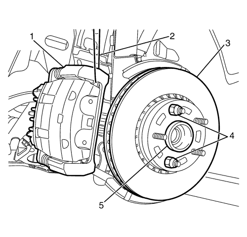
Caution: Support the brake calliper with heavy mechanic wire, or equivalent, whenever it is separated from its mount and the hydraulic flexible brake hose is still connected. Failure to support the calliper in this manner will cause the flexible brake hose to bear the weight of the calliper, which may cause damage to the brake hose and in turn may cause a brake fluid leak.
- Support the front brake calliper (1) with heavy mechanic's wire, or equivalent (2). Repeat for opposite side.
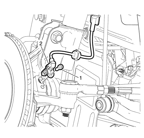
- Remove the wheel speed sensor retaining bolt (1) and detach wheel speed sensor harness (2) from the strut mounted retaining bracket.
- Secure away from the cradle and suspension components. Repeat for opposite side.
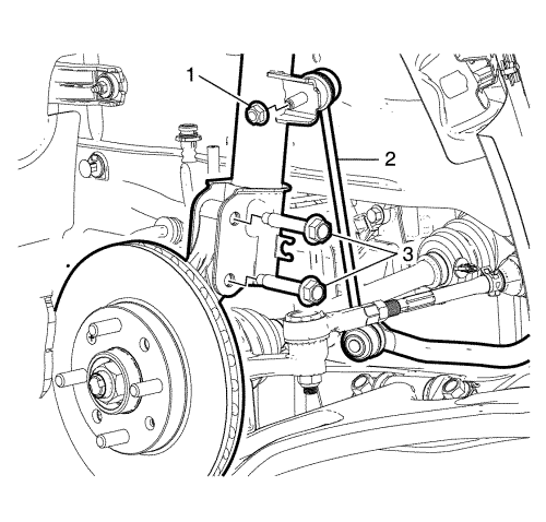
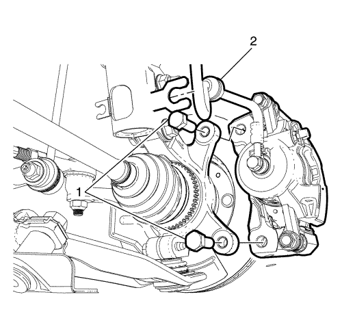
- Remove the bolts (3), opposite nuts, and nut (1).
- Remove the stabiliser shaft link (2) from the strut mounted retaining bracket. Repeat for opposite side.
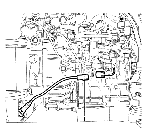
- Disconnect the oxygen sensor connector (1).
- Remove the exhaust flexible pipe. Refer to Exhaust Pipe Replacement .
Note: The SPX installation manual is supplied with the special tool and is also available online from SPX directly. Go to www.spxtools-shop.com.
- Assemble the CH-49290 engine support tool (1) according to the details provided in the SPX installation manual.
- Install the torque support (2) to the engine.
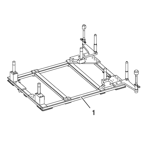
- Support the CH-904 base frame on a jack.
- Support the CH-49290 engine support tool on the CH-904 base frame.
Note: The SPX installation manual is supplied with the special tool and is also available online from SPX directly.
- Install the CH-49290 engine support tool (1) according to the details provided in the SPX installation manual.
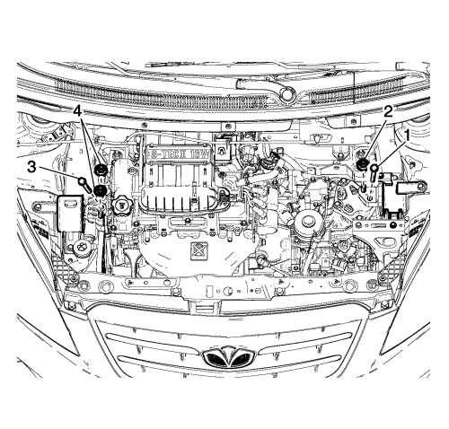
- Remove the engine mount retaining bolt (3) and nuts (4).
- Remove the transmission retaining bolt (1) and nut (2).
Note: The SPX installation manual is supplied with the special tool and is also available online from SPX directly. Go to www.spxtools-shop.com.
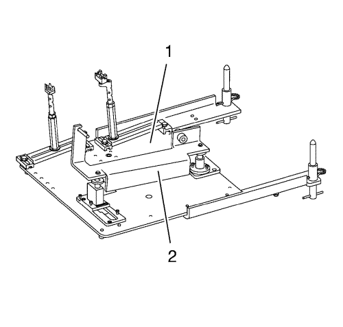
- Assemble the CH-49289 centring frame (1) according to the details provided in the SPX installation manual.
- Support the CH-904 base frame on a jack.
- Support the CH-49289 centring frame on the CH-904 base frame.
Note: The SPX installation manual is supplied with the special tool and is also available online from SPX directly.
- Install the CH-49289 centring frame (1) according to the details provided in the SPX installation manual.
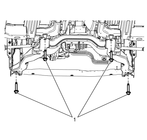
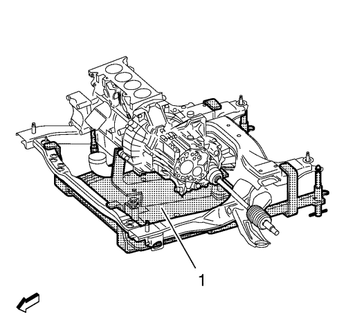
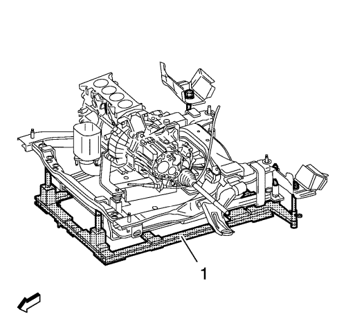
- Remove the frame to body bolts (1).
- Slowly lower the jack stand and remove the frame with the engine from the vehicle.
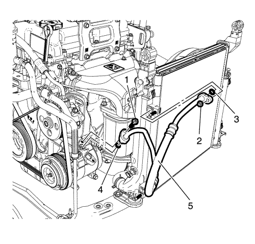
- Remove the suction/charge line pad to A/C compressor retaining bolt (1) and suction/charge line pad to condenser retaining nut (2).
- Disconnect the A/C suction/charge line pad (5) from the A/C compressor.
Note: Plug or cap the A/C suction/discharge pipe ends and the compressor ports immediately to prevent contamination and absorption of moisture from the atmosphere.
- Plug or cap the A/C suction/charge pipe ends, condenser ports and the compressor ports.
Note: The A/C sealing O-rings are a single use component and will not reseal. Install NEW A/C sealing O-rings whenever the A/C suction/discharge line pad is removed from the A/C compressor.
- Remove and discard the A/C suction/charge pipe sealing O-rings (3, 4).
- Discard the O-rings.
- Remove the condenser radiator fan module (CRFM).
- Disconnect the idle air control valve (IACV) connector (1), throttle position sensor (TPS) connector (2), manifold absolute pressure (MAP) sensor connector (3).
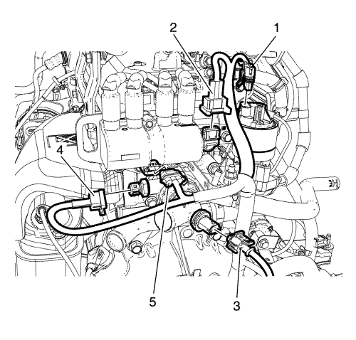
- Disconnect the EGR connector (1), camshaft position sensor connector (2), thermostat heater connector (3), engine coolant temperature sensor connector (4) and DIS connector (5).
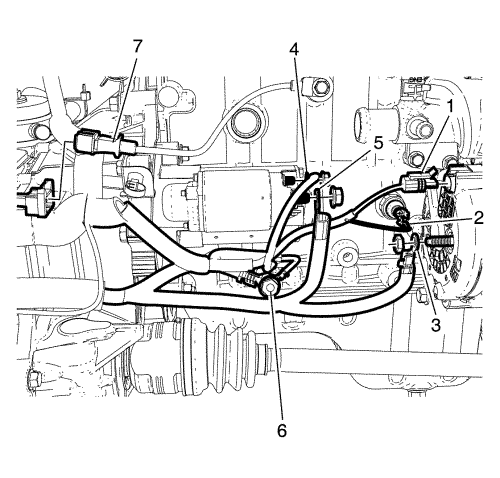
- Disconnect the alternator harness connector (1), oil pressure switch connector (2) and knock sensor connector (7).
- Remove the battery positive cable to alternator retaining nut.
- Disconnect the battery positive cable (3) from the alternator.
- Remove the battery cable harness to starter motor retaining nut.
- Disconnect the battery cable harness (4, 5) from the starter motor.
- Remove the engine wiring harness ground to cylinder block retaining bolt (6).
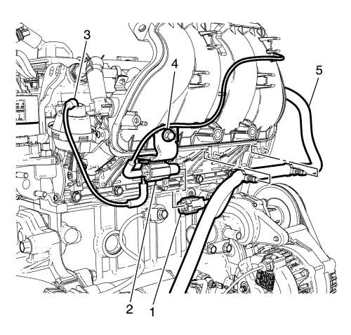
- Disconnect the intake manifold runner control valve connector (1) and detach the wiring harness (5) from intake manifold.
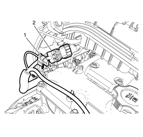
- Disconnect the canister purge solenoid connector (1) and the injector harness electrical connector (2).
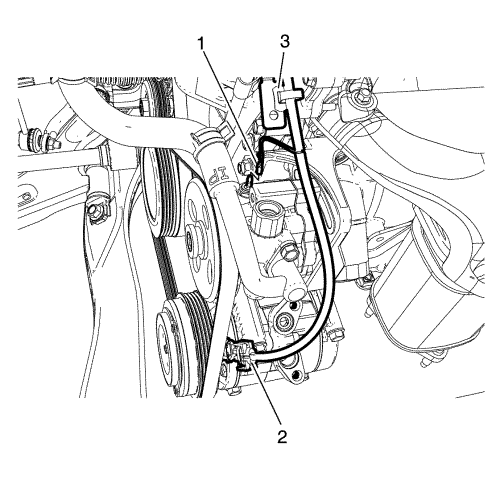
- Disconnect the power steering connector (1), and A/C compressor electrical connector (2).
- Detach the engine wiring harness clip (3) from the bracket.
- Remove the engine wiring harness from the powertrain.
- Remove the power steering belt. Refer to Power Steering Pump Belt Removal .
- Remove the drive belt. Refer to Drive Belt Removal .
- Remove the power steering pump. Refer to Power Steering Pump Replacement .
- Remove the A/C compressor. Refer to Air Conditioning Compressor Replacement .
- Remove the generator. Refer to Generator Replacement .
- Loosen the transmission bolts and remove. Refer to Transmission Replacement for the Y4M transmission and Transmission Replacement for the Jatco transmission.
- Attach a suitable lifting chain and hooks to lift bracket.
- Using a suitable lifting crane, raise the engine.
- Install the engine to a suitable engine stand.
- Transfer parts as needed.


