To the top of the document
Captiva
   
GMDE Start Page Load static TOC Load dynamic TOC Help?

Tyre-to-Wheel Match-Mounting (Vectoring)


182218

Note: After remounting a tyre to a wheel or after replacing a tyre and/or a wheel, remeasure the tyre and wheel assembly runout in order to verify that the amount of runout has been reduced and brought to within tolerances. Ensure that the tyre and wheel assembly is properly balanced before reinstalling to the vehicle.
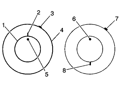
  1. Mark the location of the high spot (3) on the tyre as determined during the off-vehicle tyre and wheel assembly runout measurement.
  2. Place a reference mark (2) on the tyre sidewall at the location of the valve stem (5).
  3. • Always refer to the valve stem as the 12 o'clock position.
    • Refer to the location of the high spot (3) by its clock position on the wheel, relative to the valve stem.
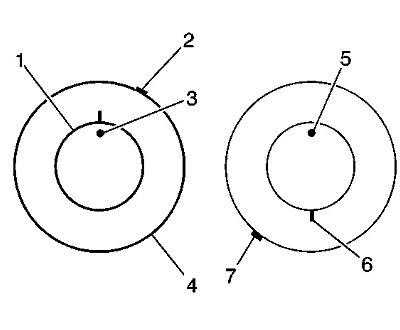
  4. Mount the tyre and wheel assembly on a tyre machine and break down the bead. Do not dismount the tyre from the wheel at this time.
  5. Rotate the tyre 180 degrees on the rim so that the valve stem reference mark (8) is now at the 6 o'clock position in relation to the valve stem (6). You may need to lubricate the bead in order to easily rotate the tyre on the wheel.
  6. Re-inflate the tyre and seat the bead properly.
  7. Mount the assembly on the tyre balancer and remeasure the runout. Mark the new location of the assembly runout high spot on the tyre.
  8. If the assembly runout has been reduced and is within tolerance, no further steps are necessary. Balance the tyre and wheel assembly, then install the assembly to the vehicle. Refer to the following:
  9. •  Tyre and Wheel Assembly Balancing - Off Vehicle
    •  Tyre and Wheel Removal and Installation
  10. If the clock location of the high spot remained at or near the original clock location of the high spot (7) and the assembly runout has NOT been reduced, the wheel is the major contributor to the assembly runout concern.

  11. 182231
  12. If the clock location of the high spot has moved, however the assembly runout has NOT been reduced, perform the following steps:
  13. 9.1. If the clock location of the high spot (7) is now at or near a position 180 degrees from the original clock location of the high spot, the tyre is the major contributor to the assembly runout concern.
    9.2. If the clock location of the high spot is now in-between the 2 extremes, then both the tyre and the wheel are both contributing to the assembly runout concern. Rotate the tyre an additional 90 degrees in both the clockwise and the anticlockwise directions to obtain the lowest amount of assembly runout.


© Copyright Chevrolet. All rights reserved