Camshaft Timing Chain, Sprocket, and Tensioner Replacement - LE5 or LE9
Special Tools
| • | EN-45027 Tensioner Tool |
| • | EN-48953 Camshaft Actuator Locking Tool |
For equivalent regional tools, refer to
Special Tools : LE5 or LE9
Removal Procedure
- Remove the number 1 cylinder spark plug. Refer to Spark Plug Replacement .
- Rotate the crankshaft in the engine rotational direction clockwise, until the number 1 piston is at top dead centre (TDC) on the exhaust stroke.
- Remove the camshaft cover. Refer to
Camshaft Cover Replacement : LE5 or LE9 .
- Remove the engine front cover. Refer to
Engine Front Cover Replacement : LE5, LE9 or LAF .
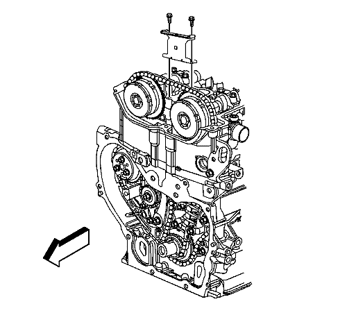
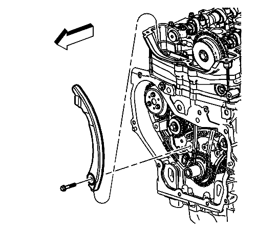
- Remove the upper timing chain guide bolts and guide.
Note: The timing chain tensioner must be removed to unload chain tension before the timing chain is removed. If it is not, the timing chain will become cocked and it will be difficult to remove.
- Remove the timing chain tensioner.
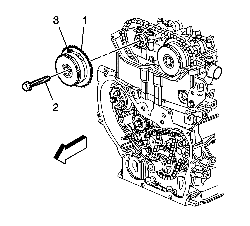
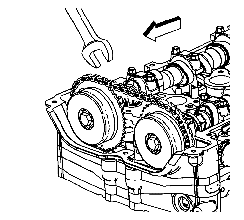
- Install a 24 mm wrench on the hex on the exhaust camshaft in order to hold the camshaft.
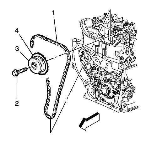
- Remove and discard the exhaust camshaft actuator bolt (2).
- Remove the exhaust camshaft actuator (1, 3) from the camshaft and timing chain.
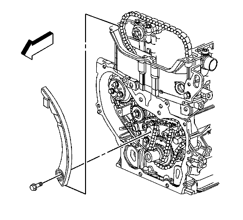
- Remove the timing chain tensioner guide bolt and guide.
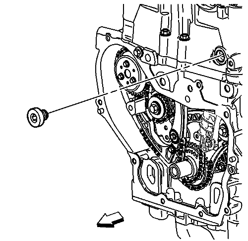
- Remove the fixed timing chain guide access plug.
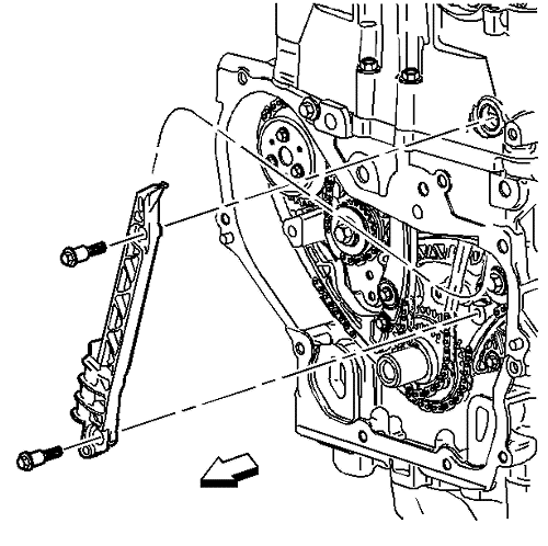
- Remove the fixed timing chain guide bolts and guide.
- Install a 24 mm wrench on the hex on the intake camshaft in order to hold the camshaft.
- Remove and discard the intake camshaft actuator bolt (2).
- Remove the intake camshaft actuator (3), and the timing chain through the top of the cylinder head.
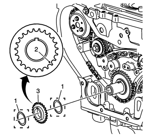
Note: Ecotec 4 cylinder engines with SIDI-Direct Injection, the lower timing chain crank gear may be equipped with a second spacing washer installed in front of the lower timing chain crank gear. The outer spacer/washer is in between the crank/balancer pulley and the lower timing gear and may remain in place when the pulley is removed. The spacer/washer has a dot/mark on its surface that may be mistaken for the lower timing mark. If applicable, the washer must be removed in order to view the correct timing mark on the lower crank gear.
- Remove the outer friction washer (1) if equipped.
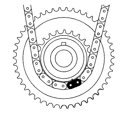
- Ensure the crankshaft gear timing mark (2) is in the 5 o'clock position and crankshaft key is in the 12 o'clock position.
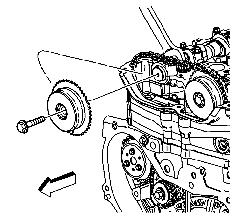
- Remove the crankshaft sprocket (3).
- Remove the inner friction washer (1).
Installation Procedure
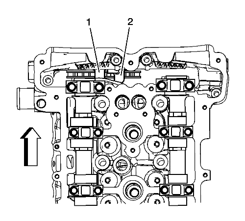
- On 2.2L engines, ensure the intake camshaft notch is in the 10 o'clock position (2) and the exhaust camshaft notch is in the 7 o'clock position (1). The number 1 piston should be at TDC, crankshaft key at 12 o'clock.

- On 2.4L engines, ensure the intake camshaft notch is in the 5 o'clock position (2) and the exhaust camshaft notch is in the 7 o'clock position (1). The number 1 piston should be at TDC, crankshaft key at 12 o'clock.
Note: Ecotec 4 cylinder engines with SIDI-Direct Injection, the lower timing chain crank gear may be equipped with a second spacing washer installed in front of the lower timing chain crank gear. The outer spacer/washer is in between the crank/balancer pulley and the lower timing gear and may remain in place when the pulley is removed. The spacer/washer has a dot/mark on its surface that may be mistaken for the lower timing mark. If applicable, the washer must be removed in order to view the correct timing mark on the lower crank gear.
- Install the inner friction washer (1).
- Install the crankshaft sprocket with the timing mark (2) is in the 5 o'clock position and facing outward.
- Install the outer friction washer (1) if equipped.
Note:
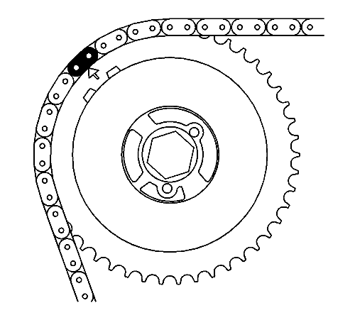
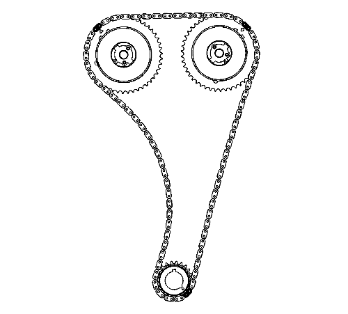
| • | There are 3 coloured links on the timing chain. Two links are of matching colour, and 1 link is of a unique colour. Use the following procedure to line up the links with the actuators. Orient the chain so that the colored links are visible. |
| • | Always use new actuator bolts. |
- Assemble the intake camshaft actuator into the timing chain with the timing mark lined up with the uniquely colored link (1).
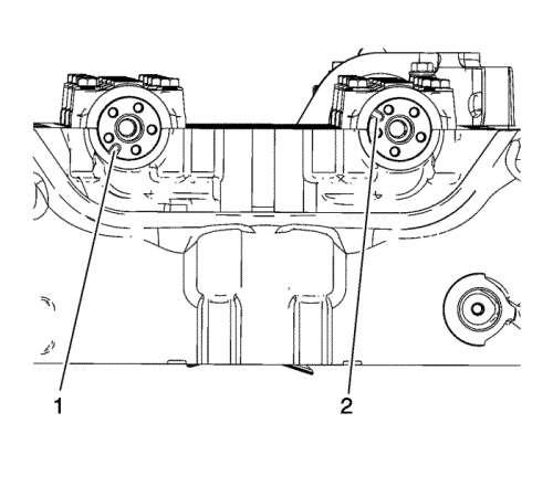
- Lower the timing chain through the opening in the cylinder head. Use care to ensure that the chain goes around both sides of the cylinder block bosses (1, 2).
- Install the intake camshaft actuator onto the intake camshaft while aligning the dowel pin into the camshaft slot.
- Hand tighten the new intake camshaft actuator bolt.
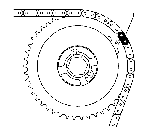
- Route the timing chain around the crankshaft sprocket and line up the first matching coloured link with the timing mark on the crankshaft sprocket, approximately in the 5 o'clock position.
- Install the friction washer, if applicable.
- Rotate the crankshaft clockwise to remove all chain slack. Do not rotate the intake camshaft.
Caution: Refer to Fastener Caution in the Preface section.
- Install the adjustable timing chain guide down through the opening in the cylinder head and install the adjustable timing chain bolt. Tighten the adjustable timing chain guide bolt to 10 N·m (89 lb in).
Note: Always install NEW actuator bolts.
- Install the exhaust camshaft actuator into the timing chain with the timing mark lined up with the second matching coloured link.
- Install the exhaust camshaft actuator onto the exhaust camshaft, aligning the dowel pin into the camshaft slot.
- Use a 24 mm open-ended wrench, rotate the exhaust camshaft approximately 45 degrees until the dowel pin in the camshaft actuator goes into the camshaft slot.
- When the actuator seats on the cam, tighten the new exhaust camshaft actuator bolt hand tight.
- Verify that all of the colored links and the appropriate timing marks are still aligned. If they are not aligned, repeat the portion of the procedure necessary to align the timing marks.
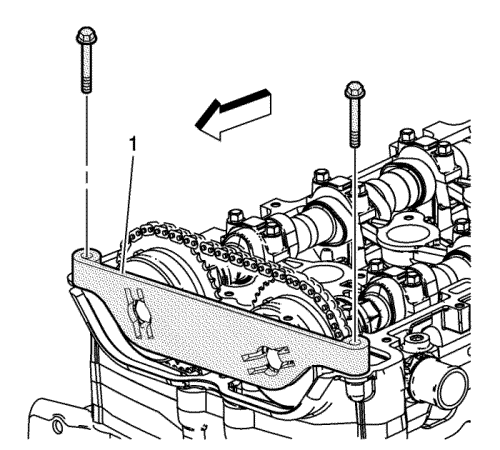
- Install the fixed timing chain guide and bolts. Tighten the fixed timing chain guide bolts to 10 N·m (89 lb in).
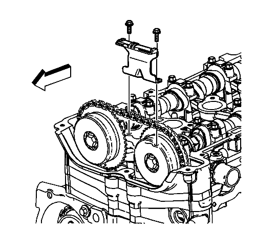
- Install the upper timing chain guide and bolts. Tighten the upper timing chain guide bolts to 10 N·m (89 lb in).
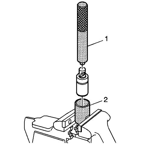
- Reset the timing chain tensioner by performing the following steps:
| 21.1. | Remove the snap ring. |
| 21.2. | Remove the piston assembly from the body of the timing chain tensioner. |
| 21.3. | Install the EN-45027-2 tool (2) in a vice. |
| 21.4. | Install the notch end of the piston assembly into the EN-45027-2 tool (2). |
| 21.5. | Using the EN-45027-1 tool (1), turn the ratchet cylinder into the piston. |
| 21.6. | Reinstall the piston assembly into the body of the tensioner. |
| 21.7. | Install the snap ring. |
- Inspect the timing chain tensioner seal for damage. If damaged, replace the seal.
- Inspect to ensure all dirt and debris is removed from the timing chain tensioner threaded hole in the cylinder head.
Note: Ensure the timing chain tensioner seal is centered throughout the torque procedure to eliminate the possibility of an oil leak.
- Install the timing chain tensioner assembly. Tighten the timing chain tensioner to 75 N·m (55 lb ft).
- The timing chain tensioner is released by compressing it 2 mm (0.079 in), which will release the locking mechanism in the ratchet. To release the timing chain tensioner, use a suitable tool with a rubber tip on the end. Feed the tool down through the cam drive chest to rest on the cam chain. Then give a sharp jolt diagonally downwards to release the tensioner.
- Install EN-48953 locking tool (1) and tighten the bolts into the cylinder head to 10 N·m (89 lb in).
- Using a torque wrench, tighten the camshaft actuator bolt to 30 N·m (22 lb ft) plus 100 degrees using the EN-45059 meter.
- Remove the EN-48953 locking tool .
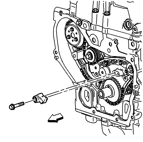
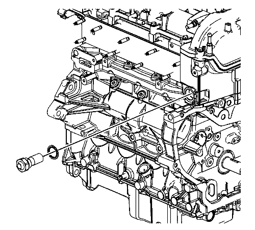
- Install the timing chain oiling nozzle. Tighten the timing chain oiling nozzle bolt to 10 N·m (89 lb in).
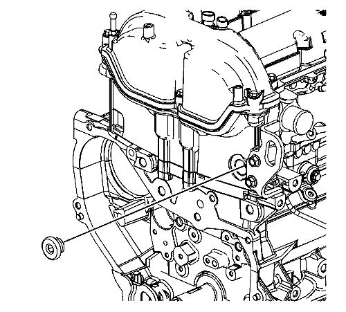
- Apply sealant compound to the thread of the timing chain guide bolt access hole plug. Refer to Adhesives, Fluids, Lubricants, and Sealers
- Install the timing chain guide bolt access hole plug. Tighten the access hole plug to 90 N·m (66 lb ft).
- Install the engine front cover. Refer to
Engine Front Cover Replacement : LE5, LE9 or LAF .
- Install the camshaft cover. Refer to
Camshaft Cover Replacement : LE5 or LE9 .
- Install the number 1 cylinder spark plug. Refer to Spark Plug Replacement .
| © Copyright Chevrolet. All rights reserved |


