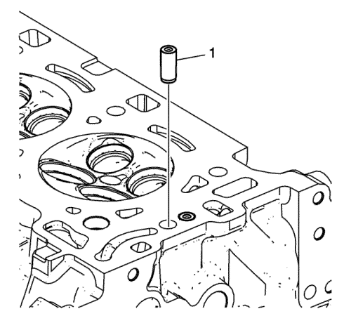
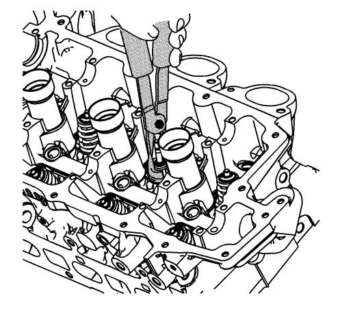
- Use lubricant included with EN 46122 remover/installer to lubricate outside of the new check valve (1).
- With the check ball end of the check valve facing UP, away from the head, insert the NEW check valve into the check valve bore in the cylinder head.
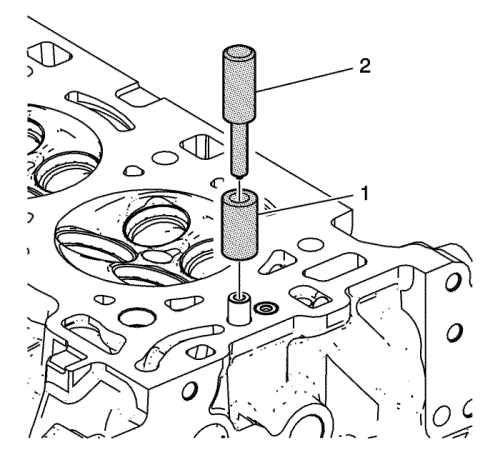
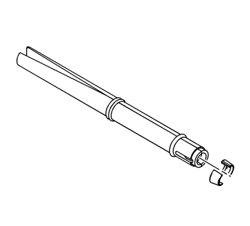
- Place collar EN 46122-2 (1) over the new check valve with the slightly larger inside diameter of the collar DOWN toward the cylinder head.
- Using the driver EN 46122-1 (2), lightly tap the new check valve into place until the driver stops against the top of the collar.
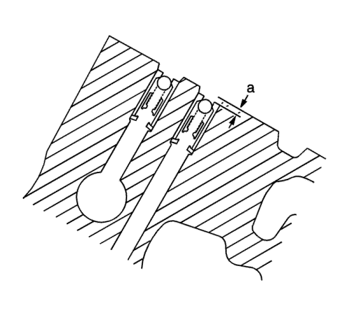
- Inspect the camshaft position actuator oil feed check valves in order to ensure they are properly installed in the cylinder head. The camshaft position actuator oil feed check valve should be flush to 2 mm (0.0787 in) below the cylinder head deck surface (a).
Caution: Refer to Fastener Caution in the Preface section.
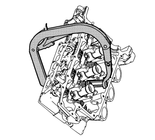
- Install the cylinder head coolant threaded plugs and tighten to 31 N·m (23 lb ft).
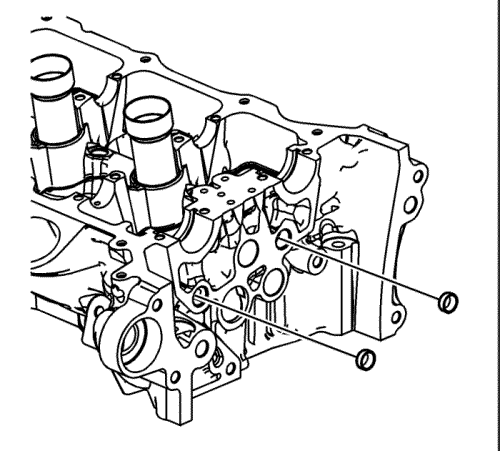
- Install the NEW cylinder head oil gallery expansion plugs.
- Place the valve stem oil seals onto the guides.
Note: NEVER reuse a valve stem oil seal. Always use new seals when assembling the cylinder head.
- Mount a new valve stem oil seal using the EN 46116 remover/installer .
Note: Force should only be applied to the valve spring contact area of the new valve stem oil seal during installation.
- Push and twist the valve stem oil seal into position on the valve guide until the seal positively locks on the guide using the EN 46116 remover/installer .
- Lubricate the valve stem and valve guide ID with clean engine oil. Refer to Adhesives, Fluids, Lubricants, and Sealers for recommended lubricant.
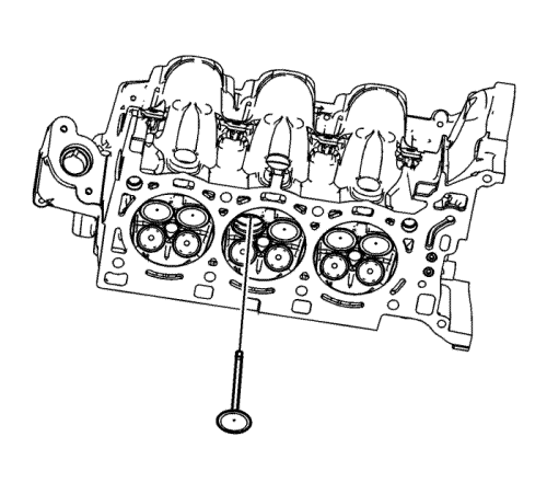
Note: The valve stem oil seal must not come loose from the valve guide when the valve is installed.
- Insert the valve into the valve guide until it bottoms on the valve seat.
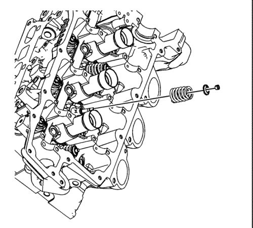
- Position the valve spring on the spring seat.
- Place the valve spring retainer onto the valve spring.
Warning: Compressed valve springs have high tension against the valve spring compressor. Valve springs that are not properly compressed by or released from the valve spring compressor can be ejected from the valve spring compressor with intense force. Use care when compressing or releasing the valve spring with the valve spring compressor and when removing or installing the valve stem keys. Failing to use care may cause personal injury.
Caution: Do not compress the valve springs to less than 24.0 mm (0.943 in). Contact between the valve spring retainer and the valve stem oil seal can cause potential valve stem oil seal damage.
- Compress the valve spring using the EN 8062 compressor and the EN 46119 adapter.
Note: Ensure proper directional placement of valve keepers in the EN 46117 remover/installer . The valve keepers must be installed with the tapered end towards the valve stem seal.
- With the spring compressed, install the valve keepers into the EN 46117 remover/installer .
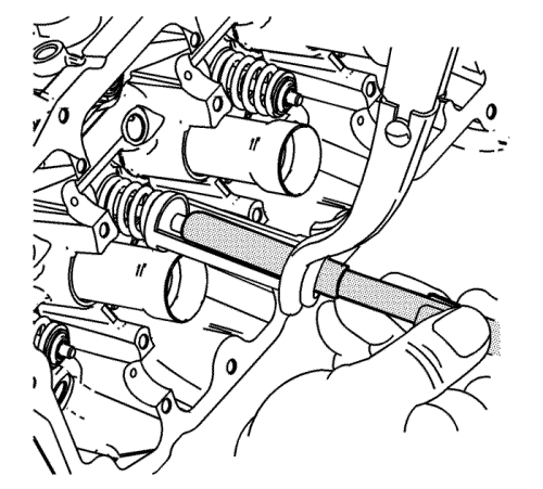
- Place the keepers into position by pushing the tool downward. While holding the tool lightly together in the area between the O-rings, using the thumb and forefinger, release tension on the EN-46119 adapter and the EN 8062 compressor . This will slowly push the EN-46117 remover/installer off the valve stem, leaving the keepers in place.
- Verify that the valve keepers are installed by placing a rag over the valve tip and tapping with a dead-blow hammer.
Note: If the fuel rail was removed from the cylinder head, the fuel injector tip seals must be replaced. Refer to Fuel Rail and Injectors Cleaning and Inspection : LF1, LFW or LFX .
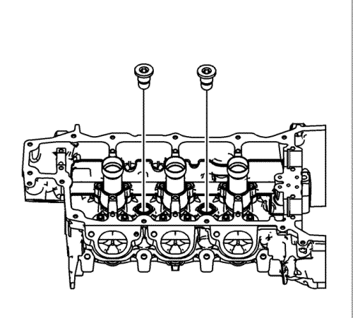
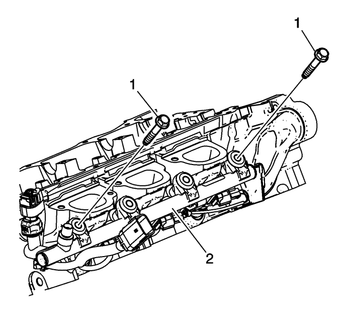
- Install the fuel rail with injectors (2) into the cylinder head evenly.
- Install and hand-tighten the two outer fuel rail bolts (1) to seat the injectors in the injector bores.
- Install and hand-tighten the two inner fuel rail bolts.
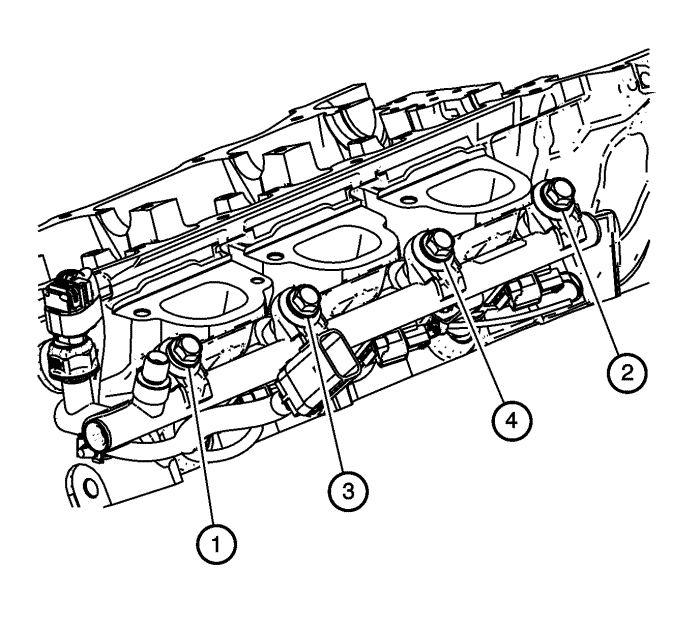
- Tighten the fuel rail bolts in the sequence shown to 25 N·m (18 lb ft).


