Piston, Connecting Rod, and Bearing Replacement
Special Tools
EN-45059 Angle Meter
For equivalent regional tools, Refer to Special Tools .
Removal Procedure
- Open the hood.
- Remove the cylinder head. Refer to Cylinder Head Replacement .
- Remove the oil pan. Refer to Oil Pan Replacement .
- Raise and support the vehicle. Refer to Lifting and Jacking the Vehicle .
- Install the crankshaft pulley bolt.
- Set the pistons 1 and 4 to TDC in direction of engine rotation.
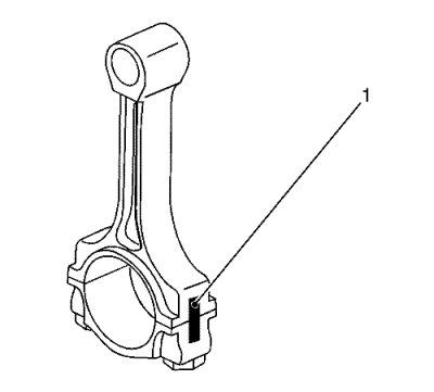
Note: Observe the cylinder sequence.
- Mark the connecting rod with the connecting rod bearing cover (1).
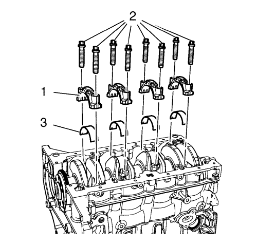
- Remove and DISCARD the 4 connecting rod bearing caps bolts (2) of cylinder 1 and 4.
- Remove the connecting rod bearing caps (1) and the connecting rod bearing (3).
- Lower the vehicle.
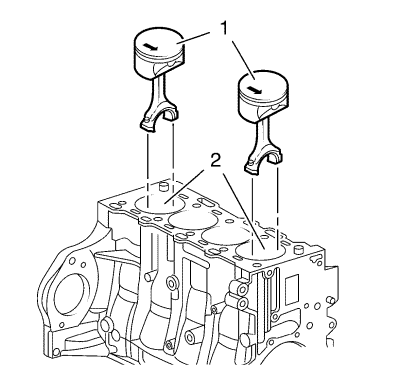
- Push the pistons 1 and 4 (1) out of the cylinder bore (2).
Note: The shear surfaces of the con-rod and the con-rod bearing cover form a unique fit and must not be swapped or damaged. Do not lay down on the shear surfaces.
- Remove the pistons 1 and 4 (1).
- Turn crankshaft on crankshaft balancer through 180° in direction of rotation of engine.

Note: Observe cylinder sequence.
- Mark the connecting rod with the connecting rod bearing cover (1).
- Raise the vehicle.

- Remove and DISCARD the 4 connecting rod bearing caps bolts (2) of cylinder 2 and 3.
- Remove the connecting rod bearing caps (1) and the connecting rod bearing (3).
- Lower the vehicle.
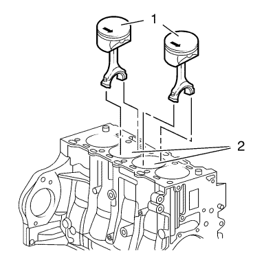
- Push the pistons 2 and 3 (1) out of the cylinder bore (2).
Note: The shear surfaces of the con-rod and the con-rod bearing cover form a unique fit and must not be swapped or damaged. Do not lay down on the shear surfaces.
- Remove the pistons 2 and 3 (1).
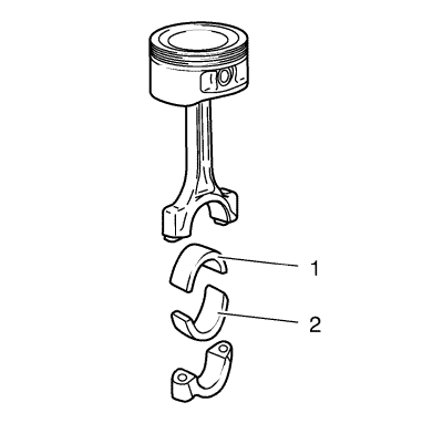
Note: Observe correct fitting position, observe alignment.
- Remove the connecting rod bearing (1, 2).
- Check the components. Refer to Piston, Connecting Rod, and Bearing Cleaning and Inspection .
Installation Procedure

Note: Lubricate the connection rod bearing with NEW engine oil.
- Install the connecting rod bearing (1, 2).
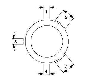
- Set piston ring joints.
| • | Piston compression upper ring in position (1). |
| • | Piston compression lower ring in position (4). |
| • | Interim ring of the piston oil ring rail in position (5), steel band rings of the piston oil ring rail in position (2) and/or (3). |
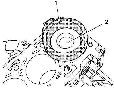
- Lubricate the piston rings, piston (1), inner cylinder bore surface and EN-48249 compressor (2) with clean engine oil.

Note: Arrow on piston head points to engine timing side, bead on connecting rod points to transmission side of engine.
- Push the pistons 2 and 3 (1) into the cylinder bore (2).
- Raise the vehicle.

- Install the connecting rod bearing caps (1) and the connecting rod bearing (3).
- Install 4 NEW connecting rod bearing caps bolts (2) of cylinder 2 and 3 and tighten in 3 passes:
Caution: Refer to Fastener Caution in the Preface section.
Caution: Refer to Torque-to-Yield Fastener Caution in the Preface section.
| 7.1. | In first pass tighten to 25 N·m (18 lb ft). |
| 7.2. | In second pass tighten to 30 ° using the EN-45059 meter . |
- Turn crankshaft on crankshaft balancer through 180° in direction of rotation of engine.
- Lower the vehicle.

- Push the pistons 1 and 4 (1) into the cylinder bore (2).
- Raise the vehicle.

- Install the connecting rod bearing caps (1) and the connecting rod bearing (3).
- Install the 4 NEW connecting rod bearing caps bolts (2) of cylinder 1 and 4 and tighten in 3 passes:
| 13.1. | In first pass tighten to 25 N·m (18 lb ft). |
| 13.2. | In second pass tighten to 30 ° using the EN-45059 meter . |
- Set the crankshaft in direction of engine rotation to 60 ° before TDC.
- Install the crankshaft pulley bolt.
- Install the oil pan. Refer to Oil Pan Replacement .
- Install the cylinder head. Refer to Cylinder Head Replacement .
- Close the hood.
| © Copyright Chevrolet. All rights reserved |


