Electronic Brake Control Module Replacement
Removal Procedure
Warning: Refer to Brake Fluid Irritant Warning in the Preface section.
Caution: Refer to Brake Fluid Effects on Paint and Electrical Components Caution in the Preface section.
Caution: Always connect or disconnect the wiring harness connector from the EBCM/EBTCM with the ignition switch in the OFF position. Failure to observe this precaution could result in damage to the EBCM/EBTCM.
Note: The transmission must be in the PARK position, the power button in the OFF position, and the brakes not applied to ensure the brake modulator and high pressure accumulator (HPA) pressure relief occurs. This process will take approximately 1 to 3 minutes.
- Place the transmission in PARK.
- Place the power button in the OFF position.
- Remove the remote keyless entry (RKE) transmitter and close all of the vehicle doors.
- Wait approximately 3 minutes for the HPA pressure relief to occur.
- Remove the front suspension strut housing brace. Refer to Front Suspension Strut Housing Brace Replacement .
- Disconnect the electronic brake control module (EBCM) electrical connector.
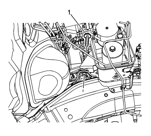
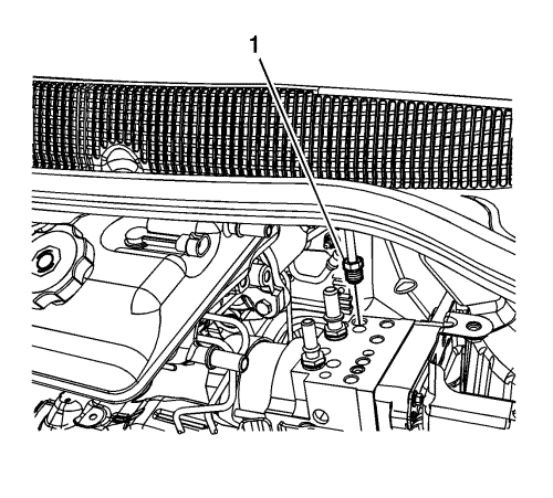
- Remove the brake pressure modulator valve (BPMV) bracket bolt (1).
- Without disconnecting the connectors, remove the fasteners and position the drive motor generator power inverter module aside. Refer to Drive Motor Generator Power Inverter Module Replacement .
- Remove the bolt and position aside the engine wiring junction block.

- Disconnect the BPMV return hose quick connect (1).
- Cap the BPMV outlet port and plug the return hose to prevent brake fluid loss and contamination.
- Disconnect the BPMV supply hose quick connect (1).
- Cap the BPMV inlet port and plug the supply hose to prevent brake fluid loss and contamination.
Note: Mark the location of the brake pipe fittings at the BPMV to ensure correct installation.
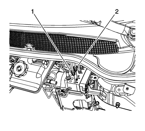
- Disconnect the right rear (1) and left rear (2) brake pipe fittings from the BPMV.
- Cap the brake pipe fittings and the BPMV outlet ports to prevent brake fluid loss and contamination.
Note: Mark the location of the brake pipe fittings at the BPMV to ensure correct installation.
- Disconnect the left front (1) and right front (2) secondary brake pipe fittings from the BPMV.
- Cap the brake pipe fittings and the BPMV outlet ports to prevent brake fluid loss and contamination.
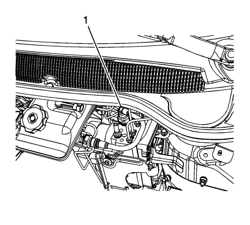
- Disconnect the master cylinder primary brake pipe fitting (1).
- Cap the brake pipe fitting and the BPMV inlet port to prevent brake fluid loss and contamination.
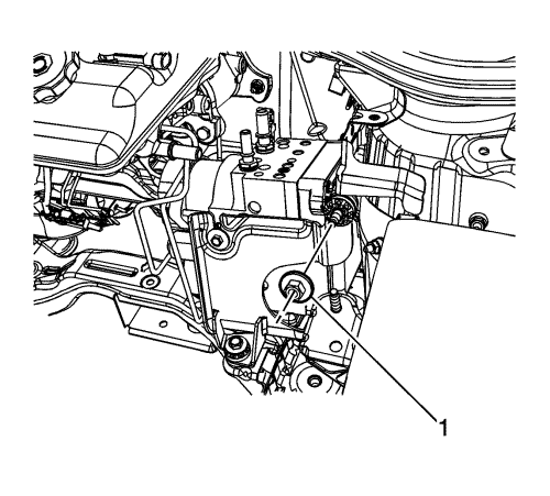
- Remove the BPMV bracket nut (1).
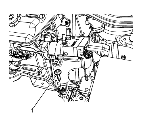
- Remove the BPMV bracket bolt (1).
- Remove the brake master cylinder. Refer to Master Cylinder Replacement .
- Carefully move the front brake pipes and remove the hydraulic control unit and bracket assembly.
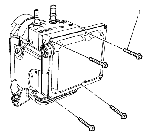
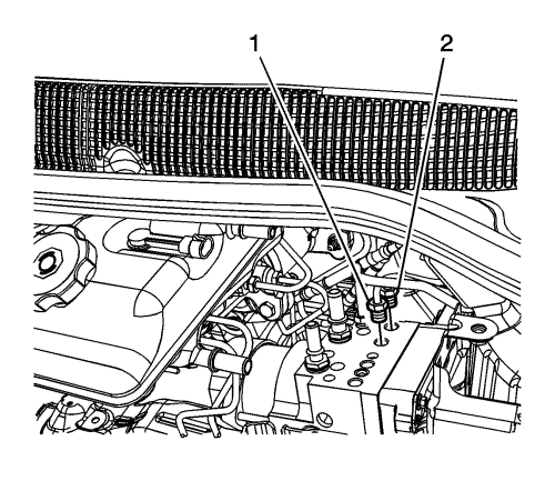
- Remove the EBCM bolts (1).
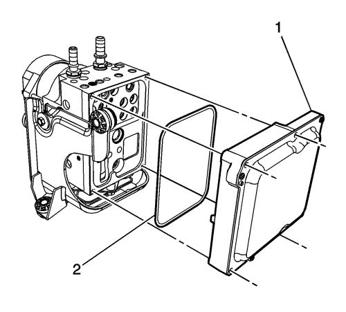
Note: Do not pry the EBCM from the BPMV. The EBCM must be pulled back evenly.
- Carefully separate the EBCM (1) and seal (2) from the BPMV. Do not pry or force the components apart.
Installation Procedure
- Clean the sealing surfaces of the EBCM and the BPMV with denatured alcohol or equivalent and allow to dry.
- Install the EBCM (1) and seal (2) to the BPMV.
Caution: Refer to Fastener Caution in the Preface section.
- Install the EBCM bolts (1) and tighten to 3 N·m (27 lb in).
- Carefully move the front brake pipes and install the hydraulic control unit and bracket assembly.
- Install the BPMV bracket bolt (1) and tighten to 22 N·m (16 lb ft).
- Install the BPMV bracket nut (1) and tighten to 22 N·m (16 lb ft).
- Install the brake master cylinder. Refer to Master Cylinder Replacement .
- Install the master cylinder primary brake pipe and tighten the fitting (1) to 23 N·m (17 lb ft).
- Install the left front (1) and right front (2) secondary brake pipes and tighten the fittings to 19 N·m (14 lb ft).
- Install the right rear (1) and left rear (2) brake pipes and tighten the fittings to 23 N·m (17 lb ft).
- Connect the BPMV supply hose quick connect (1).
- Ensure the supply hose quick connect is fully engaged by attempting to pull the supply hose from the inlet fitting.
- Connect the BPMV return hose quick connect (1).
- Ensure the return hose quick connect is fully engaged by attempting to pull the return hose from the outlet fitting.
- Install the engine wiring junction block and bolt.
- Install the drive motor generator power inverter module. Refer to Drive Motor Generator Power Inverter Module Replacement .
- Install the BPMV bracket bolt (1) and tighten to 22 N·m (16 lb ft).
- Connect the EBCM electrical connector.
- Install the front suspension strut housing brace. Refer to Front Suspension Strut Housing Brace Replacement .
- If installing a new EBCM, the EBCM must be programmed. Refer to Control Module References .
- Perform the Antilock Brake System Automated Bleed . Follow the procedure completely to ensure the sensor and boost valve calibration and EBCM learn processes have been completed.
| © Copyright Chevrolet. All rights reserved |


