Drive Motor Generator Power Inverter Module Replacement
Removal Procedure
Danger: Always perform the High-Voltage Disabling procedure prior to servicing any High Voltage component or connection. Personal Protection Equipment (PPE) and proper procedures must be followed.
The High-Voltage Disabling procedure will perform the following tasks:
| • | Identify how to disable high voltage. |
| • | Identify how to test for the presence of high voltage. |
| • | Identify conditions under which high voltage is always present and personal protection equipment (PPE) and proper procedures must be followed. |
- Disable the high-voltage system. Refer to High Voltage Disabling .
- Remove the power inverter module cover. Refer to Drive Motor Generator Power Inverter Module Cover Replacement .
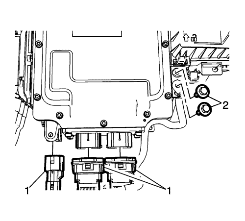
- Disconnect the electrical connectors (1).
- Remove the shield circuit harness earth fasteners (2) and reposition the earth cables.
- Disconnect the coolant pipes from the power inverter module. Refer to Drive Motor Power Inverter Module Cooling Inlet Hose Replacement and . Drive Motor Generator Control Module Radiator Outlet Hose Replacement .
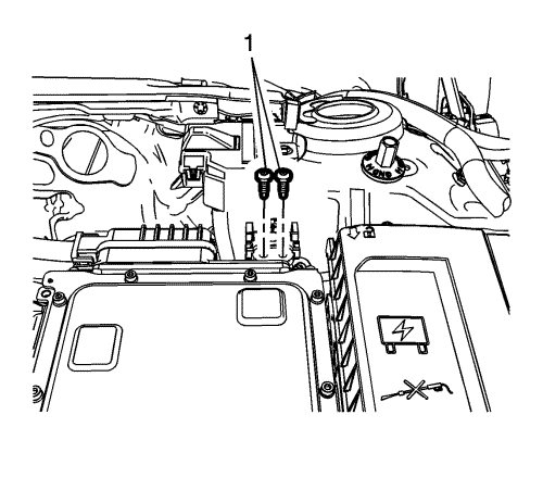
- Remove the high-voltage interlock loop connector fasteners (1) and reposition the connector.
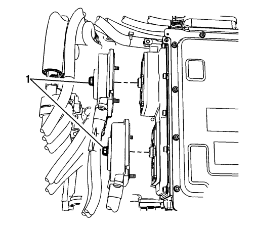
- Remove the three-phase cable fasteners (1) and reposition the cables.
- Discard the cable housing seals and the cable fastener seals.
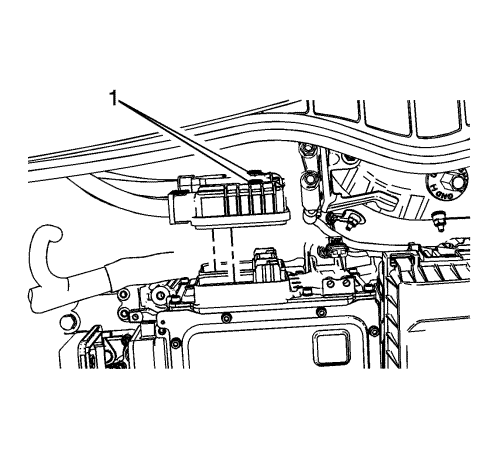
- Remove the 300 volt cable fasteners (1) and reposition the cables.
Note: The top cable should already be removed when the high-voltage disabling was performed.
- Discard the 300 volt cable connector seals.
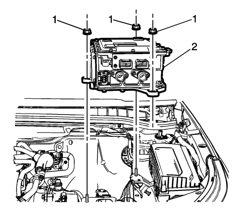
- Remove the power inverter fasteners (1) and drive motor power inverter control module (2).
Note: Replacement power inverter module comes pre-assembled with new coolant fittings. Replace coolant fittings only if necessary.
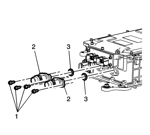
- Remove the coolant fitting fasteners (1) , the coolant fittings (2), and use NEW seals (3).
Installation Procedure
Note: It is possible to install the coolant fittings 180° out of position. Ensure the larger alignment tab is facing downwards.
- Install NEW coolant tube seals (3) and the coolant fittings (2).
- Tighten the coolant tube fasteners to 3 N·m (27 lb in).
Caution: Refer to Fastener Caution in the Preface section.
- Install the drive motor power inverter control module (2) and tighten the fasteners (1) to 9 N·m (80 lb in).
Note: Start the 300 volt cable fasteners by hand.
- Install the 300 volt cables with NEW seals and tighten the fasteners (1) to 9 N·m (80 lb in).
- With NEW connector housing and fastener seals, install the three-phase cables and tighten the fasteners (1) to 9 N·m (80 lb in).
- Install the high-voltage interlock loop connector fasteners (1) and tighten to 6 N·m (53 lb in).
- Connect the coolant pipes to the power inverter module. Refer to Drive Motor Power Inverter Module Cooling Inlet Hose Replacement and . Drive Motor Generator Control Module Radiator Outlet Hose Replacement .
- Fill the cooling system. Refer to Drive Motor Generator Power Inverter Module Cooling System Draining and Filling .
- Install the ground strap fasteners (2) and tighten to 9 N·m(80 lb in).
- Connect the electrical connectors (1).
- Install the power inverter module cover. Refer to Drive Motor Generator Power Inverter Module Cover Replacement .
- Enable the high-voltage system. Refer to High-Voltage Enabling .
- For control module programming and set-up procedures, refer to Control Module References .
| ©© Copyright Chevrolet. All rights reserved |


