SECTION
MAINTENANCE AND REPAIR
ON-VEHICLE SERVICE
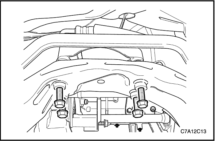


Rack and Pinion Assembly
Removal Procedure
- Raise and suitably support the vehicle.
- Remove the exhaust front pipe. According to engine type, refer to Section 1G1 or 1G2, 1G3 Engine Exhaust.
- Remove the transaxle rear mount assembly. According to engine type, refer to Section 1B or 1C1. 1C2 Engine Mechanical.
- For AWD, remove the transfer case. Refer to Section 5D, Transfer Case.


- Disconnect the negative battery cable.
- Raise and suitably support the vehicle.
- Remove the wheels. Refer to Section 2E, Tires and Wheels.
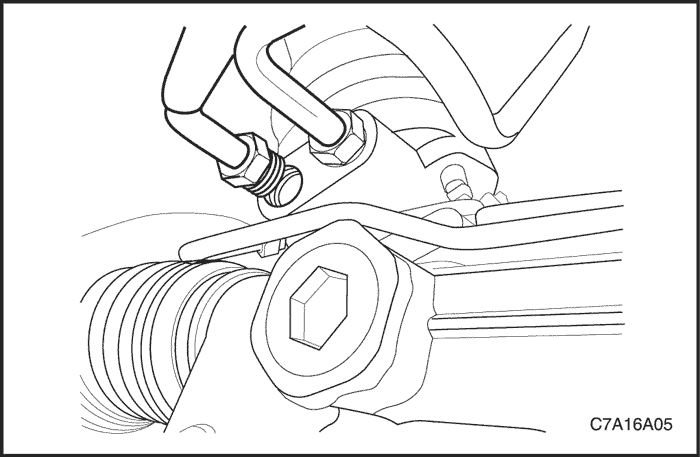
- Disconnect the power steering gear fluid inlet pipe.
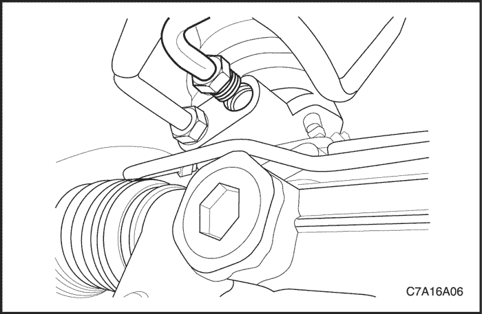


- Disconnect the power steering gear fluid outlet pipe. Place a drain pan under the steering gear to catch the power steering fluid.


- Rotate the steering wheel in order to gain access to the intermediate shaft pinch bolt.
- Disconnect the connector of SSPS, if equipped.
- Scribe a mark on the stub shaft housing that lines up with a mark on the intermediate shaft lower coupling.
- Remove the intermediate shaft pinch bolt.
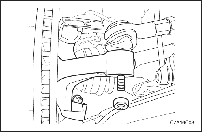


- Remove the outer tie rod nuts and disconnect the tie rod ends from the steering knuckle.
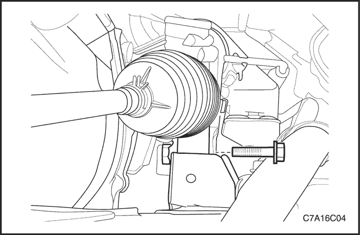


- Remove the left mounting bolt from the steering gear.
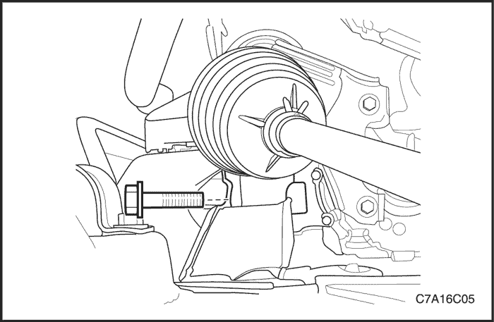


- Remove the right mounting bolt from steering gear.
- Remove the rack and pinion assembly from the vehicle.
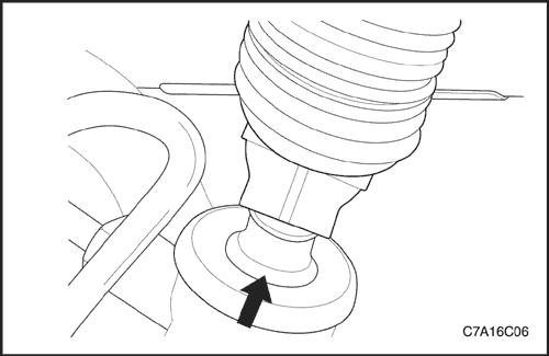


Installation Procedure
- Install the rack and pinion assembly from below. The steering gear must be in a straight-ahead position, and the steering wheel spokes must be vertical and pointing to the left. Align the marks on the shafts to ensure proper positioning. Seat the stub shaft into the intermediate shaft.


- Install the left and right mounting bolts on the steering gear.
Tighten
Tighten the steering gear mounting bracket bolts and nuts to 110 N•m (81 lb-ft).


- Connect the tie rod ends to the steering knuckle.
- Install the outer tie rod nuts.
Tighten
Tighten the outer tie rod nuts to 50 N•m (37 lb-ft).


- Install the lower intermediate shaft pinch bolt.
Tighten
Tighten the intermediate shaft pinch bolt to 34 N•m (25 lb-ft).


- Connect the power steering gear fluid inlet pipe.
Tighten
Tighten the steering gear inlet pipe fitting to 28 N•m (21 lb-ft).


- Connect the power steering gear fluid outlet pipe.
Tighten
Tighten the steering gear outlet pipe fitting to 28 N•m (21 lb-ft).


- For AWD, install the transfer case. Refer to Section 5D, Transfer Case.
- Install the transaxle rear mount assembly. According to engine type, refer to Section 1B or 1C1. 1C2 Engine Mechanical.
- Install the exhaust front pipe. According to engine type, refer to Section 1G1 or 1G2, 1G3 Engine Exhaust.
- Install the wheels. Refer to Section 2E, Tires and Wheels.
- Lower the vehicle.
- Do a straight-ahead check. Refer to "Straight-Ahead Check" in this section.
Notice : When adding fluid or making a complete fluid change, always use power steering fluid DEXRON®-IID. Failure to use the proper fluid will cause hose and seal damage and fluid leaks.
- Refill the power steering system and check for leaks. If leaks are found, correct the cause of the leak and bleed the system. Refer to Section 6A, Power Steering System.
- Connect the negative battery cable.


Outer Tie Rod
Removal Procedure
- Remove the wheel. Refer to Section 2E, Tires and Wheels.
- Mark the threads on the inner tie rod to aid in repositioning the adjusting nut.
- Remove the outer tie rod nut and disconnect the outer tie rod from the steering knuckle.
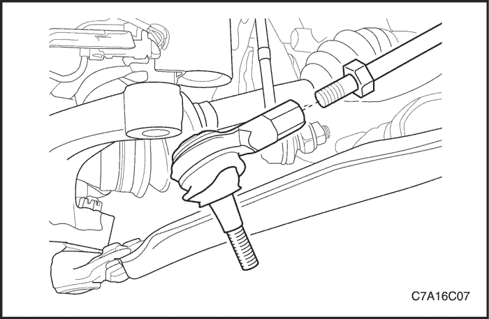


- Loosen the outer tie rod adjusting nut and remove the outer tie rod by twisting it off the inner tie rod.


Installation Procedure
- Reposition the adjusting nut to the marks on the inner tie rod.
- Install the outer tie rod by twisting it onto the inner tie rod.


- Connect the outer tie rod to the steering knuckle.
- Perform a front toe adjustment. Refer to Section 2B, Wheel Alignment.
- Tighten the adjusting nut.
Tighten
Tighten the outer tie rod adjusting nut to 60 N•m (44 lb-ft).
- Install the outer tie rod nut.
Tighten
Tighten the outer tie rod nut to 50 N•m (37 lb-ft).
- Install the wheel. Refer to Section 2E, Tires and Wheels.


Dust Boot
Tools Required
Removal Procedure
- Raise and suitably support the vehicle
- Remove rack and pinion assembly from the vehicle. Refer to "Rack and Pinion Assembly" in this section.
- Remove the outer tie rod. Refer to "Outer Tie Rod" in this section.
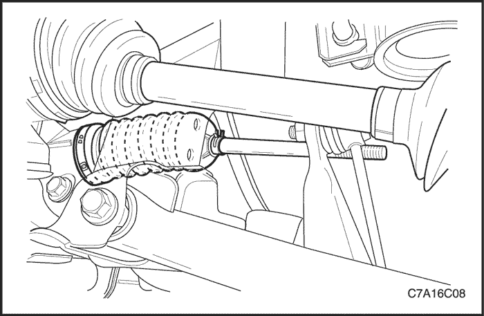
- Remove the dust boot outer retaining clamps.
- Cut and remove the dust boot inner retaining clamps.
- Remove the dust boot.


Installation Procedure
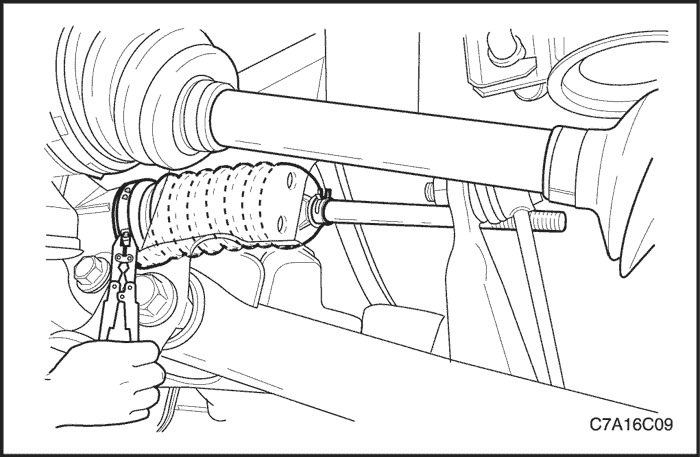
- Install the dust boot.
- Install the dust boot outer retaining clamp. Install the dust boot inner retaining clamp with the installer KM-J-22610.
- Install the outer tie rod. Refer to "Outer Tie Rod" in this section.
- Install the rack and pinion assembly. Refer to "Rack and Pinion Assembly" in this section.
- Lower the vehicle.


Straight-Ahead Check
After completing all the necessary operations on the steering gear, such as removing and installing, disassembling and assembling, check the exact straight-ahead position of the steering in each case.
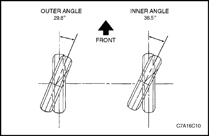
With the vehicle on the floor, place the steering wheel in the straight-ahead position. Mark the centerline of both tires on the floor. Turn the steering wheel all the way to the right and mark the new centerline of both tires on the floor.
Straight-Ahead Check Table
| Step | Action | Value(s) | Yes | No |
| 1 | Place the steering wheel in the straight-ahead position. Is the wheel in the correct position? | - | Go to Step 2 | - |
| 2 | Is the lower intermediate shaft pinch bolt lying parallel to the steering gear? | - | Go to Step 3 | Go to Step 4 |
| 3 | Is the steering wheel off center by more than 5 degrees? | - | Go to Step 5 | Go to Step 6 |
| 4 | The pinion is displaced on the rack. The steering pinion position must be corrected. Is the repair complete? | - | Go to Step 2 | - |
| 5 | Remove steering wheel and center it on the spindle splines. Is the repair complete? | - | Go to Step 3 | - |
| 6 | Turn the steering wheel all the way to the right. Measure the inner and the outer angles of the tire centerline compared to the straight-ahead centerline. Are the angles within specifications? | Inner angle: ≈ 36.5° Outer angle: ≈ 29.8° | System OK | Go to Step 7 |
| 7 | The rack assembly was not assembled correctly. Repair, as needed. Is the repair complete? | - | Go to Step 6 | - |


Intermediate Shaft, Joint and Dash Seal
Removal Procedure
- Turn the steering wheel until it is horizontal, with the spokes pointing down. This is the straight-ahead position. Make a mark on the stub shaft housing that lines up with the groove of the intermediate shaft. This mark will be used for proper alignment during installation.
- Remove the left front wheel. Refer to Section 2E, Tires and Wheels.
- Remove the lower pinch bolt from the universal joint on the steering gear.
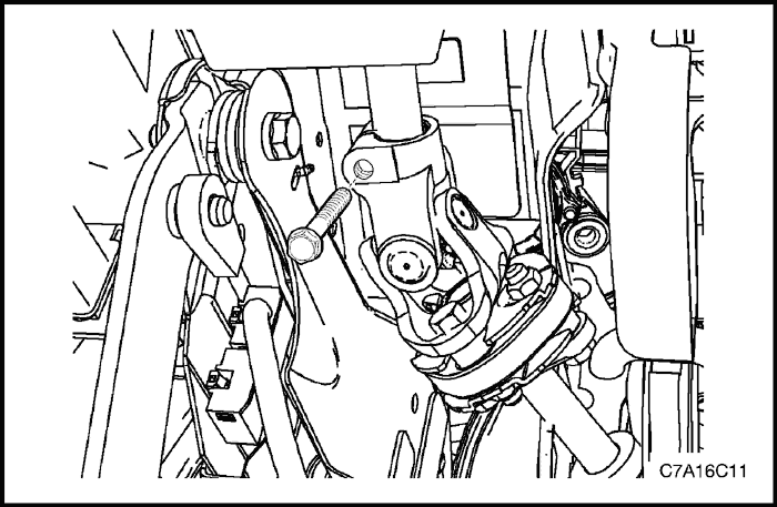


- Remove the upper pinch bolt from the universal joint on the intermediate shaft.
- Remove the intermediate shaft and dash seal.


Installation Procedure
- Install the intermediate shaft and dash seal into the vehicle.
Important : When attaching the upper universal joint, the steering wheel must be placed in the straight-ahead position with the spokes pointing down.
- Attach the universal joint of the intermediate shaft onto the steering column.
- Install the pinch bolts into the universal joint on the intermediate shaft and tighten the bolts.
Tighten
Tighten the intermediate shaft pinch bolts to 34 N•m (25 lb-ft).


Important : When attaching the lower universal joint, the marks on the intermediate shaft and on the stub shaft should line up.
- Attach the intermediate shaft onto the steering gear stub shaft.
Important : When installing the lower intermediate shaft pinch bolt, make sure the bolt goes through the universal joint on the side of the stub shaft with the notch. If you have trouble seating the universal joint completely down onto the stub shaft, rotate the steering wheel slightly while pushing down on the universal joint.
- Install the bolt into the lower universal joint on the intermediate shaft and tighten the bolt.
Tighten
Tighten the intermediate shaft pinch bolt to 34 N•m (25 lb-ft).


Hydraulic Cylinder Lines
Removal Procedure
- Raise and suitably support the vehicle.
- Remove the exhaust front pipe. According to engine type, refer to Section 1G1 or 1G2, 1G3 Engine Exhaust.
- Remove the transaxle rear mount assembly. According to engine type, refer to Section 1B or 1C1. 1C2 Engine Mechanical.
- For AWD, remove the transfer case. Refer to Section 5D, Transfer Case.
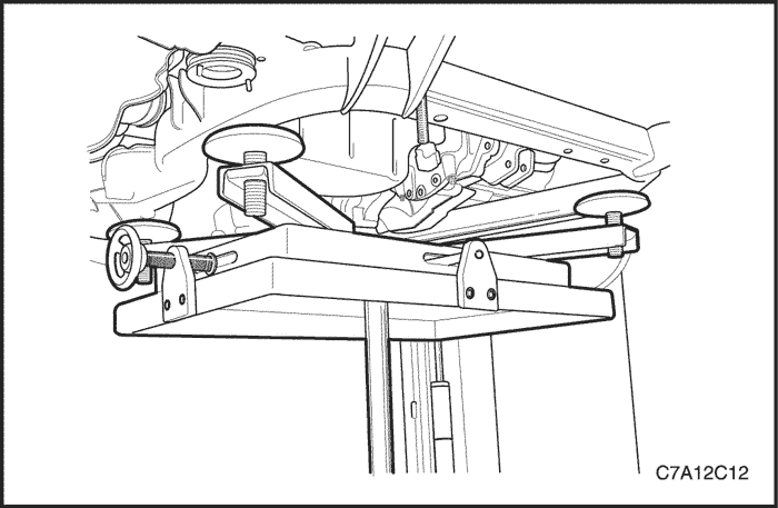


- Siphon the power steering fluid from the fluid reservoir.
- Disconnect the power steering gear hydraulic cylinder pipes from the power steering gear at the valve end. Replace the O-ring seals, as needed.
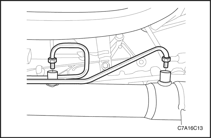


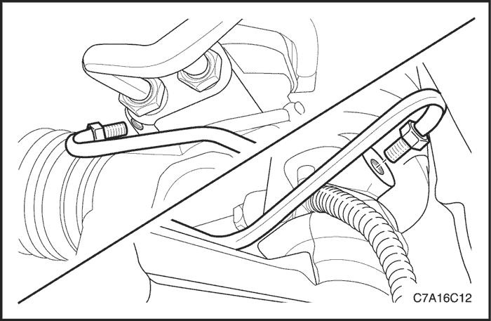
- Disconnect the power steering gear hydraulic cylinder pipes from the power steering gear at the cylinder end.
- Remove the steering gear hydraulic cylinder pipes from the vehicle.


Installation Procedure
- Lubricate any new O-ring seals with power steering fluid.
- Place the O-ring seals into the housing and install the steering gear hydraulic cylinder pipes.
- Connect the power steering gear hydraulic cylinder pipes to the power steering gear at the valve end.
Tighten
Tighten the hydraulic cylinder line fittings at the valve end to 19 N•m (14 lb-ft).


- Connect the power steering gear hydraulic cylinder pipes to the power steering gear at the cylinder end.
Tighten
Tighten the hydraulic cylinder line fittings at the cylinder end to 19 N•m (14 lb-ft).
- Lower the vehicle.


- For AWD, install the transfer case. Refer to Section 5D, Transfer Case.
- Install the transaxle rear mount assembly. According to engine type, refer to Section 1B or 1C1. 1C2 Engine Mechanical.
- Install the exhaust front pipe. According to engine type, refer to Section 1G1 or 1G2, 1G3 Engine Exhaust.
Notice : When adding fluid or making a complete change, always use DEXRON®-IID power steering fluid. Failure to use the proper fluid will cause hose and seal damage and fluid leaks.
- Fill the fluid reservoir with power steering fluid.
- Inspect for leaks. If there are leaks, correct the cause of the leaks and bleed the system. Refer to "Bleeding the Power Steering System" in this section.


Speed Sensitive Power Steering (SSPS) Control Module
Removal Procedure
- Disconnect negative battery cable.
- Remove the driver inee bolster. Refer to Section 9G, Interior Trim.
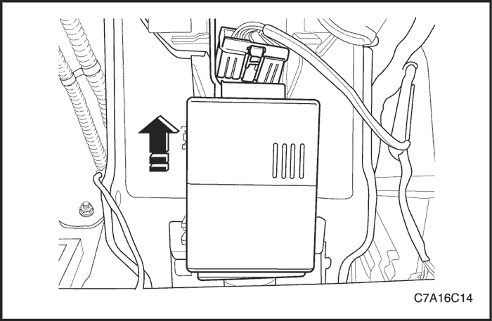
- Disconnect the connector of SSPS control module.
- Remove the SSPS control module from the bracket by sliding the control module upward.
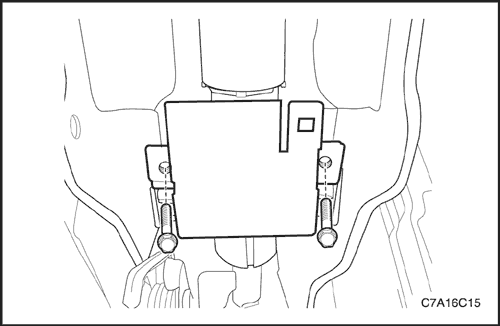


- Remove the bracket by removing the bolts, if needed.


Installation Procedure
- Install the control module bracket with bolts.
Tighten
Tighten the SSPS control module bracket bolts to 10 N•m (7 lb-ft).
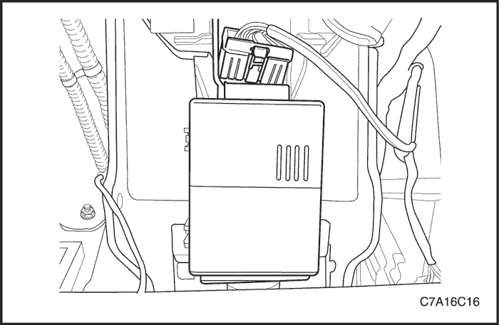


- Install the SSPS control module on the bracket.
- Connect the connector of SSPS control module.
- Install the driver knee bolster. Refer to Section 9G, Interior Trim.
- Connect the negative battery cable.
GENERAL DESCRIPTION AND SYSTEM OPERATION
Power Rack and Pinion
The power rack and pinion steering system has a rotary control valve that directs hydraulic fluid coming from the hydraulic pump to one side or the other side of the rack piston. The integral rack piston is attached to the rack. The rack piston converts hydraulic pressure to a linear force that moves the rack left or right. That force is then transmitted through the tie rods to the steering knuckles, which turn the wheels.
If power rack and pinion steering is not available, manual rack and pinion control is used; however, with this system, more steering effort is required. The movement of the steering wheel is transferred to the pinion. The rotary movement of the pinion is then transferred through the pinion threads, which mesh with teeth on the rack, thereby causing the rack to move in a linear direction.
A vane-type of hydraulic pump provides hydraulic pressure for both steering systems.
Speed Sensitive Power Steering System
The speed sensitive power steering (SSPS) system varies the driver effort required to steer as the vehicle speed changes. At low speeds, the system provides maximum power assist for easy turning and parking maneuvers. At higher speeds, the steering power is reduced to provide the driver with firmer steering and directional stability. The SSPS system accomplishes this by controlling the current (-3 ~ 3A) that is supplied into the magnetic coil equipped in power steering gear as the vehicle speed increases. When the vehicle is stationary, the SSPS system provides maximum steering assist the steering gear. As the vehicle speed increases, the steering assist to the steering gear is decreased.
Control Module
The SSPS control module processes the vehicle speed information from the ABS control module to the magnetic coil located on the power steering gear assembly.
Power Rack and Pinion
Except for differences in valve machining, the design of the SSPS power rack and pinion assembly is the same as for the a non-SSPS system. The steering wheel movement is transferred to the pinion via the intermediate shaft. The pinion moves the rack left or right through meshing the pinion and the rack teeth. The force is then transmitted through the tie rods and steering knuckle to steer the wheels.
The power rack and pinion steering system has a rotary control valve which directs the hydraulic fluid from the power steering pump to one side or the other side of the rack piston. The piston is attached to the rack and uses hydraulic pressure to move the rack left or right. The rotary control valve regulates the degree of assist by responding to the driver's torque input.
If hydraulic assist is not available, manual control is maintained. However, under this condition, more steering effort is required.
Power Steering Pump
The standard vane-type pump, which provides hydraulic pressure for the system.
System Operation
System operation originates with input from the vehicle speed via the ABS module to the SSPS control module. The SSPS control module sends a signal to the SSPS actuator to vary the rate of reaction force output by the magnetic coil.
Circuit Operation
The SSPS system uses inputs from the ABS module to the SSPS control module to determine the desired amount of power steering assist.
The SSPS control module constantly compares the amount of current flowing through the SSPS actuator to the desired current it has calculated.The SSPS actuator has magnetic coil that can control the reaction force supplied to steering torsion bar. The SSPS control module can change the amount of current flowing through the SSPS actuator by varying the output duty cycle.
The SSPS control module has the ability to detect faults in the itself, the SSPS actuator, or the circuitry to those components. Any default detected will cause the power steering assist to remain at maximum with the pintle in its normally retracted position for all speeds.
When the system is operating normally, increasing the vehicle speed will decrease power steering assist, allowing the driver to have improved road feel and directional stability.


