To the top of the document
Aveo
To Previous Page To Next Page
GMDE Start Page Load static TOC Load dynamic TOC Help?


T8B52C15
Display graphicTranslations of text in graphics


Cylinder Head and Gasket

Removal Procedure

  1. Disconnect the negative battery cable.
  2. Drain the engine coolant. Refer to Section 1D, Engine Cooling.
  3. Relieve the fuel pressure. Refer to Section 1F1, Engine Ccontrols.
  4. Remove the cylinder Head cover. Refer to “Cylinder Head Cover" in this section.


  5. T8B52C17
    Display graphicTranslations of text in graphics


  6. Remove the timing chain cover. Refer to “Timing Chain System" in this section.


  7. T8B52C18
    Display graphicTranslations of text in graphics


  8. Remove the camshaft. Refer to “Camshaft” in this section.


  9. T8B52C13
    Display graphicTranslations of text in graphics


  10. Remove the intake manifold. Refer to “Intake Manifold” in this section.


  11. T8B52C14
    Display graphicTranslations of text in graphics


  12. Remove the exhaust manifold. Refer to “Exhaust Manifold" in this section.


  13. T8B52C19
    Display graphicTranslations of text in graphics


  14. Remove the cylinder head bolts.
  15. Remove the cylinder head with the gasket.

Cleaning

  1. Clean the cylinder head sealing surface.
  2. Clean the cylinder block sealing surface.
  3. Clean the cylinder head cover bolts.
  4. Clean the cylinder head cover bolt holes.


T8B52C19
Display graphicTranslations of text in graphics


Installation Procedure

  1. Install the cylinder head assembly and the NEW gasket.
  2. Tighten the cylinder head bolts.
  3. Tighten
    Cylinder Head Bolts : 22 N•m + 82°


    T8B52C14
    Display graphicTranslations of text in graphics


  4. Install the exhaust manifold. Refer to “Exhaust Manifold" in this section.


  5. T8B52C13
    Display graphicTranslations of text in graphics


  6. Install the intake manifold. Refer to “Intake Manifold" in this section.


  7. T8B52C18
    Display graphicTranslations of text in graphics


  8. Install the camshaft. Refer to “Camshaft" in this section.


  9. T8B52C18
    Display graphicTranslations of text in graphics


  10. Install the timing chain. Refer to “Timing Chain System" in this section.


  11. T8B52C15
    Display graphicTranslations of text in graphics


  12. Install the cylinder Head cover. Refer to “Cylinder Head Cover" in this section.
  13. Refill the engine cooling system. Refer to Section 1D, Engine Cooling.
  14. Connect the negative battery cable.


T8B52G03
Display graphicTranslations of text in graphics


Oil Pan

Removal Procedure

    Caution : If the oil pan is deformed when removing it, do not use it and use a new oil pan.

  1. Disconnect the negative battery cable.
  2. Drain the engine oil.
  3. Remove the front exhaust pipe. Refer to Section 1G, Engine Exhaust.


  4. T8B52C16
    Display graphicTranslations of text in graphics


  5. Remove the oil pan retaining bolts.
  6. Remove the oil pan.
  7. Remove the gasket between the oil pan and the sealing surface of the engine block.


T8B52C16
Display graphicTranslations of text in graphics


Installation Procedure

  1. Apply the liquid gasket to the oil pan.
  2. Install the oil pan to the engine block and tighten the Oil Pan Retaining Bolts.
  3. Tighten
    Oil Pan Retaining Bolts : 10.5 N•m (7.7 lb-ft).


    T8B52G03
    Display graphicTranslations of text in graphics


  4. Install the front exhaust pipe. Refer to Section 1G, Engine Exhaust
  5. Refill the engine oil.


T8B52C15
Display graphicTranslations of text in graphics


Oil Pump

Tools Required

EN-49072 Installer-Crankshaft Front Seal

Removal Procedure

  1. Disconnect the negative battery cable.
  2. Remove the cylinder head cover. Refer to “Cylinder Head Cover" in this section.
  3. Remove the front exhaust pipe. Refer to Section 1G, Engine Exhaust.


  4. T8B52C37
    Display graphicTranslations of text in graphics


  5. Remove the oil pan. Refer to “Oil Pan" in this section.
  6. Remove the timing chain cover. Refer to “Timing Chain System" in this section.
  7. Remove the gasket between the oil pan and the sealing surface of the engine block.


  8. T8B52C39
    Display graphicTranslations of text in graphics


  9. Remove the oil pump retaining bolts from the timing chain cover.


T8B52C39
Display graphicTranslations of text in graphics


Installation Procedure

  1. Tighten the oil pump retaining bolts from the timing chain cover and install the oil pump.
  2. Tighten
    Oil Pump Cover Bolts : 10 N•m (7.4 lb-ft).

  3. Install the timing chain cover. Refer to “Timing Chain System" in this section.


  4. T8B52C39
    Display graphicTranslations of text in graphics


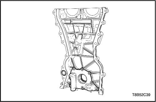
    Notice : If the crankshaft front oil seal is damaged, replace it with new oil seal. When installing the crankshaft front oil seal to the oil pump, make the oil seal groove faced toward the oil pump case contact.

  5. Install the crankshaft front oil seal using the installer(EN-49072).


  6. T8B52C37
    Display graphicTranslations of text in graphics


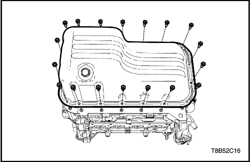
  7. Install the oil pan. Refer to “Oil Pan" in this section.
  8. Install the cylinder head cover. Refer to “Cylinder Head Cover" in this section.


  9. T8B52C15
    Display graphicTranslations of text in graphics


  10. Install the spark plug cable cover.
  11. Connect the negative battery cable.


S7B31C06
Display graphicTranslations of text in graphics


Engine Mount

Tools Required

DW110-060 Fixture-Engine Assembly Support

Removal Procedure

  1. Remove the air cleaner assembly. Refer to “Air Cleaner Assembly" in this section.
  2. Support the engine assembly using the engine assembly support fixture DW110-060.


  3. S7B31C07
    Display graphicTranslations of text in graphics


  4. Remove the engine mount bracket retaining bolts/nuts.


  5. S7B31C08
    Display graphicTranslations of text in graphics


  6. Remove the engine mount retaining bolts.
  7. Remove the engine mount assembly.


S7B31C08
Display graphicTranslations of text in graphics


Installation Procedure

  1. Install the engine mount assembly.
  2. Tighten the engine mount retaining bolts.
  3. Tighten
    Engine Mount Retaining Bolts : 55 N•m (40.5 lb-ft).


    S7B31C07
    Display graphicTranslations of text in graphics


  4. Tighten the engine mount bracket retaining bolts/nuts.
  5. Tighten
    Engine Mount Bracket Retaining Bolts/Nuts : 65 N•m (47.9 lb-ft).

  6. Remove the engine assembly support fixture DW110-060.
  7. Install the air cleaner assembly. Refer to “Air Cleaner Assembly" in this section.


T8B52C35
Display graphicTranslations of text in graphics


Engine Assembly

Tools Required

DW010-010 Engine & Transaxle Assembly Support Remover/Installer

Removal Procedure

  1. Discharge the air condition(A/C) system, if equipped.
  2. Drain the power steering oil, if equipped.
  3. Drain the engine coolant. Refer to Section 1D, Engine Cooling.
  4. Remove the battery and battery tray. Refer to Section 1E, Engine Electrical.
  5. Remove the air cleaner assembly. Refer to “Air Cleaner Assembly" in this section.


  6. T8B52C63
    Display graphicTranslations of text in graphics


  7. Disconnect the radiator inlet and outlet hose.
  8. Disconnect the heater core inlet and outlet hose.


  9. T8B58B05
    Display graphicTranslations of text in graphics


  10. Remove the power steering hose from the power steering pump. Refer to Section 6B, Power Steering Pump.
  11. Remove the A/C compressor hose from the compressor. Refer to Section 7B, Manual Control Heating, Ventilation and Air Conditioning System.


  12. T3D11C11
    Display graphicTranslations of text in graphics


  13. Disconnect the accelerator cable.
  14. Disconnect the TPS connector.
  15. Disconnect the IACV connector.
  16. Disconnect the A/C pressure sensor connector.
  17. Disconnect the power steering oil pressure switch cable.


  18. T8B52C64
    Display graphicTranslations of text in graphics


  19. Disconnect the coolant temperature sensor connector.
  20. Disconnect the EGR valve connector.
  21. Disconnect the camshaft sensor connector.
  22. Disconnect the ignition coil connector.
  23. Disconnect the oxygen sensor connector.
  24. Disconnect the crank position sensor connector.


  25. T8B52C65
    Display graphicTranslations of text in graphics


  26. Disconnect the injector main connector.
  27. Disconnect the canister solenoid connector.
  28. Disconnect the VGIS solenoid connector.
  29. Disconnect the starter connector. Refer to Section 1E, Engine Electrical
  30. Disconnect the alternator connector. Refer to Section 1E, Engine Electrical


  31. K5B11B63
    Display graphicTranslations of text in graphics


  32. Remove the clutch cable and connectors. Refer to Section 5B, Five–Speed Manual Transaxle, if manual–transaxle.
  33. Remove the shift control cable from the auto–transaxle. Refer to Section 5A, AISIN Automatic Transaxle, if auto–transaxle.


  34. T4B31C06
    Display graphicTranslations of text in graphics


  35. Support the engine assembly using the engine assembly support fixture DW010-010.


  36. S7B31C07
    Display graphicTranslations of text in graphics


  37. Remove the engine mount bracket. Refer to “Engine Mount” in this section.
  38. Remove the transaxle mount bracket.


  39. S7B52C12
    Display graphicTranslations of text in graphics


  40. Remove the transaxle rear mount.


  41. T8B52C40
    Display graphicTranslations of text in graphics


  42. Remove the engine assembly.
  43. Remove the transmission from the engine assembly.


  44. T8B52C24
    Display graphicTranslations of text in graphics


  45. Remove the flywheel(manual transmission) or flexible plate(auto transmission).


T8B52C24
Display graphicTranslations of text in graphics


Installation Procedure

  1. Install the flywheel(manual transmission) or flexible plate(auto transmission).
  2. Tighten
    Flywheel/Flexible Plate Bolts : 45 N•m (33.2 lb-ft).


    T8B52C40
    Display graphicTranslations of text in graphics


  3. Install the transmission to the engine assembly.
  4. Tighten
    Transmission Assembly Blots (M/T & A/T) : 60 N•m (44.2 lb-ft).


    T4B31C06
    Display graphicTranslations of text in graphics


  5. Support the engine assembly using the engine assembly support fixture DW010-010.


  6. S7B31C07
    Display graphicTranslations of text in graphics


  7. Install the engine mount bracket. Refer to “Engine Mount” in this section.
  8. Install the transaxle mount bracket. Refer to “Engine Mount” in this section.


  9. S7B52C12
    Display graphicTranslations of text in graphics


  10. Install the transaxle rear mount.


  11. K5B11B63
    Display graphicTranslations of text in graphics


  12. Connect the clutch cable and connectors. Refer to Section 5B, Five–Speed Manual Transaxle, if manual–transaxle.
  13. Connect the shift control cable from the auto–transaxle. Refer to Section 5A, AISIN Automatic Transaxle, if auto–transaxle.


  14. T8B52C65
    Display graphicTranslations of text in graphics


  15. Connect the injector main connector.
  16. Connect the canister solenoid connector.
  17. Connect the VGIS solenoid connector.
  18. Connect the starter connector. Refer to Section 1E, Engine Electrical
  19. Connect the alternator connector. Refer to Section 1E, Engine Electrical


  20. T8B52C64
    Display graphicTranslations of text in graphics


  21. Connect the coolant temperature sensor connector.
  22. Connect the EGR valve connector.
  23. Connect the camshaft sensor connector.
  24. Connect the ignition coil connector.
  25. Connect the oxygen sensor connector.
  26. Connect the crank position sensor connector.


  27. T3D11C11
    Display graphicTranslations of text in graphics


  28. Connect the accelerator cable.
  29. Connect the TPS connector.
  30. Connect the IACV connector.
  31. Connect the A/C pressure sensor connector.
  32. Connect the power steering oil pressure switch cable.


  33. T8B58B05
    Display graphicTranslations of text in graphics


  34. Install the power steering hose from the power steering pump. Refer to Section 6B, Power Steering Pump.
  35. Install the A/C compressor hose from the compressor. Refer to Section 7B, Manual Control Heating, Ventilation and Air Conditioning System.


  36. T8B52C63
    Display graphicTranslations of text in graphics


  37. Connect the radiator inlet and outlet hose.
  38. Connect the heater core inlet and outlet hose.


  39. T8B52C35
    Display graphicTranslations of text in graphics


  40. Refill the engine coolant system. Refer to Section 1D, Engine Cooling.
  41. Install the battery and battery tray. Refer to Section 1E, Engine Electrical
  42. Install the air cleaner assembly. Refer to "Air Cleaner Assembly" in this section.


To Previous Page To Next Page
© Copyright Chevrolet Europe. All rights reserved