

Cylinder Head and Gasket
Removal Procedure
- Drain the engine coolant. Refer to Section 1D, Engine Cooling.
- Release the fuel pressure. Refer to Section 1F2, Engine Controls - 1.4 DOHC - G14D.
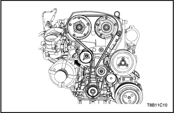
- Remove the timing belt. Refer to “Timing System”
in this section.
- Remove the timing belt tensioner. Refer to “Timing System”
in this section.
- Remove the camshaft. Refer to “Camshaft”
in this section.
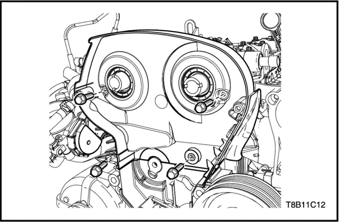
- Remove the timing belt rear cover.
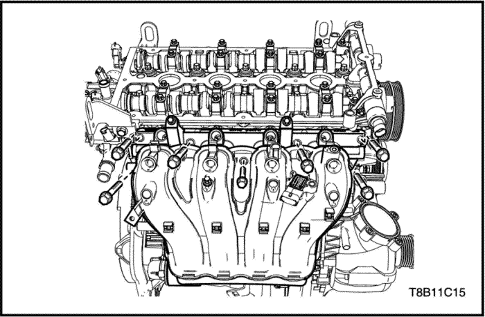
- Remove the intake manifold. Refer to “Intake Manifold”
in this section.
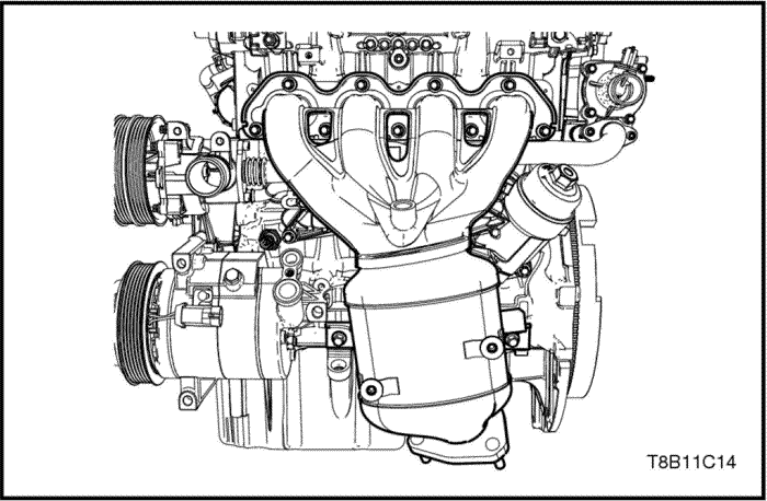
- Remove the exhaust manifold. Refer to “Exhaust Manifold"
in this section.
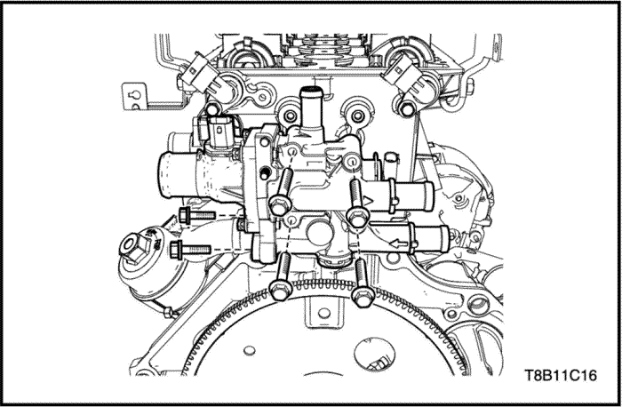
- Remove the coolant distributor. Refer to Section 1D, Engine Cooling.
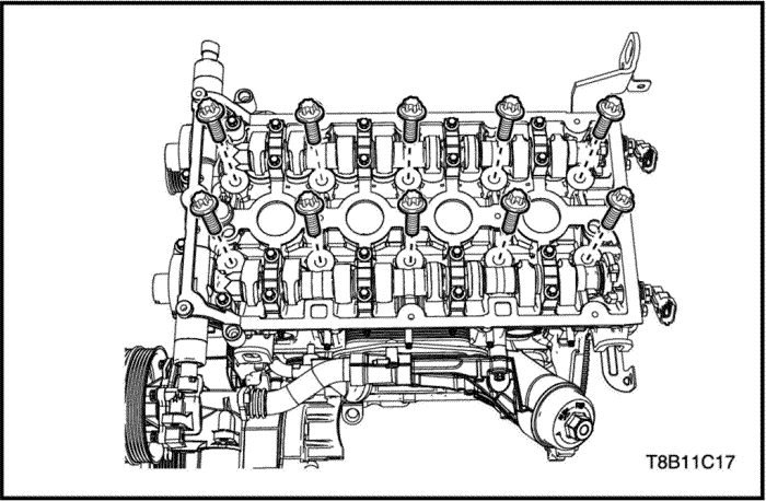
- Remove the cylinder head bolts.
- Remove the cylinder head with the gasket.
Installation Procedure
- Install the cylinder head with the new gasket.
- Install the cylinder head bolts.
Tighten
Tighten the cylinder head bolts to 25+90°+90°+90°+45° N•m (18.4+90°+90°+90°+45° lb-ft).
- Install the coolant distributor. Refer to Section 1D, Engine Cooling.
- Install the exhaust manifold. Refer to “Exhaust Manifold”
in this section.
- Install the intake manifold. Refer to “Intake Manifold"
in this section.
- Install the timing belt rear cover.
Tighten
Tighten the timing belt rear cover bolts to 6 N•m (53.1 lb-in).
- Install the camshaft. Refer to “Camshaft”
in this section.
- Adjust the belt timing. Refer to “Timing System-Adjustment”
in this section.
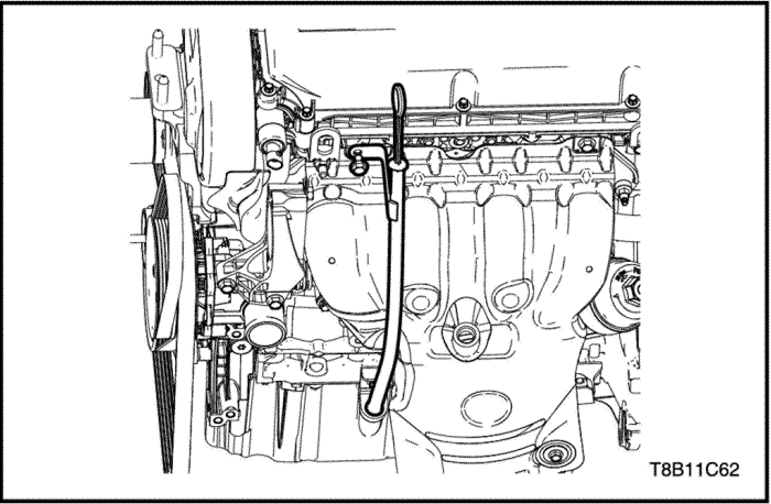
Oil Indicator and Tube
Removal and Installation Procedure
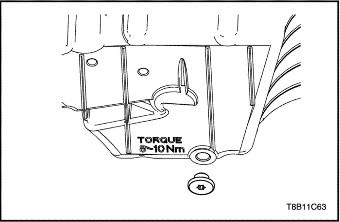
- Remove the oil indicator tube tightening bolt.
Tighten
Tighten the oil indicator tube tightening bolt to 10 N•m (7.3 lb-ft).
- Remove the oil indicator and tube.
Engine Oil and Filter Change
Removal Procedure
Caution : Do not accomplish this procedure when the engine is hot. It may cause damage and can be injured.
- Raise the vehicle.
- Locate the vessel for containing engine oil beneath drain plug of the vehicle.
- Remove the oil drain carefully.
- Drain the engine oil.
Notice : If the drain plug is damaged, replace a new one.
- Install the drain plug.
Tighten
Tighten the drain plug to 9 N•m (79.7 lb-in).
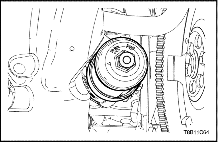
- Remove the oil filter cap.
- Remove the oil filter.
Installation Procedure
Notice : Do not re-use the engine oil filter.
- Install the new oil filter.
- Install the oil filter cap.
Tighten
Tighten the oil filter cap to 25 N•m (18.4 lb-ft).
Caution : Refer to engine oil specifications in OWNER’S MANUAL and refill the new suitable and recommended engine oil.
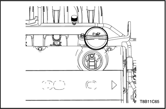
- Open the oil filling cap.
- Refill the new engine oil.
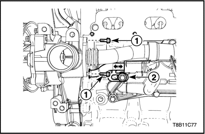
Oil Cooler
Removal Procedure
Caution : Do not accomplish this procedure when the engine is hot. It may cause damage and can be injured.
- Drain the engine coolant. Refer to Section 1D, Engine Cooling.
- Drain the engine oil. Refer to “Engine Oil and Filter Change”
in this section.
- Remove the exhaust manifold. Refer to “Exhaust Manifold”
in this section.
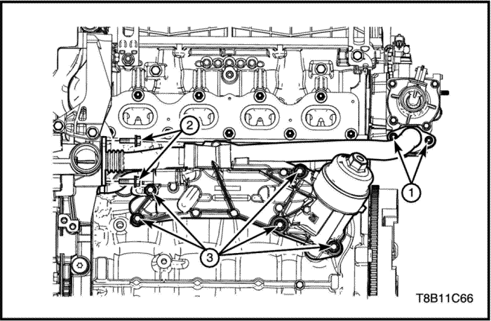
- Remove the coolant pipe bolts from the engine coolant distributor case(1).
- Remove the coolant pipe bolts from the engine front cover(2).
- Remove the oil cooler tightening bolts(3).
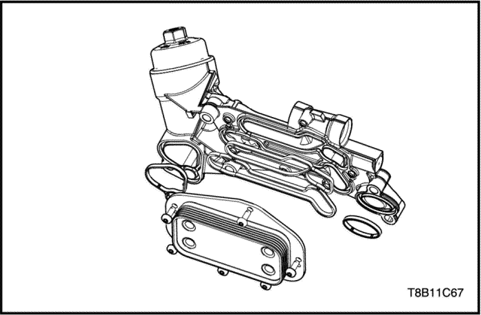
- Remove the heat exchanger with the gasket.
Installation Procedure
Caution : Check the damage or leakage on the oil cooler gaskets. If damage or leakage, replace the related gasket new one.
- Install the heat exchanger with the gasket to the oil cooler housing.
Tighten
Tighten the heat exchanger bolts to 8 N•m (70.8 lb-in).
- Insert the coolant pipes to the oil cooler housing with the gasket.
- Install the oil cooler tightening bolts(3).
Tighten
Tighten the oil cooler tightening bolts to 25 N•m (18.4 lb-ft).
- Install the coolant pipe bolts to the engine front cover(2).
Tighten
Tighten the coolant pipe bolts to 8 N•m (70.8 lb-in).
- Install the coolant pipe bolts to the engine coolant distributor case(1).
Tighten
Tighten the coolant pipe bolts to 8 N•m (70.8 lb-in).
- Remove the exhaust manifold. Refer to “Exhaust Manifold”
in this section.
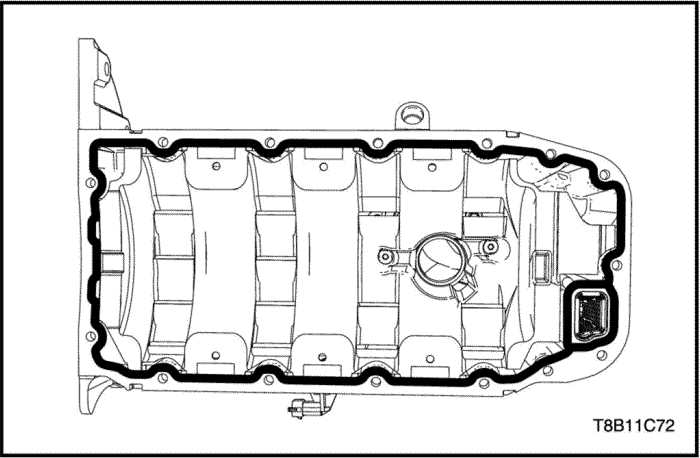
Oil Pan
Tools Required
Oil Pan Bolt Remover/Installer EN-49152
Removal Procedure
Caution : Do not accomplish this procedure when the engine is hot. It may cause damage and can be injured.
- Drain the engine oil. Refer to “Engine Oil and Filter Change”
in this section.
- Drain the engine oil.
- Remove the front exhaust pipe. Refer to Section 1G, Engine Exhaust.
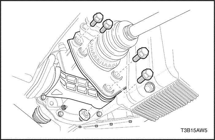
- Remove the transmission rear mounting bracket. (Auto transmission ONLY).
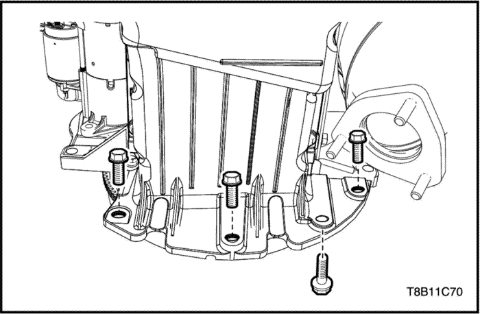
- Remove the oil pan-to-transmission bolts.
- Remove the oil pan bolts using by oil pan bolt remover/installer(EN-49152).
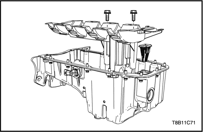
- Remove the oil pan baffle.
- Remove the oil suction filter.
Installation Procedure
- Remove the oil suction filter to the oil pan.
- Remove the oil pan baffle.
Tighten
Tighten the oil pan baffle bolts to 10 N•m (7.3 lb-ft).
- Clean the oil pan sealing surface.
- Apply the oil pan sealant(LOCTITE 5900) on the sealing surface.
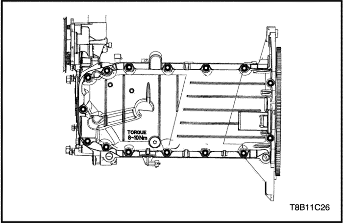
- Install the oil pan bolts using by oil pan bolt remover/installer(EN-49152).
Tighten
Tighten the oil pan bolts to 14 N•m (10.3 lb-ft).
- Install the oil pan-to-transmission bolts.
Tighten
Tighten the oil pan-to-transmission bolts to 40 N•m (29.5 lb-ft).
- Install the transmission rear mounting bracket. (Auto transmission ONLY).
Tighten
Tighten the transmission rear mounting bracket bolts and nut to 80 N•m (59 lb-ft).
Oil Pressure Relief Valve
Removal Procedure
- Remove the oil pan. Refer to “Oil Pan”
in this section.
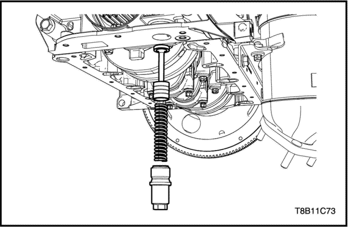
- Remove the oil pressure relief valve plug.
- Remove the valve spring.
- Remove the valve piston.
Installation Procedure
- Clean the plug thread, spring and piston.
- Install the valve piston.
- Install the valve spring.
- Install the oil pressure relief valve plug.
Tighten
Tighten the oil pressure relief valve plug to 21 N•m (15.5 lb-ft).
- Install the oil pan. Refer to “Oil Pan”
in this section.
Oil Overpressure Relief Valve
Removal Procedure
- Remove the oil pan. Refer to “Oil Pan”
in this section.
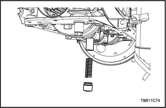
- Remove the oil overpressure relief valve plug.
- Remove the valve spring.
- Remove the valve piston.
Installation Procedure
- Clean the plug thread, spring and piston.
- Install the valve piston.
- Install the valve spring.
- Install the oil overpressure relief valve plug.
Tighten
Tighten the oil pressure relief valve plug to 10 N•m (88.5 lb-in).
- Install the oil pan. Refer to “Oil Pan”
in this section.
Oil Pump
Removal Procedure
Caution : Do not accomplish this procedure when the engine is hot. It may cause damage and can be injured.
- Drain the engine coolant. Refer to Section 1D, Engine Cooling.
- Drain the engine oil. Refer to “Engine Oil and Filter Change”
in this section.
- Remove the exhaust manifold. Refer to Section 1G, Engine Exhaust.
- Remove the timing belt. Refer to “Timing System”
in this section.
- Remove the oil pan. Refer to “Oil Pan”
in this section.
- Remove the power steering pump and bracket. Refer to Section 6B, Power Steering Pump.
- Remove the alternator. Refer to Section 1E, Engine Electrical.
- Remove the A/C compressor. Refer to Section 7B, HVAC System.
- Remove the engine coolant pipe(1) bolts.
- Remove the engine coolant pipe(2) bracket bolt and then push the pipe into the oil cooler housing.

- Remove the crankshaft sprocket.
- Remove the engine front cover assembly with the gasket.
Inspection
- Clean the measuring surface.
- Measure the axial clearance of rotors.
- If out-of-specifications, replace the new one. Refer to “Engine Specifications”
in this section.
Installation Procedure
Caution : Do not reuse the engine front cover gasket.
- Install the engine front cover assembly with the new gasket.
Tighten
Tighten the engine front cover assembly bolts to 20 N•m (14.7 lb-ft).
- Install the crankshaft sprocket.
- Install the engine coolant pipe(1) bolts.
- Install the engine coolant pipe(2) bracket bolt and then push the pipe into the oil cooler housing.
- Install the A/C compressor. Refer to Section 7B, HVAC System.
- Install the alternator. Refer to Section 1E, Engine Electrical.
- Install the power steering pump and bracket. Refer to Section 6B, Power Steering Pump.
- Install the oil pan. Refer to “Oil Pan”
in this section.
- Remove the timing belt. Refer to “Timing System”
in this section.
| © Copyright Chevrolet Europe. All rights reserved |


