UNIT REPAIR


Cylinder Head
Tools Required
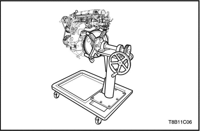
DW110-030 Engine Overhaul Stand
Removal Procedure
- Remove the engine assembly. Refer to “Engine Assembly”
in this section.
- Install the engine assembly to the DW110-030.
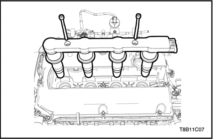
- Remove the ignition coil. Refer to Section 1F2, Engine Controls - 1.4 DOHC - G14D.
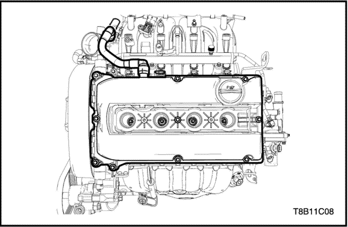
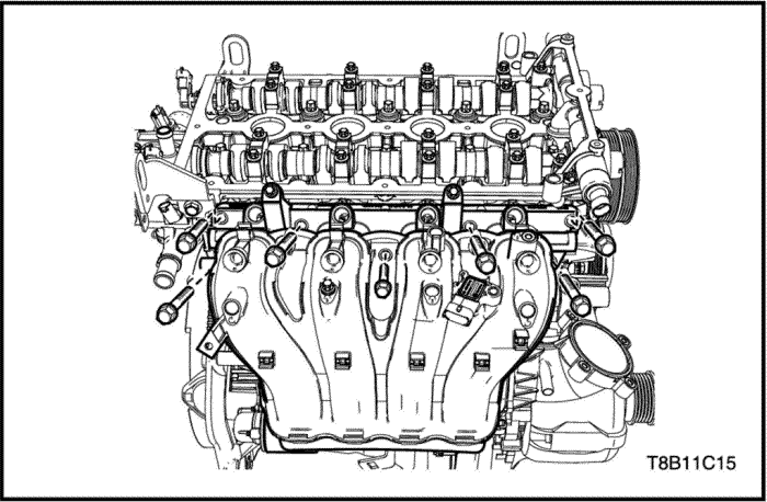
- Detach the PCV clips from the PCV hose.
- Remove the PCV hose from the cylinder head cover.
- Unscrew the cylinder head cover bolts.
- Remove the cylinder head cover.
- Remove the power steering pump and brakcet. Refer to Section 6B, Power Steering Pump.
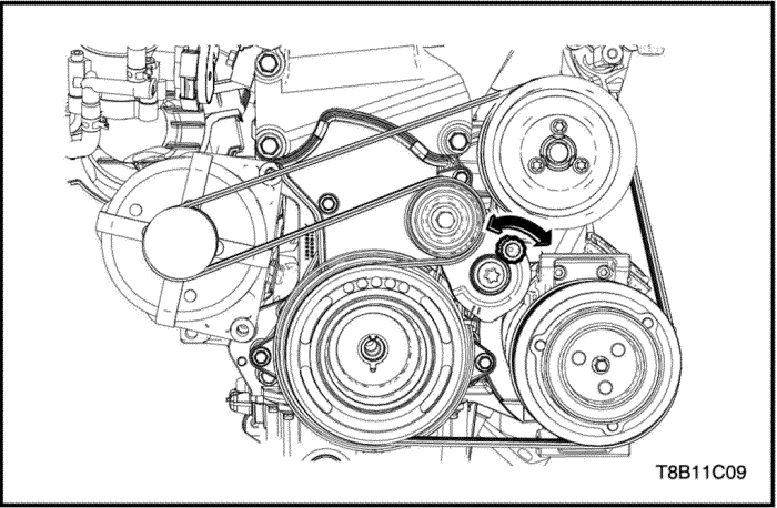
- Remove the power steering pump and brakcet. Refer to “Accessory Belt and Tensioner”
in this section.
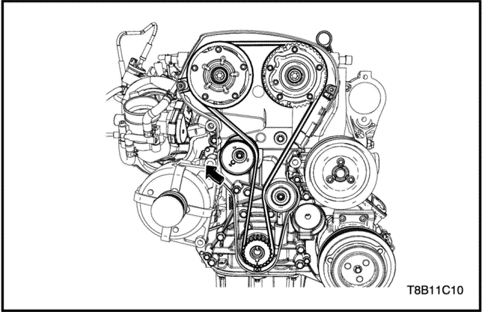
- Remove the timing belt. Refer to “Timing System”
in this section.
- Remove the timing belt tensioner. Refer to “Timing System”
in this section.
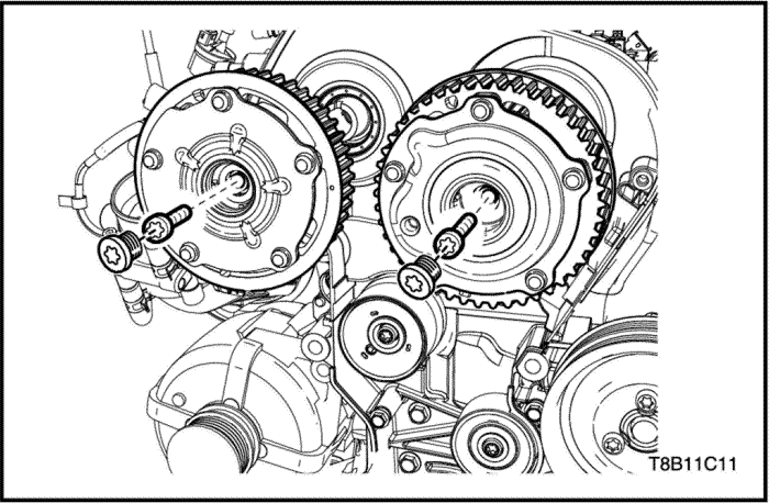
- Remove the camshaft sprocket. Refer to “Camshaft Sprocket”
in this section.
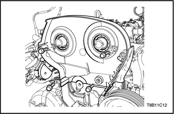
- Remove the camshaft rear cover.
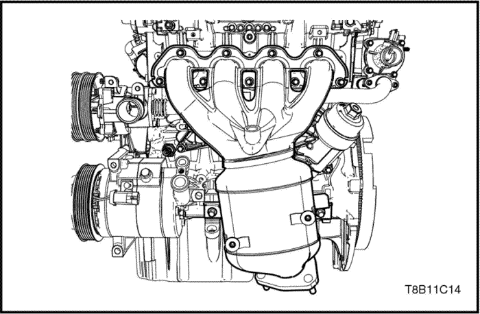
- Remove the exhaust manifold. Refer to “Exhaust Manifold”
in this section.
- Remove the throttle body. Refer to Section 1F2, Engine Controls - 1.4 DOHC - G14D.
- Remove the intake manifold. Refer to “Intake Manifold”
in this section.
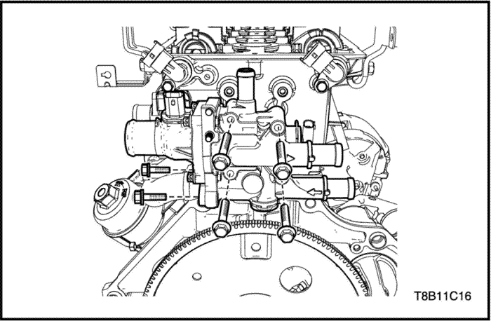
- Remove the engine coolant distributor. Refer to Section 1D2, Engine Cooling.
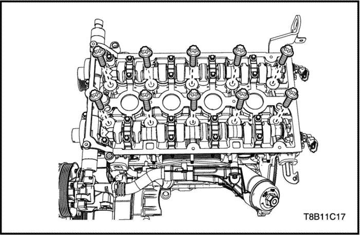
- Remove the cylinder head bolts.
- Remove the cylinder head assembly with the cylinder head gasket.
Inspection Procedure
Caution : Take extreme care to prevent any scratches, nicks or damage to the Cylinder Head Surface. If scratched, damage may happen to engine.
- Clean the sealing surfaces.
- Inspect the cylinder head for the following.
- Cracks, damage or pitting in the combustion chambers.
- Debris in the oil galleries. Continue to clean the galleries until all debris is removed.
- Coolant leaks or damage to the deck face sealing surface.
- Damage to any gasket surfaces.
- Damage to any threaded bolt holes.
- Burnt or eroded areas in the combustion chamber.
- Cracks in the exhaust ports and combustion chambers.
- External cracks in the water passages.
- Restrictions in the intake or exhaust passages.
- Restrictions in the cooling system passages.
- Rusted, damaged or leaking core plugs.
- If the cylinder head is cracked or damaged, it must be replaced. No welding or patching of the cylinder head is recommended.
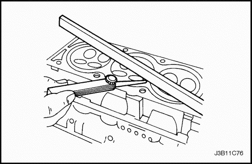
- Measure the clearance between the straight-edge and the cylinder head deck face using a feeler gauge at four points along the straight-edge.
- Check the sealing surfaces for deformation and warpage. The cylinder head sealing surfaces(include the intake and exhaust sealing surfaces) must be flat within the spec. Refer to the “Engine Specifications”
in this section.
- Remove the intake and exhaust camshafts. Refer to “Camshaft”
in this section.
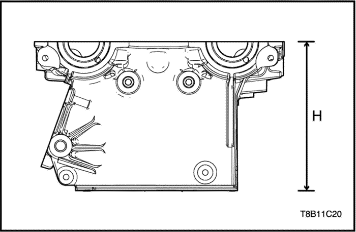
- Measure the height of the cylinder head from sealing surface to sealing surface. The cylinder head height should be in specifications, replace the cylinder head. If the cylinder head height is out of specifications, replace the cylinder head. Refer to the “Engine Specifications”
in this section.
Installation Procedure
Caution : Do not reuse the cylinder head gasket.
- Install the cylinder head assembly with the new cylinder head gasket.
- Install the cylinder head bolts.
Tighten
Tighten the cylinder head bolts to 25+90°+90°+90°+45° N•m (18.4+90°+90°+90°+45° lb-ft)
- Install the engine coolant distributor. Refer to Section 1D2, Engine Cooling.
- Install the intake manifold. Refer to “Intake Manifold”
in this section.
- Install the throttle body. Refer to Section 1F2, Engine Controls - 1.4 DOHC - G14D.
- Install the oil pan. Refer to “Exhaust Manifold”
in this section.
- Install the camshaft rear cover.
- Install timing belt system and adjust the timing. Refer to “Timing System”
in this section.
- Install the timing system. Refer to “Timing System”
in this section.
- Install the accessory belt. Refer to “Accessory Belt and Tensioner”
in this section.
- Install the power steering pump and brakcet. Refer to Section 6B, Power Steering Pump.
- Install the cylinder head cover.
- Screw the cylinder head cover bolts.
- Install the PCV hose from the cylinder head cover.
- Attach the PCV clips from the PCV hose.
- Install the ignition coil. Refer to Section 1F2, Engine Controls - 1.4 DOHC - G14D.
Camshaft
Tools Required
Removal Procedure
Caution : Take extreme care to prevent any scratches, nicks or damage to the camshaft surfaces. If scratched, damage may happen to engine.
- Remove the cylinder head. Refer to “UNIT REPAIR- Cylinder Head”
in this section.
- Remove the camshaft position solenoid valve housing.
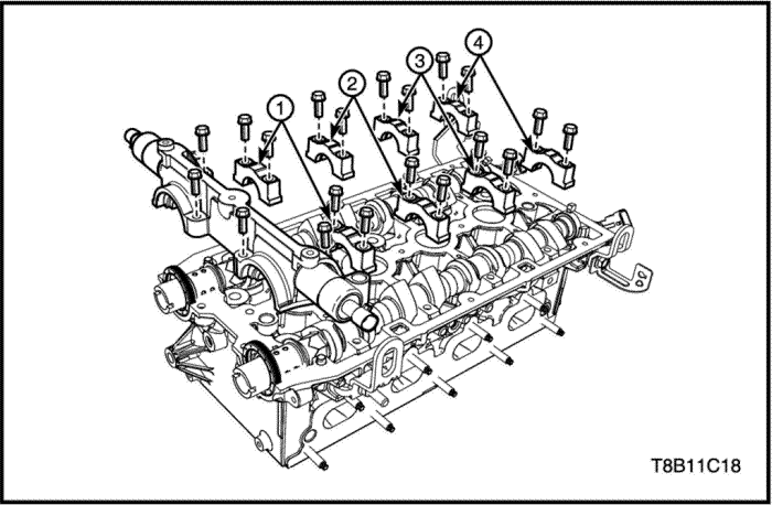
- Remove the camshaft cap bolts in this sequence (1)-(4)-(2)-(3).
- Remove the camshaft caps.
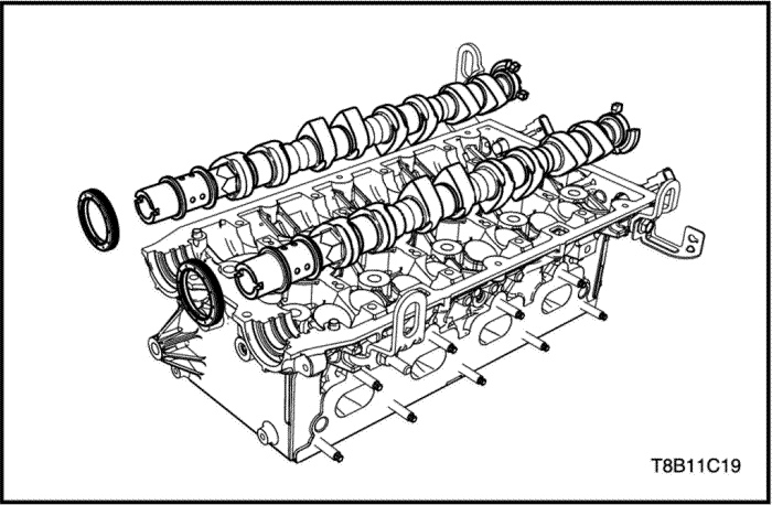
- Remove the camshafts and oil seal rings.
Inspection
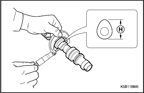
- Measure the camshaft lift(H). If it is out of specification, replace it. Refer to "Engine Specification"
in this section.
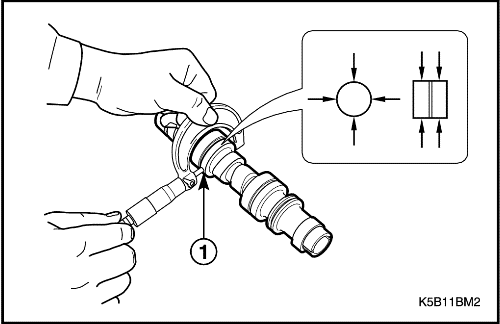
- Measure the camshaft journal outer diameter. If it is out of specification, replace it. Refer to "Engine Specification"
in this section.
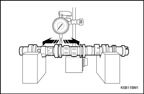
- Measure the camshaft bending value. If it is out of specification, replace it. Refer to "Engine Specification"
in this section.
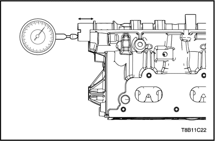
- Measure the camshaft end play. If it is out of specification, replace it. Refer to "Engine Specification"
in this section.
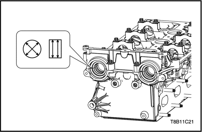
- Install the camshaft bearing cap to the cylinder head.
Tighten
Camshaft Cap Bolts to 8 N•m (70.8 lb-in).
- Measure the camshaft journal inner diameter. If it is out of specification, replace it. Refer to "Engine Specification"
in this section.
Installation Procedure
- Coat/Lubricate the camshaft bearing and cam surfaces with clean engine oil.
- Install the camshafts on the cylinder head.
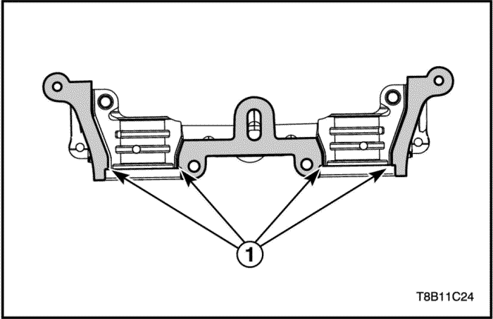
Important : It is essential to ensure that no sealant is applied outside the marked sealing areas.
- Apply surface sealant(LOCTITE 574) to sealing surfaces(1) of the 1st camshaft bearing cap thinly and evenly.
Notice : The grooves (1) adjacent to the sealing surfaces must remain free from sealant.
- Install the camshaft bearing caps in this sequence (2)-(3)-(1)-(4).
- Install the camshaft position solenoid valve housing.
Tighten
Tighten the camshaft bearing cap bolts to 8 N•m (70.8 lb-in).
- Install the new camshaft oil seal rings using by Installer(KM-422). Refer to “Camshaft Seal Ring”
in this section.
- Install the cylinder head assembly. Refer to "Unit Repair-Cylinder Head"
in this section.
| © Copyright Chevrolet Europe. All rights reserved |


