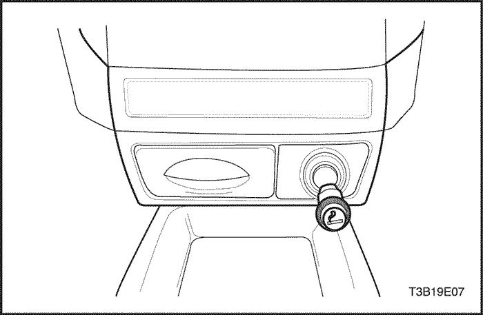
Install the cigar lighter in the cigar lighter housing.
Connect the negative battery cable.
Ashtray
Removal Procedure
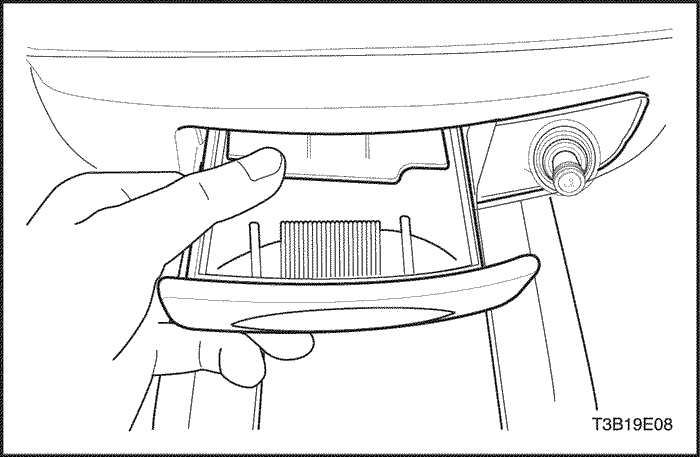
Remove the ashtray.
Installation Procedure
Install the ashtray.
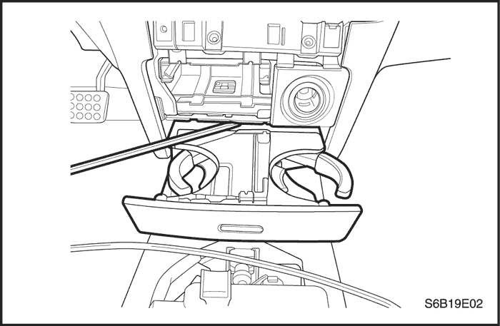
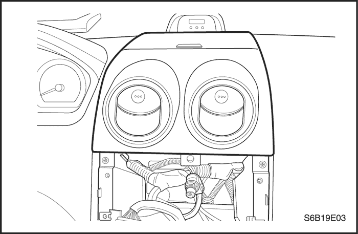
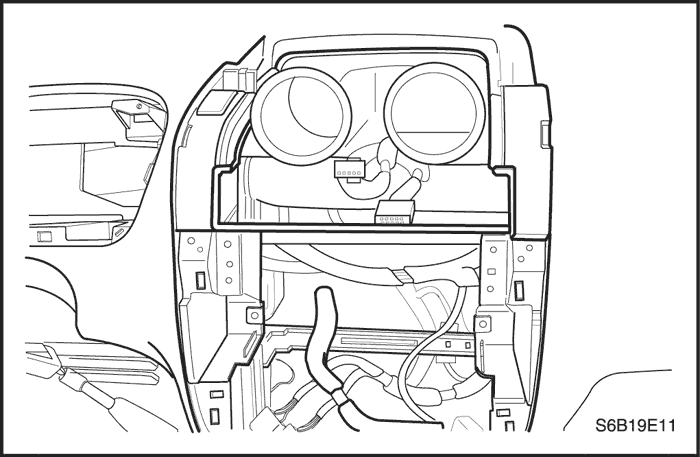
Cupholder
Removal Procedure
Remove the cupholder from the instrument panel.
Installation Procedure
Notice : Dissimilar metals in direct contact with each other may corrode rapidly. Make sure to use the correct fasteners to prevent premature corrosion.