SECTION 9O
BUMPERS AND FASCIAS
SPECIFICATIONS
Fastener Tightening Specifications
|
Application
|
N•m
|
Lb-Ft
|
Lb-In
|
|
Front Bumper Fascia Bolt
|
1.5
|
-
|
13
|
|
Front Bumper Fascia Screw
|
1.5
|
-
|
13
|
|
Front Bumper Impact Beam Nuts
|
24
|
18
|
-
|
|
Front Wheel Well Screws
|
1.5
|
-
|
13
|
|
Luggage Compartment Fascia Bolts, Nuts
|
4
|
-
|
35
|
|
Mud Guard Screws
|
1.5
|
-
|
13
|
|
Rear Bumper Energy Absorber Nuts
|
24
|
18
|
-
|
|
Rear Bumper Fascia Bolt
|
1.5
|
-
|
13
|
|
Rear Bumper Fascia Nut
|
25
|
-
|
18
|
|
Rear Bumper Fascia Screw
|
1.5
|
-
|
13
|
|
Rear Bumper Fascia-to-Lower Back Panel Nut
|
4
|
-
|
35
|
|
Rear Side Panel Trim Screw
|
1.5
|
-
|
13
|
|
Rear Upper Fascia Screws
|
1.5
|
-
|
13
|
|
Splash Shield Bolts
|
1.5
|
-
|
13
|
|
Splash Shield Nuts
|
1.5
|
-
|
13
|
|
Splash Shield Screws
|
1.5
|
-
|
13
|
MAINTENANCE AND REPAIR
On-Vehicle service
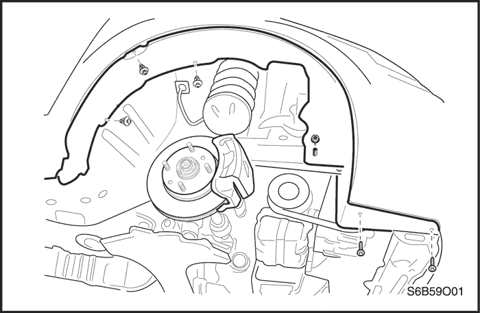


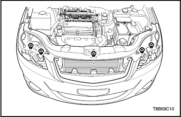
Front Bumper Fascia
Removal Procedure
- Disconnect the negative battery cable.
- Remove the front wheels. Refer to Section 2E, Tires and Wheels.
- Remove the screws, the bolts, the nuts, and the front wheel well splash shields.
- Remove the headlamps, the turn signal lamps, the side turn signal lamps and the front fog lamps. Refer to Section 9B, Lighting Systems.
- Remove the screws from underneath the fascia.
- Remove the nuts from the fascia
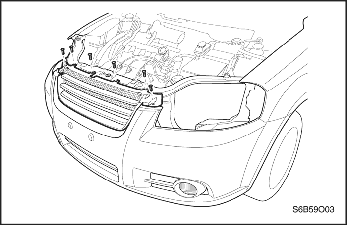
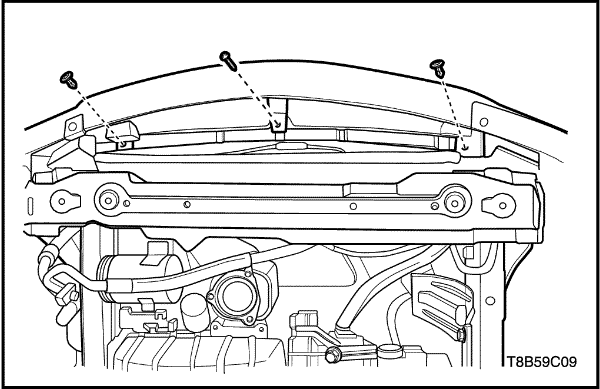
- Remove the screws on the top of the fascia.
- Remove the front bumper fascia.
Installation Procedure
Notice : Dissimilar metals in direct contact with each other may corrode rapidly. Make sure to use the correct fasteners to prevent premature corrosion.
- Install the bumper fascia.
- Install the screws on the top of the fascia.
- Install the nuts behind the fascia.
Tighten
Tighten the front bumper impact beam nuts to 27 N•m (20 Ib-ft).
- Install the screws underneath the fascia.
Tighten
Tighten the frontwheelwell screws to 1.5 N•m(13 lb-in).
- Install the headlamps, the turn signal lamp, the side turn signal lamps, and the front fog lamps. Refer to Section 9B, Lighting Systems.
- Install the front wheel well splash shields with the screws, the bolts, and the nuts.
- Install the front wheels. Refer to Section 2E, Tires and Wheels.
Tighten
Tighten the splash shield screws to 1.5 N•m(13 lb-in).
Tighten the splash shield bolts to 1.5 N•m (13 lb-in).
Tighten the splash shield nuts to 1.5 N•m (13 lb-in).
- Connect the negative battery cable.
Front Bumper Impact Beam
Removal Procedure
- Remove the front bumper fascia. Refer to "Front Bumper Fascia"
in this section.
- Remove the front bumper impact beam.
Installation Procedure
- Install the front bumper impact beam.
- Install the front bumper fascia. Refer to "Front Bumper Fascia"
in this section.
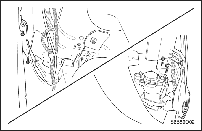
Front Bumper Fascia - Hatchback -
Removal Procedure
- Raise and suitably support the vehicle.
- Remove the front wheel. Refer to Section 2E, Tires and Wheels.
- Remove the fender liners. Refer to Section 9R, Body Front End.
- Remove the headlamps. Refer to Section 9B, Lighting Systems.
- Remove the radiator grille. Refer to Section 9R, Body Front End.
- Remove the clips along the top of the bumper fascia.
- Remove the clips and screw along the bottom of the bumper fascia.
- Remove the bolts on the inside of the bumper fascia.
- Remove the front bumper fascia.
Installation Procedure
- Install the front bumper fascia.
- Install the bolts on the inside of the bumper fascia.
Tighten
Tighten the front bumper fascia bolts to 1.5 N•m (13 lb-in).
- Install the clips and screw along the bottom of the bumper fascia.
Tighten
Tighten the front bumper fascia screw to 1.5 N•m (13 lb-in).
- Install the clips along the top of the bumper fascia.
- Install the radiator grille. Refer to Section 9R, Body Front End.
- Install the headlamps. Refer to Section 9B, Lighting Systems.
- Install the fender liners. Refer to Section 9R, Body Front End.
- Install the front wheel. Refer to Section 2E, Tires and Wheels.
- Lower the vehicle.
Front Bumper Impact Beam - Hatchback -
Removal Procedure
- Remove the front bumper fascia. Refer to "Front Bumper Fascia (Hatchback)"
in this section.
- Remove the front bumper impact beam nuts.
- Remove the front bumper impact beam.
Installation Procedure
- Install the front bumper impact beam.
- Install the front bumper impact beam nuts.
Tighten
Tighten the front bumper impact beam nuts to 24 N•m (18 lb-ft).
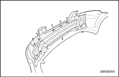
Rear Bumper Fascia
Removal Procedure
- Remove the rear wheels. Refer to Section 2E, Tires and Wheels.
- Remove the screws and the mud guards.
- Remove the screws and the splash shields.
- Remove the screws behind the fascia.
- Remove the nuts behind the rear bumper energy absorber.
- Remove the luggage compartment rear quarter trim panels. Refer to Section 9G, Interior Trim.
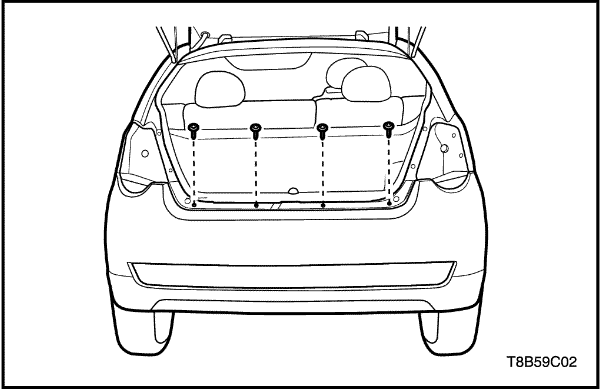
- Remove the bolts and the nuts in the luggage compartment.
- Remove the rear upper fascia screws.
- Remove the fascia.
Installation Procedure
Notice : Dissimilar metals in direct contact with each other may corrode rapidly. Make sure to use the correct fasteners to prevent premature corrosion.
- Install the fascia with the rear upper fascia screws.
Tighten
Tighten the rear upper fascia screws to 1.5 N•m (13 lb-in).
- Install the bolts and the nuts in the luggage compartment.
Tighten
Tighten the luggage compartment fascia bolts to 4 N•m (35 lb-in).
- Install the luggage compartment rear quarter trim panels.Refer to Section 9G, Interior Trim.
- Install the nuts behind the rear bumper energy absorber.
Tighten
Tighten the rear bumper energy absorber nuts to 24 N•m (18 lb-ft).
- Install the screws behind the fascia.
Tighten
Tighten the behind fascia screws to 1.5 N•m (13 lb-in).
- Install the splash shields with the screws.
Tighten
Tighten the splash shield screws to 1.5 N•m (13 lb-in).
- Install the mud guards with the screws.
Tighten
Tighten the mud guard screws to 1.5 N•m (13 lb-in).
- Install the rear wheels. Refer to Section 2E, Tires and Wheels.
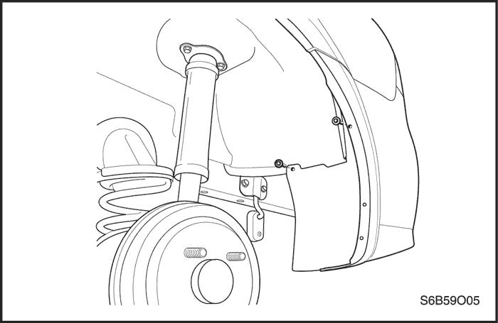
Rear Bumper Fascia - Hatchback -
Removal Procedure
- Raise and suitably support the vehicle.
- Remove the rear wheel. Refer to Section 2E, Tires and Wheels.
- Remove the tail lamp. Refer to Section 9B, Lighting Systems.
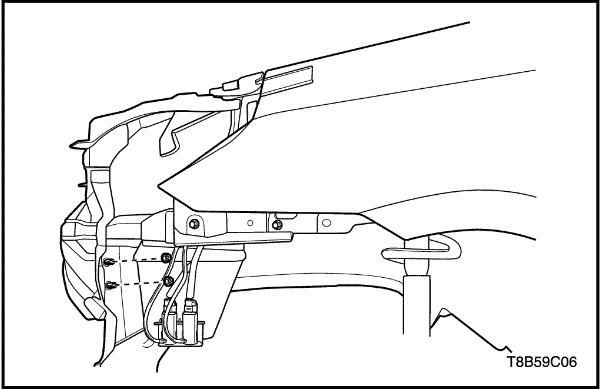
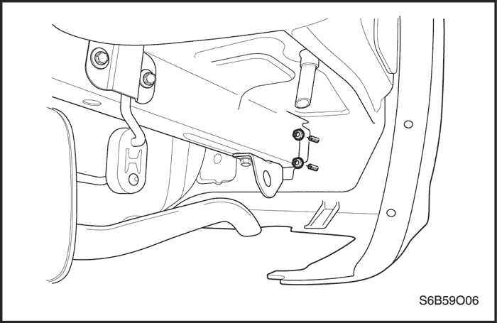
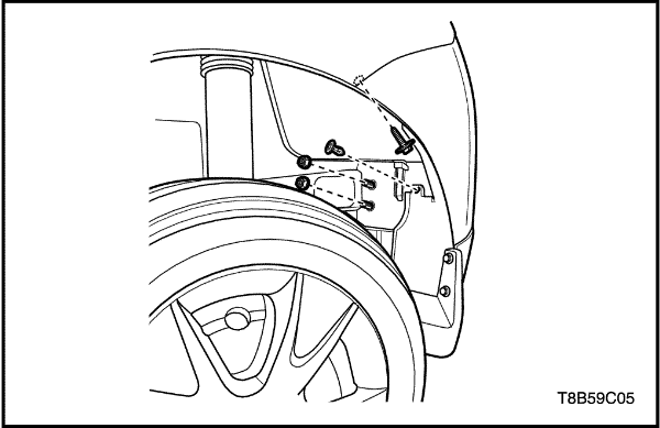
- Remove the rear bumper fascia nuts, bolt and clip along the rear wheel house.
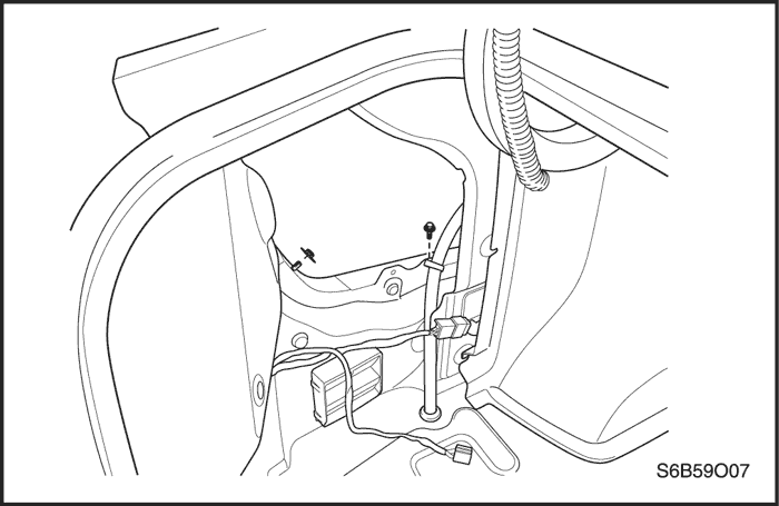
- Remove the trunk end trim clips.
- Remove the trunk end trim.
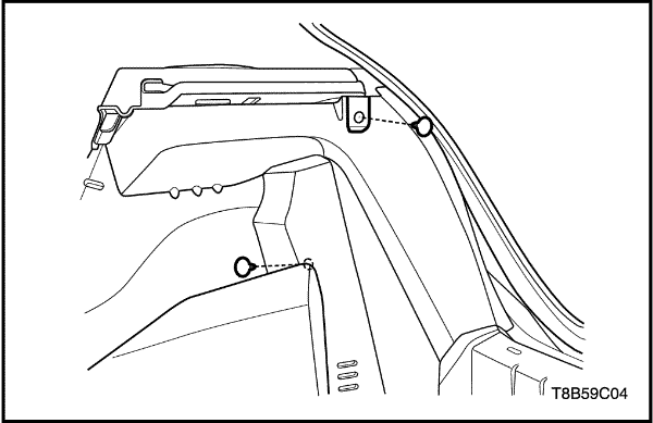
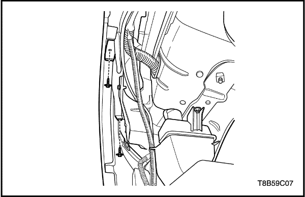
- Remove the rear side panel trim clip and screw.
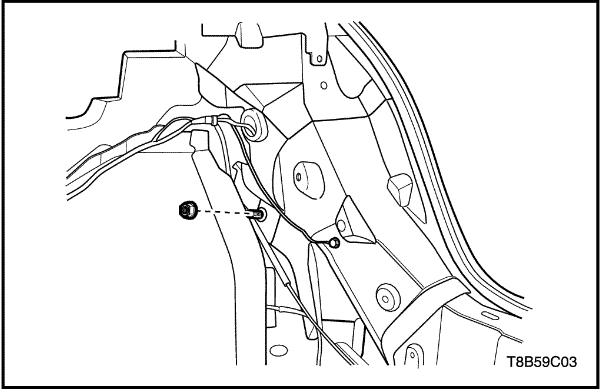
- Remove the rear bumper fascia-to-lower back panel nut through a gap between rear side panel trim and lower back panel.
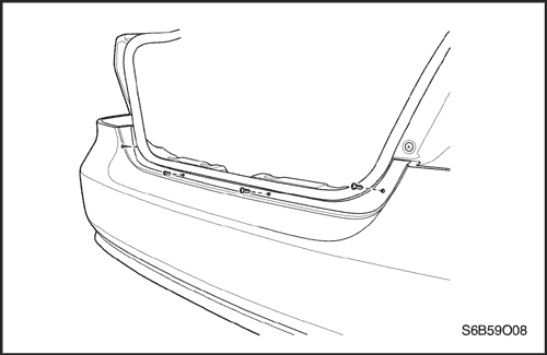
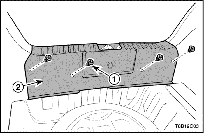
- Remove the rear bumper fascia screws.
- Remove the rear bumper fascia.
Installation Procedure
- Install the rear bumper fascia.
- Install the rear bumper fascia screws.
Tighten
Tighten the rear bumper fascia screws to 1.5 N•m (13 lb-in).
- Install the rear bumper fascia-to-lower back panel nut through a gap between rear side panel trim and lower back panel.
Tighten
Tighten the rear bumper fascia-to-lower back panel nut to 4 N•m(35 lb-in).
- Install the rear side panel trim clip and screw.
Tighten
Tighten the rear side panel trim screw to 1.5 N•m (13 lb-in).
- Install the trunk end trim.
- Install the trunk end trim clips.
- Install the rear bumper fascia nuts, bolt and clip along the rear wheel house.
Tighten
- Tighten the rear bumper fascia nuts to 25 N•m (18 lb-ft).
- Tighten the rear bumper fascia bolt to 1.5 N•m(13 lb-in).
- Install the tail lamp. Refer to Section 9B, Lighting Systems.
- Install the rear wheel. Refer to Section 2E, Tires and Wheels.
- Lower the vehicle.
GENERAL DESCRIPTION
AND SYSTEM OPERATION
Bumpers
The bumper systems are designed to sustain a collision into a fixed barrier at either 8km/h (5 mph) or 4km/h (2.5 mph) without damage.
After absorbing the energy of a collision, these bumper systems restore themselves to their original position. Both the front and the rear bumpers feature an internal foam energy absorber and a polymer fascia cover. The rear bumper fascia must be removed before access can be gained to the energy absorber and the bumper. The front bumper assembly can be removed as a whole unit or the fascia cover can be removed separately.


