Aveo |
||||||||
|
||||||||
|
Application
|
N•m
|
Lb-Ft
|
Lb-In
|
|
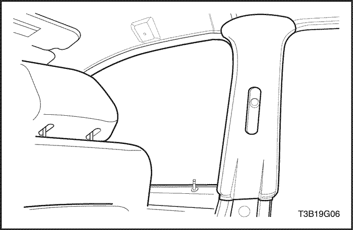
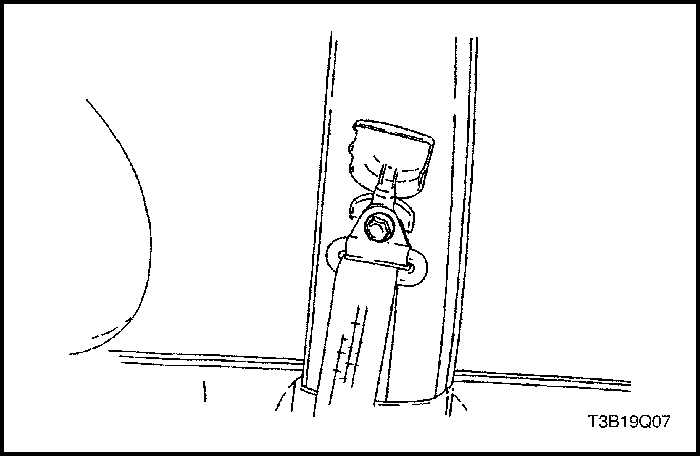
B-Pillar Seat Belt Bolts
|
38
|
28
|
-
|
|
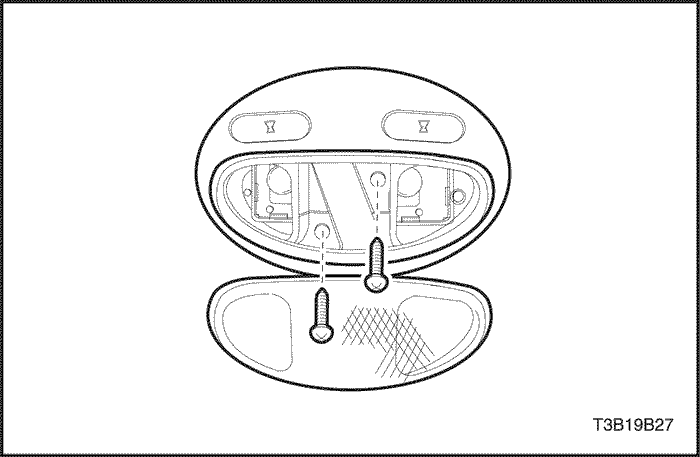
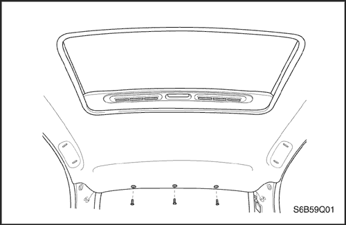
Interior Courtesy Lamp/Power Sunroof Control Switch Screws
|
2.5
|
-
|
22
|
|
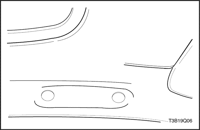
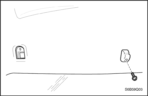
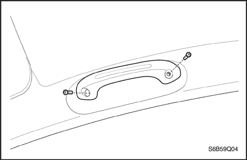
Passenger Assist Handle Screws
|
3.5
|
-
|
31
|
|
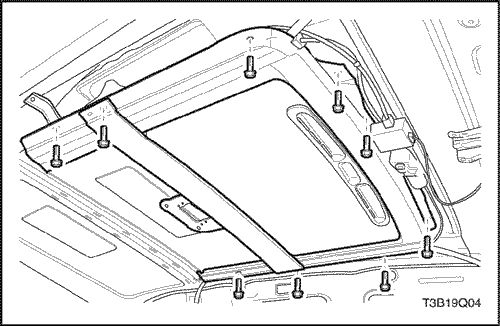
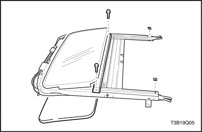
Sunroof Glass Screws
|
7
|
-
|
62
|
|
Sunroof Housing Bolts
|
7
|
-
|
62
|
|
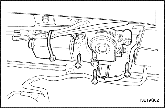
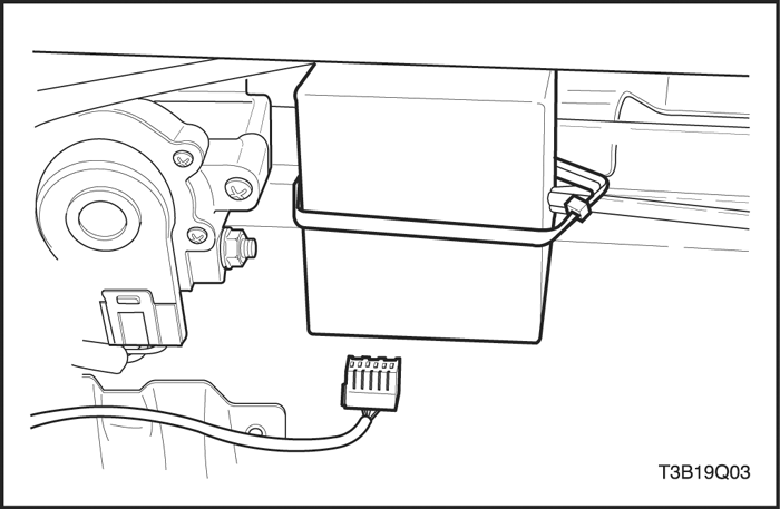
Sunroof Motor Screws
|
5
|
-
|
44
|
|
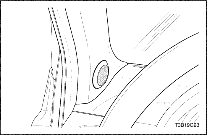
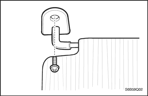
Sun Visor Screws
|
1.5
|
-
|
13
|
|
Sun Visor Support Screw
|
1.5
|
-
|
13
|
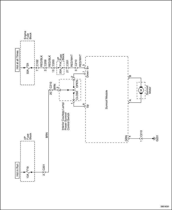
| Step | Action | Value(s) | Yes | No |
| 1 |
Check fuses F19 and Ef1.
Is either fuse blown?
|
-
|
Go to Step 2
|
Go to Step 3
|
| 2 |
Is the repair complete?
|
-
|
System OK
|
-
|
| 3 |
Are both voltages equal to the specified value?
|
11 - 14 v
|
Go to Step 5
|
Go to Step 4
|
| 4 |
Repair the power supply to the fuse which did not indicate battery voltage with the ignition on.
Is the repair complete?
|
-
|
System OK
|
-
|
| 5 |
Is the voltage equal to the specified value?
|
11-14 v
|
Go to Step 7
|
Go to Step 6
|
| 6 |
Repair the open circuit between fuse F19 and the interior courtesy lamp/power sunroof control switch connector.
Is the repair complete?
|
-
|
System OK
|
-
|
| 7 |
Do both voltages equal the specified value?
|
11 - 14 v
|
Go to Step 9
|
Go to Step 8
|
| 8 |
Replace the interior courtesy lamp/power sunroof control switch.
Is the repair complete?
|
-
|
System OK
|
-
|
| 9 |
Are the voltages equal to the specified value?
|
11-14 v
|
Go to Step 11
|
Go to Step 10
|
| 10 |
Repair the open circuit between the interior courtesy lamp/power sunroof control switch and the sunroof module connector.
Is the repair complete?
|
-
|
System OK
|
-
|
| 11 |
Does the motor operate?
|
-
|
Go to Step 12
|
Go to Step 13
|
| 12 |
Repair the jammed sunroof mechanism.
Is the repair complete?
|
-
|
System OK
|
-
|
| 13 |
Does the voltmeter indicate the specified voltage when the switch is in either the OPEN or the CLOSE position (one of the switch positions should show reverse polarity)?
|
11-14v
|
Go to Step 15
|
Go to Step 14
|
| 14 |
Replace the sunroof module.
Is the repair complete?
|
-
|
System OK
|
-
|
| 15 |
Replace the sunroof motor.
Does the sunroof operate with the new motor?
|
-
|
System OK
|
Go to Step 14
|
| © Copyright Chevrolet Europe. All rights reserved |


