Drivetrain and Front Suspension Frame Replacement — with EN-49802
Special Tools
EN-49802 Cradle Supporter
For equivalent regional tools refer to Special Tools
Removal Procedure
- Raise and support the vehicle. Refer to Vehicle Lifting and Jacking Caution .
- Remove the front wheel and wheel assemblies. Refer to Tire and Wheel Removal and Installation .
- Remove both front compartment splash shields. Refer to Front Compartment Splash Shield Replacement .
- Remove the front under cover.
- Remove both of the front wheel house linings.
- Remove the front bumper fascia. Refer to Front Bumper Fascia Replacement .
- Remove the lower wind guard.
- Secure the cooling module to the left and right of the upper body structure with a wire.
- Separate both of the control arm ball joints from the steering knuckles. Refer to Lower Control Arm Replacement .
- Remove both of the upper stabiliser shaft link nuts and separate the left and right stabiliser shaft link from the strut. Refer to Stabilizer Shaft Link Replacement .
- Remove the exhaust pipe. Refer to Exhaust Pipe Replacement .
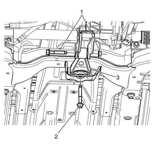
- Remove the torque strut to transmission mounting bracket bolt and nut (1) and the torque strut to frame bolt (2).
- Remove the torque strut (3) from the frame.
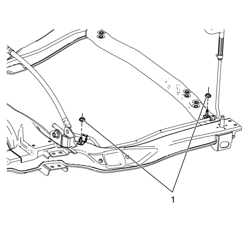
- Remove the power steering pipe/hose retaining nuts (1) and separate the pipe from the frame. Refer to Power Steering Gear Outlet Pipe/Hose Replacement .
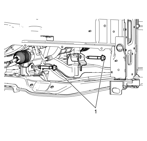
- Remove the steering gear assembly to the frame retaining bolts (1) and separate the steering gear assembly from the frame. Refer to Steering Gear Replacement .
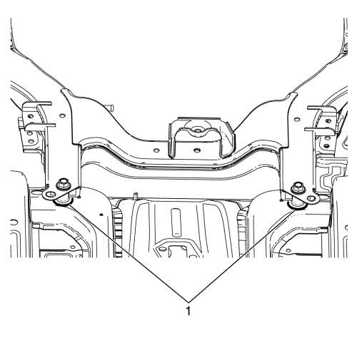
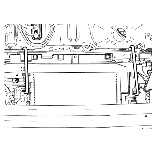
- Mark the frame to body positions (1) with a paint pen or permanent marker.
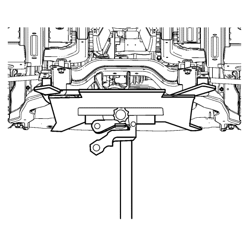
- Install the EN-49802 cradle supporter to a hydraulic jack stand and support the frame.
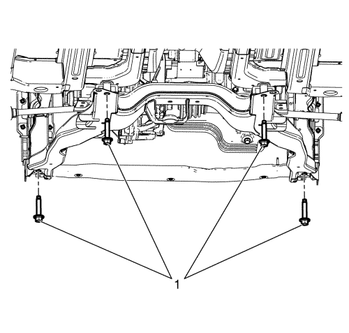
- Remove the frame to body bolts (1).
- Slowly lower the jack stand and remove the frame from the vehicle.
- Remove the following components if replacing the frame:
| 20.3. | Remove the radiator brackets from the frame. |
| 20.4. | Remove the front lower impact bar. |
Installation Procedure
- Install the following components to the frame if removed:
| 1.1. | Install the front lower impact bar to the frame. |
| 1.2. | Install the radiator brackets to the frame. |
- With the frame on the EN-49802 cradle supporter and hydraulic jack stand, raise the frame to the vehicle.
- Hand start all the frame to body retaining bolts while aligning the frame to the paint marks (1).
Caution: Refer to Fastener Caution in the Preface section.
- Tighten the frame to body retaining bolts (1) to 170 N·m (125 lb ft).
- Lower the jack stand and remove the EN-49802 cradle supporter.
- Install the steering gear assembly to the frame retaining bolts. Refer to Steering Gear Replacement .
- Install the power steering pipe to the frame and tighten the pipe retaining nuts. Refer to Power Steering Gear Outlet Pipe/Hose Replacement
- Install the torque strut (3) from the frame.
- Install the torque strut to the frame bolt (2) and tighten to 100 N·m (74 lb ft).
- Install the torque strut to the transmission mounting bracket bolt and nut (1) and tighten to 80 N·m (59 lb ft).
- Install the exhaust pipe. Refer to Exhaust Pipe Replacement .
- Connect both of the stabiliser shaft links to the struts and tighten the upper stabiliser shaft link nuts. Refer to Stabilizer Shaft Link Replacement .
- Install both of the control arm ball joints to the steering knuckles. Refer to Lower Control Arm Replacement .
- Remove the wires which secure the cooling module to the upper body structure.
- Install the lower wind guard.
- Install the front bumper fascia. Refer to Front Bumper Fascia Replacement .
- Install both of the front wheel house linings.
- Install the front under cover.
- Install both of the front compartment splash shields. Refer to Front Compartment Splash Shield Replacement .
- Install the front wheel and wheel assemblies. Refer to Tire and Wheel Removal and Installation .
- Lower the vehicle.
- Road test the vehicle in order to test for the following conditions:
| • | Abnormal powertrain noise or vibration at tick over--Inspect the engine and transmission mounts for proper alignment and torque. |
| © Copyright Chevrolet. All rights reserved |


