Warning: Refer to Battery Disconnect Warning in the Preface section.
- Open the bonnet.
- Depressurise the fuel system. Refer to Fuel Pressure Relief .
- Disconnect the battery negative cable. Refer to Battery Negative Cable Disconnection and Connection .
- Recover the air conditioning (A/C) refrigerant. Refer to Refrigerant Recovery and Recharging .
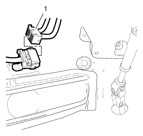
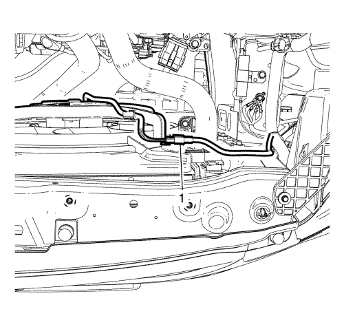
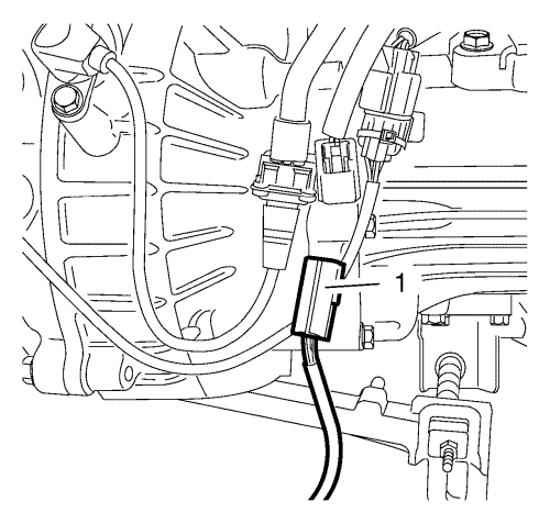
- Disconnect the engine wiring harness (1) in the leg room.
- Remove the bonnet. Refer to Bonnet Replacement .
- Remove the plenum lower panel. Refer to Plenum Lower Panel Replacement .
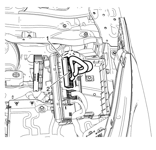
- Disconnect intake air temperature sensor connector (1).
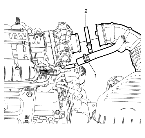
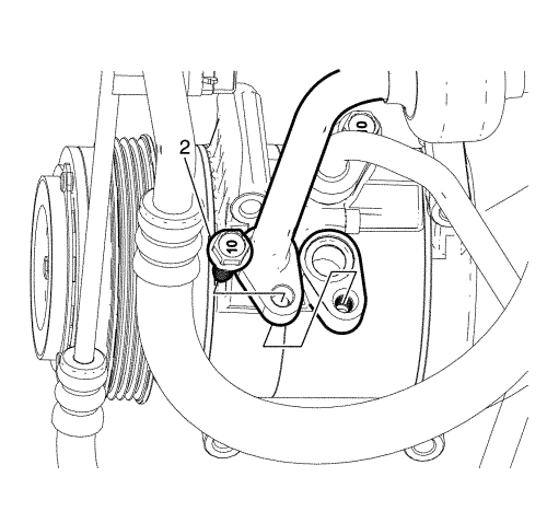
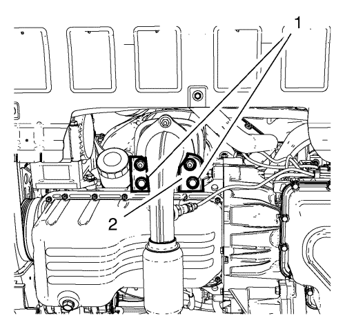
- Remove the clamps (1, 2).
- Twist and pull the hoses to remove throttle body assembly.
- Disconnect the accelerator cable, if equipped.
- Remove the battery. Refer to Battery Replacement .
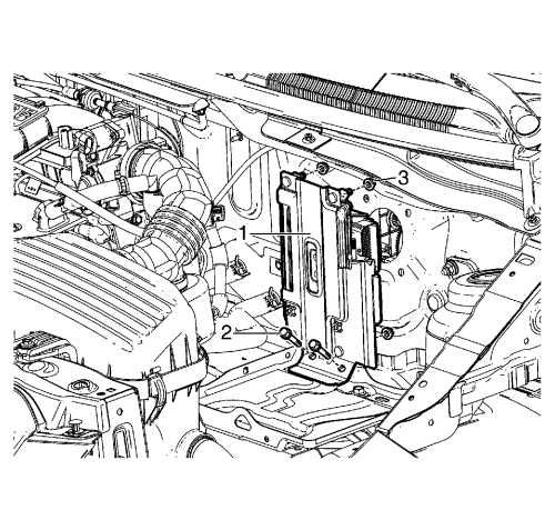
- Remove the engine control module (ECM) bracket to battery tray retaining bolts (2).
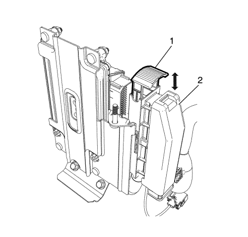
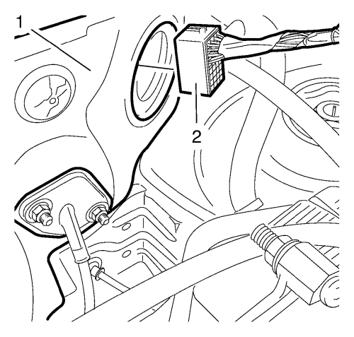
- Pull the engine control module (ECM) electrical connector lever (1) and disconnect the engine control module (ECM) electrical connector (2).
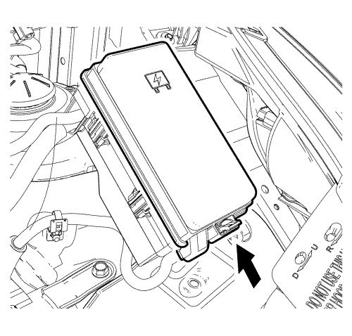
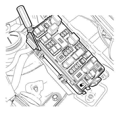
- Remove the under hood body electrical centre (BEC) cover.
Unlock latch (arrow).
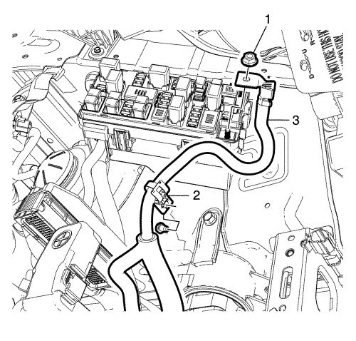
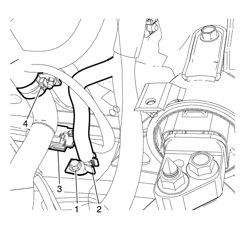
- Remove the positive cable to body electrical centre (BEC) retaining nut (1).
- Pull back the positive cable (3) to separate the positive cable retainer (2) from body.
- Raise the upper plate with suitable tool.
- Remove the under hood BEC upper plate to lower plate retaining bolts (2).
- Disconnect the wiring harness plug (1) from the front compartment fuse block.
- Remove the ground bolt (1) and put the wiring harness (2) aside.
- Disconnect the wheel speed sensor connector (3).
- Move the wiring harness retainer (4) aside with suitable tool.
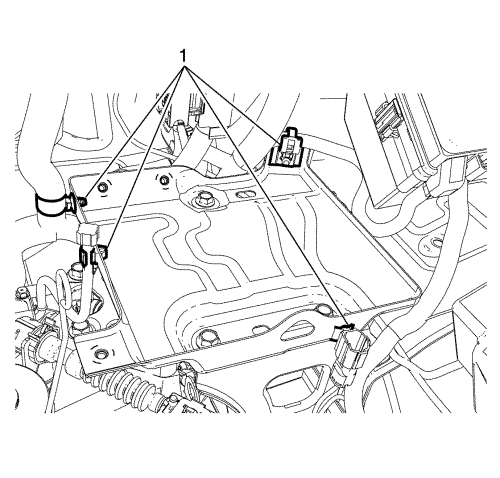
- Remove the retainers (1) from the battery tray with a suitable tool.
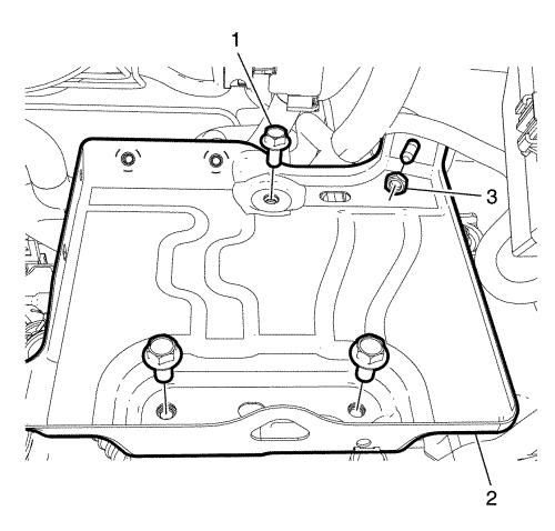
- Remove the bolts (1) and nut (3).
- Remove the battery tray (2)
- Remove the engine wiring harness (2) from the bulkhead (1).
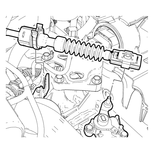
- Disconnect the transmission range selector lever cable terminal from the transmission lever pin. Refer to Manual Gearbox Gear Lever and Selector Lever Cable Replacement .
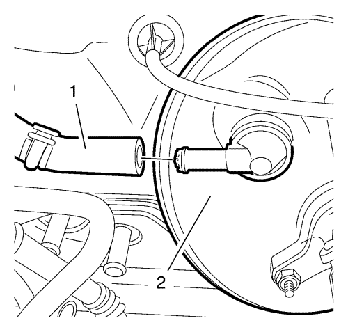
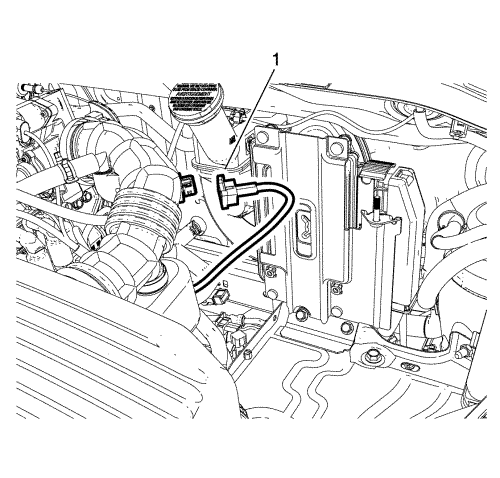
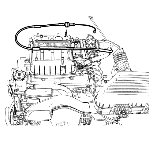
- Disconnect the vacuum hose (1) from the power vacuum brake booster (2).
- Remove the surge tank clip.
- Raise and support the vehicle. Refer to Lifting and Jacking the Vehicle .
- Remove the front wheels. Refer to Tyre and Wheel Removal and Installation .
- Remove the front bumper fascia. Refer to Front Bumper Fascia Replacement .
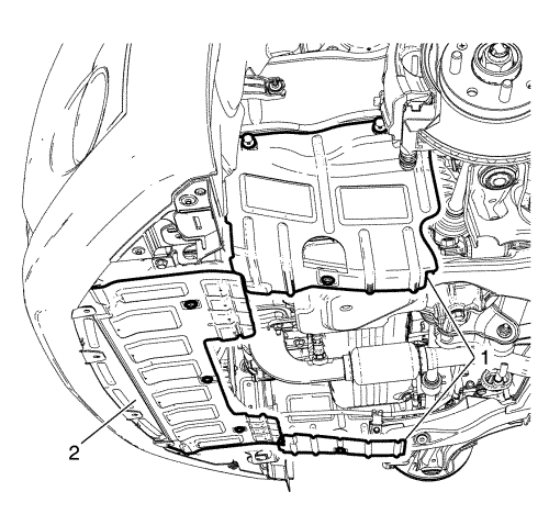
- Remove the 3 cover bolts.
- Remove the cover (2).
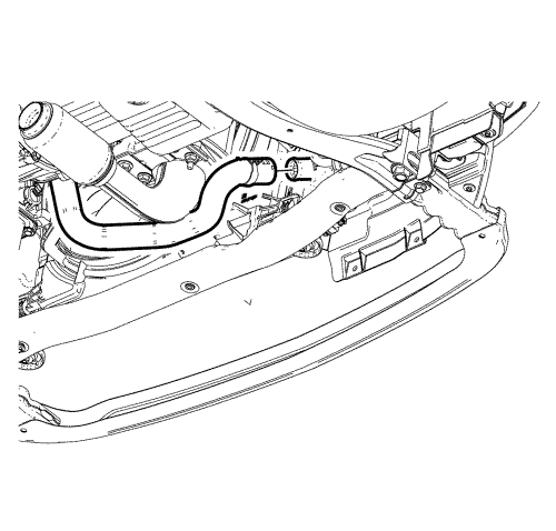
- Place a suitable container beneath the radiator and engine.
- Drain the cooling system by disconnecting lower coolant hose as shown.
- Lower the vehicle.
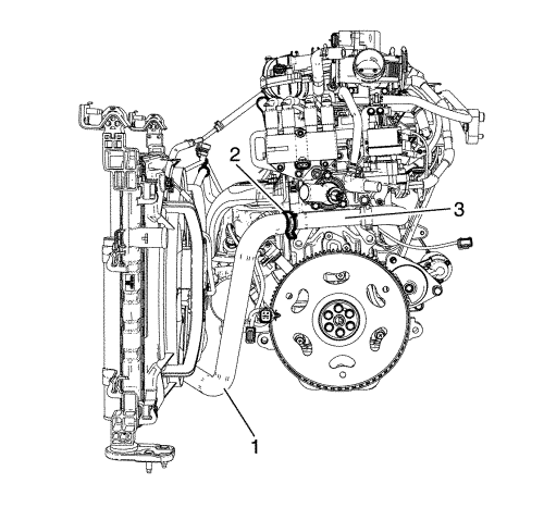
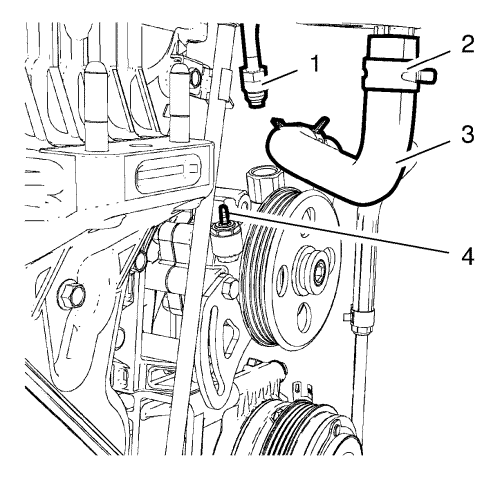
- Loosen the radiator outlet hose clamp (2).
- Remove the radiator outlet hose (1) from the water pump outlet pipe (3).
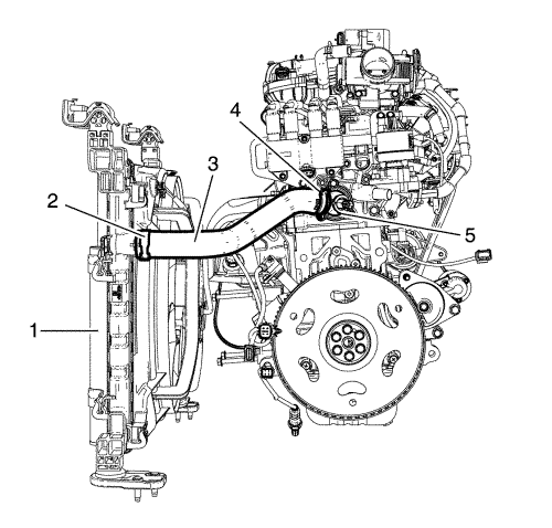
- Loosen the radiator inlet hose clamp (4).
- Loosen the radiator inlet hose (3) from the engine coolant thermostat housing (5).
- Disconnect the fan module connector (1).
- Disconnect the ambient air temperature sensor connector (2), if equipped.
- Disconnect the coolant hose (1) from the CRFM.
- Disconnect the engine coolant temperature sensor (radiator) wiring harness.
- Unclip the 6 front compartment panel clips.
- Remove the 2 front compartment panels.
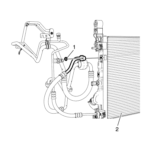
- Remove the A/C compressor and condenser hose nut (1) from A/C condenser (2).
- Remove the A/C compressor and condenser hose bolt (1) from A/C compressor (2).
- Remove the A/C compressor and condenser hose.
- Remove the A/C evaporator hose assembly bolt to A/C compressor (2).
- Disconnect the A/C evaporator hose assembly from the A/C compressor.
- Remove A/C compressor and condenser hose nut (1) from A/C condenser.
Note: The A/C sealing O-rings are a single use component and will not reseal. Install NEW A/C sealing O-rings whenever the A/C suction/discharge line pad is removed from the A/C compressor.
- Remove and DISCARD the A/C suction/discharge pipe sealing O-rings.
Note: Plug or cap the A/C suction/discharge pipe ends and the compressor ports immediately to prevent contamination and absorption of moisture from the atmosphere.
- Plug or cap the A/C suction/discharge pipe ends, the compressor and the condenser ports.
- Raise the vehicle.
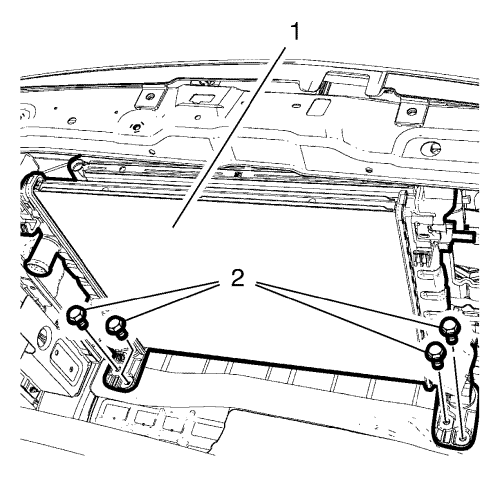
- Loosen the 4 radiator support mounting bolts (2).
| | Note: 2nd person required. |
| 58.1. | Remove the 4 radiator support mounting bolts (2), |
| 58.2. | Remove engine cooling fan shroud, condenser and radiator (1) downward. |
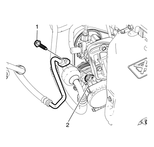
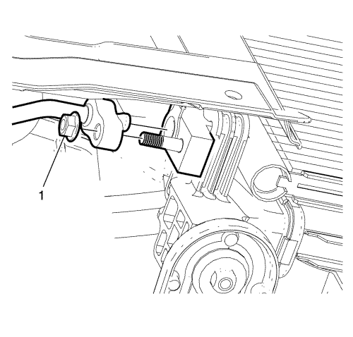
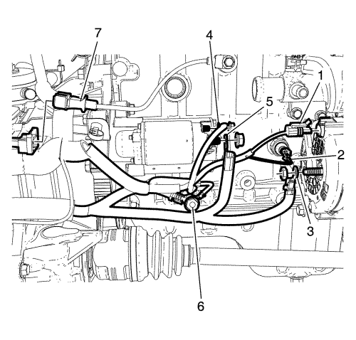
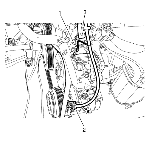
- Remove the power steering pipe bolt (1).
- Remove the power steering pipe (3) from the alternator bracket (2).
- Lower the vehicle.
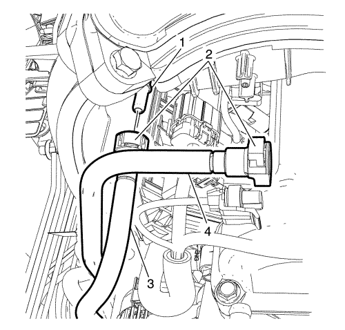
- Remove the power steering inlet hose (1) from the fluid pressure switch connector (4).
Note: Plug or cap the power inlet hose and the fluid pressure switch connector to prevent hydraulic oil leaks and/or contamination.
- Plug or cap the power steering inlet hose and the fluid pressure switch connector.
- Pinch off the power steering fluid reservoir outlet hose (3).
- Loosen the power steering fluid reservoir outlet hose clamp (2).
- Remove the power steering fluid reservoir outlet hose (3) from the power steering fluid reservoir.
Note: Plug or cap the power steering fluid reservoir outlet hose to prevent hydraulic oil leaks and/or contamination.
- Plug or cap the power steering fluid reservoir outlet hose.
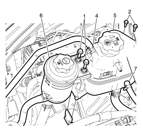
- Remove power steering fluid reservoir bolts (1) and unclip the power steering fluid reservoir and hang it aside.
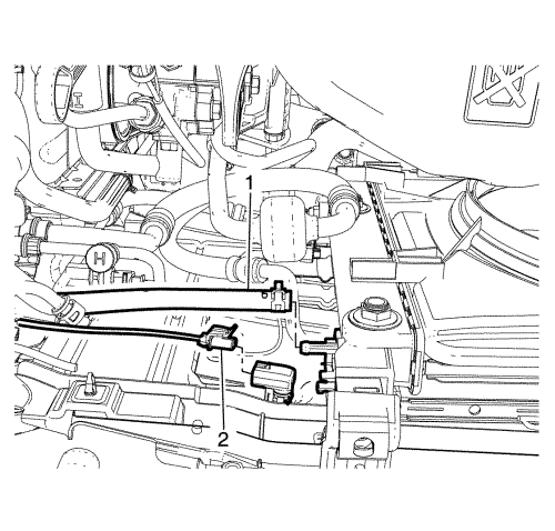
- Disconnect the coolant hoses (3, 4, 7) from the coolant surge tank.
- Remove the coolant surge tank to body retaining bolts (2).
- Remove the coolant surge tank (5).
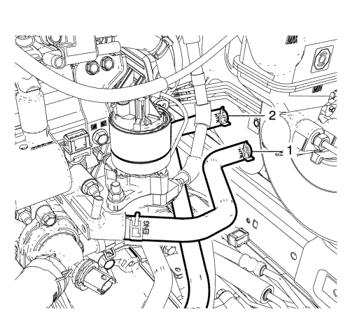
- Disconnect the heater inlet hose (1) and outlet hose (2) from the heater pipe.
Warning: Refer to Fuel and Evaporative Emission Pipe Warning in the Preface section.
Warning: Always wear safety goggles when working with fuel in order to protect the eyes from fuel splash.
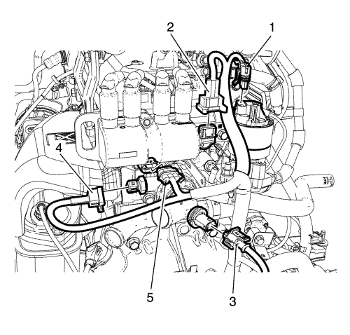
- Disconnect the evaporative emission (EVAP) purge line (4) from the purge solenoid.
Note: When removal is complete plug hose openings with a clean lint free cloth to prevent foreign matter entry.
- Plug or cap the (EVAP) purge line (4) and the purge solenoid ends.
- Disconnect the fuel feed hose (3) from the fuel feed pipe (1).
Caution: Cap the fittings and plug the holes when servicing the fuel system in order to prevent dirt and other contaminants from entering the open pipes and passages.
- Plug or cap the fuel feed pipe (1) and fuel feed hose (3) ends.
- Remove the exhaust heat shield. Refer to Exhaust Manifold Heat Shield Replacement .
- Remove the 3 catalytic converter nuts .
- Cut the cable strap, if equipped.
- Disconnect the heated oxygen sensor 2 wiring harness plugs (1).
- Raise the vehicle.
- Remove 2 catalytic converter bracket bolts (1) from the catalytic converter bracket (2).
Note: 2nd person required.
- Remove the exhaust pipe with included catalytic converter. Refer to Exhaust Pipe Replacement .
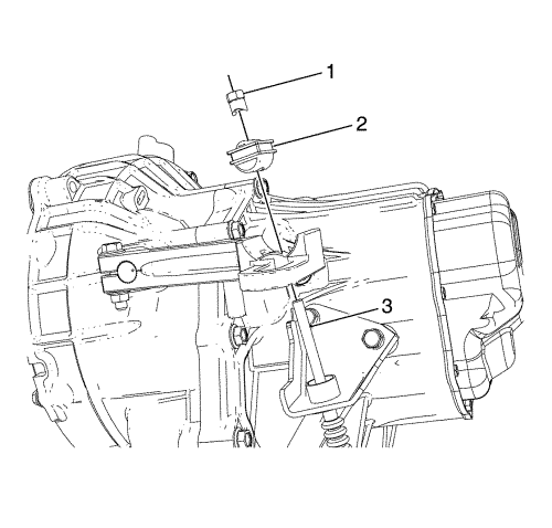
- Remove the clutch cable (3) from the clutch cable bracket hole.
- Remove the clutch release bumper assembly (2) from the clutch cable (3).
- Remove the clutch cable adjusting nut (1).
- Remove the 2 steering linkage outer track rods from the steering knuckle. Refer to Steering Linkage Outer Track rod Replacement .
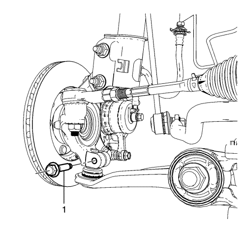
- Remove the lower control arm ball joint to steering knuckle retaining bolt (1) and separate the ball joint from the steering knuckle.
- Remove the 2 front wheel drive shafts from the transmission. Refer to Front Wheel Drive Shaft Replacement .
- Remove the transmission rear mount bracket. Refer to Transmission Rear Mount Bracket Replacement .
- Remove the transmission rear mount. Refer to Transmission Rear Mount Replacement .
- Lower the vehicle.
- Remove the manifold absolute pressure (MAP) sensor. Refer to Manifold Absolute Pressure Sensor Replacement .
- Remove the evaporative emission canister purge solenoid valve. Refer to Evaporative Emission Canister Purge Solenoid Valve Replacement .
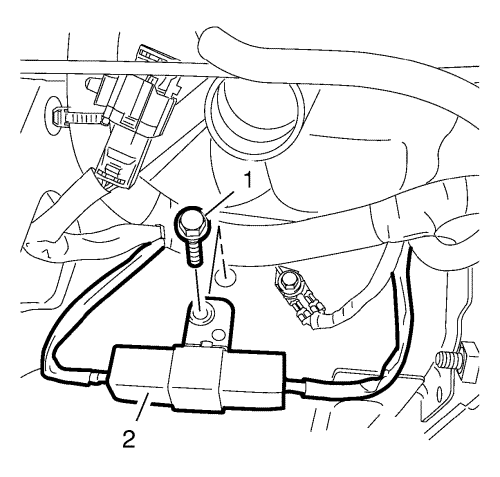
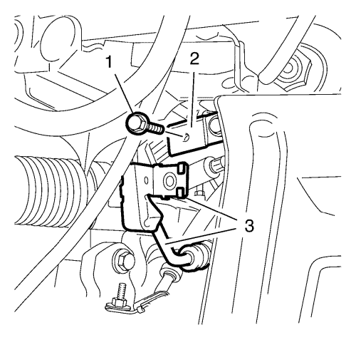
- Remove the series resistor bolt (1).
- Put the series resistor aside (2).
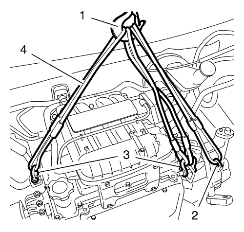
- Install a suitable engine lifting device (1).
- Install a suitable cable (4) to the engine lifting device (1).
- Install a suitable cable (4) to the 2 engine lift brackets (3).
- Install a suitable cable (4) to the transmission lift bracket (2).
- Extend the engine lifting device (1) until the steel cable (4) is slightly tensioned.
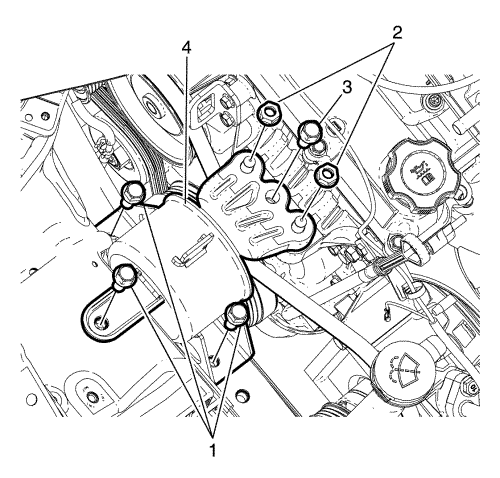
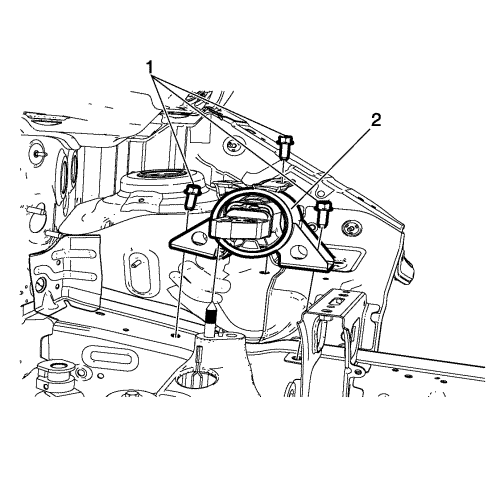
- Remove the 2 engine mount nuts (2).
- Remove the engine mount bolt (3).
- Remove the 3 engine mount to body retaining bolts (1).
- Remove the engine mount (4).
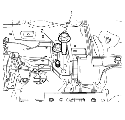
- Remove the left transmission mount bolt (1) from the transmission mount bracket.
- Remove the left transmission mount nut (2) from the transmission mount bracket.
- Remove the left transmission mount to body bolts (1).
- Remove the transmission mount (2) from the vehicle.
- Lower the engine transmission unit.
Note: 2nd person required.
- Turn the engine transmission unit (1) under the transmission mount support (2).
Caution: To ensure that damage does not occur, gently remove the engine from the front compartment, with the aid of assistants, two recommended. Special attention must be paid to the windscreen area as the engine passes. The engine must be kept away from the windscreen as much as possible. Failure to follow this instruction could lead to windscreen damage and require windscreen replacement.
Note: 3rd person required.
- Carefully remove the engine transmission unit (1) upwards.
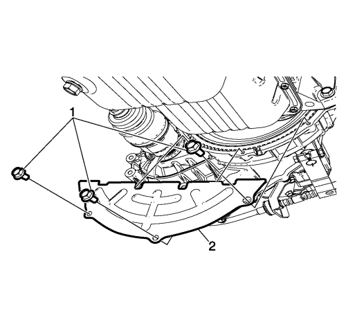
- Remove the clutch housing lower plate bolt (1) and clutch housing lower plate (2).
- Put the engine transmission unit down on a wooden pallet.
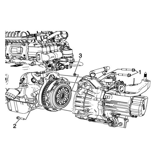
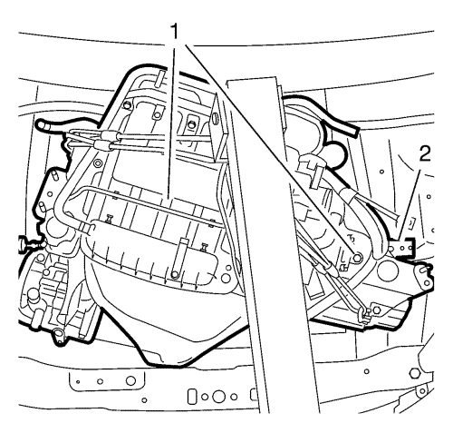
- Remove the transmission upper bolts (1).
Note: 2nd person required.
- Remove the transmission
| 116.1. | Remove the transmission lower bolt (2) |
| 116.2. | Remove the transmission lower nut (3) |
| 116.3. | Separate the transmission from the engine. |
- Remove the clutch pressure and driven plate. Refer to Clutch Pressure and Driven Plate Replacement .
- Install the engine to a suitable engine stand.
- Remove the engine wiring harness ground to cylinder block retaining bolt (6).
- Remove the battery positive cable to alternator retaining nut.
- Disconnect the battery positive cable (3) from the alternator.
- Remove the starter and alternator wiring harness .
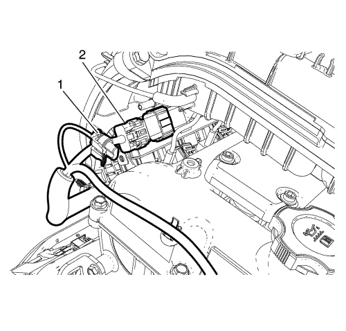
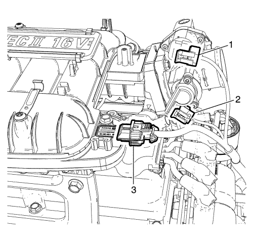
- Disconnect the alternator harness connector (1), oil pressure switch connector (2) and knock sensor connector (7).
- Disconnect the power steering connector (1), and A/C compressor electrical connector (2).
- Disconnect the canister purge solenoid connector (1) and the injector harness electrical connector (2).
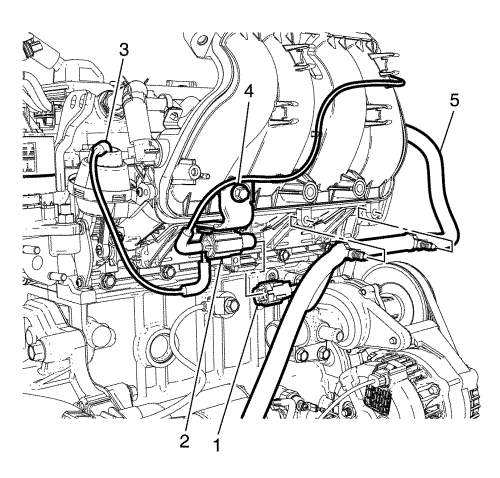
- Disconnect the intake manifold runner control valve connector (1) and detach the wiring harness (5) from intake manifold.
- Disconnect the exhaust gas recirculation (EGR) connector (1), camshaft position sensor connector (2), thermostat heater connector (3), engine coolant temperature sensor connector (4), and DIS connector (5).
- Disconnect the idle air control valve (IACV) connector (1) and throttle position sensor (TPS) connector (2).
- Remove the engine wiring harness from the engine.
- Remove the generator. Refer to Generator Replacement .
- Remove the power steering pump. Refer to Power Steering Pump Replacement .
- Remove the A/C compressor. Refer to Air Conditioning Compressor Replacement .
- Transfer parts as needed.
- Remove the engine from the engine stand.
- Transfer the steel cable to engine lift brackets.
- Install the NEW engine to a suitable engine stand.
- Install the A/C compressor. Refer to Air Conditioning Compressor Replacement .
- Install the power steering pump. Refer to Power Steering Pump Replacement .
- Install the generator. Refer to Generator Replacement .
- Position the engine wiring harness to the engine.
- Connect the idle air control valve (IACV) connector (1) and throttle position sensor (TPS) connector (2).
- Connect the exhaust gas recirculation (EGR) connector (1), camshaft position sensor connector (2), thermostat heater connector (3), engine coolant temperature sensor connector (4), and DIS connector (5).
- Connect the intake manifold runner control valve connector (1) and attach the wiring harness (5) to the intake manifold.
- Connect the canister purge solenoid connector (1) and the injector harness electrical connector (2).
- Attach the engine wiring harness clip (3) to the bracket.
- Connect the power steering connector (1), and A/C compressor electrical connector.
- Connect the alternator harness connector (1), oil pressure switch connector (2), and knock sensor connector (7).
Caution: Refer to Fastener Caution in the Preface section.
- Install the engine wiring harness ground to cylinder block and tighten the bolt (6) to 50 N·m (37 lb ft).
Note: 2nd person required.
- Remove the engine from the engine stand, using the engine lifting device.
- Put the engine down on a wooden pallet.
- Install the clutch pressure and driven plate. Refer to Clutch Pressure and Driven Plate Replacement .
Note: 2nd person required.
- Install the transmission to the engine.
| 18.1. | Install the transmission lower nut (3) and tighten to 61 N·m (45 lb ft). |
| 18.2. | Install the transmission lower bolt (2) and tighten to 61 N·m (45 lb ft) |
- Install the transmission upper bolts (1) and tighten to 61 N·m (45 lb ft)
- Install a suitable cable to the transmission lift bracket.
- Raise the engine transmission unit using the engine lifting device.
- Install the clutch housing lower plate bolt (1) and clutch housing lower plate (2) and tighten to 10 N·m (89 lb in).
Caution: To ensure that damage does not occur, gently remove the engine from the front compartment, with the aid of assistants, two recommended. Special attention must be paid to the windscreen area as the engine passes. The engine must be kept away from the windscreen as much as possible. Failure to follow this instruction could lead to windscreen damage and require windscreen replacement.
Note: 3rd person required.
- Carefully install the engine transmission unit (1) downwards.
Note: 2nd person required.
- Turn the engine transmission unit (1) under the transmission mount support (2) in the right position.
- Raise the engine lifting device and position the engine transmission unit.
- Install the transmission mount (2) to the vehicle.
- Install the transmission mount to body bolts (1) and tighten to 50 N·m (37 lb ft).
- Install the left transmission mount nut (2) onto the transmission mount bracket and tighten to 75 N·m (55 lb ft).
- Install the left transmission mount bolt (1) onto the transmission mount bracket and tighten to 75 N·m (55 lb ft).
- Install the engine mount (4).
- Install the 3 engine mount to body retaining bolts (1) and tighten to 50 N·m (37 lb ft).
- Install the bolt (3) and tighten to 58 N·m (43 lb ft).
- Install the 2 nuts (2) and tighten to 58 N·m (43 lb ft).
- Lower engine lifting device (1).
- Remove the steel cable (4) from the transmission lift bracket (2).
- Remove the steel cable (4) from the 2 engine lift brackets (3).
- Remove the steel cable (4) from the engine lifting device (1).
- Install the series resistor (2).
- Install and tighten the series resistor bolt (1).
- Install the evaporative emission canister purge solenoid valve. Refer to Evaporative Emission Canister Purge Solenoid Valve Replacement .
- Install the manifold absolute pressure (MAP) sensor. Refer to Manifold Absolute Pressure Sensor Replacement .
- Raise the vehicle.
- Install the transmission rear mount. Refer to Transmission Rear Mount Replacement .
- Install the transmission rear mount bracket. Refer to Transmission Rear Mount Bracket Replacement .
- Install the 2 front wheel drive shafts to the transmission. Refer to Front Wheel Drive Shaft Replacement .
- Install the lower control arm ball joint to the steering knuckle.
- Install the lower control arm ball joint to steering knuckle retaining bolt (1) and 65 N·m (48 lb ft).
- Install the 2 steering linkage outer track rods to the steering knuckle. Refer to Steering Linkage Outer Track rod Replacement .
- Insert the clutch cable (3) to the clutch cable bracket hole.
- Install the clutch release bumper assembly (2) to the clutch cable (3).
- Install the clutch cable adjusting nut (1).
Note: 2nd person required.
- Install the exhaust pipe with included catalytic converter. Refer to Exhaust Pipe Replacement .
- Install the 2 catalytic converter bracket bolts (1) to the catalytic converter bracket (2) and tighten to 46 N·m (34 lb ft).
- Lower the vehicle.
- Connect the heated oxygen sensor 2 wiring harness plugs (1).
- Install a cable strap to the 3 wiring harness.
- Install the 3 catalytic converter nuts and tighten to 46 N·m (34 lb ft).
- Install the exhaust heat shield. Refer to Exhaust Manifold Heat Shield Replacement .
Warning: Refer to Fuel and Evaporative Emission Pipe Warning in the Preface section.
Warning: Always wear safety goggles when working with fuel in order to protect the eyes from fuel splash.
- Remove the plug or cap from the fuel feed pipe (1) and fuel feed hose (3) ends.
- Connect the fuel feed hose (3) to the fuel feed pipe (1).
- Remove the plug or cap from the (EVAP) purge line (4) and the purge solenoid ends.
- Connect the evaporative emission (EVAP) purge line (4) to the purge solenoid.
- Connect the heater inlet hose (1) and outlet hose (2) to the heater pipe.
- Install the coolant surge tank (5) to the bracket mounted on the engine mount.
- Tighten the coolant surge tank to body retaining bolts (2) to 9 N·m (80 lb in).
- Connect the coolant hoses (3, 4, 7) to the coolant surge tank.
- Install the power steering fluid reservoir to the coolant surge tank.
- Tighten the power steering fluid reservoir bolts (1) to 9 N·m (80 lb in).
- Remove the plug or cap from the power steering fluid reservoir outlet hose.
- Install the power steering fluid reservoir outlet hose (3) to the power steering fluid reservoir.
- Install the power steering fluid reservoir outlet hose clamp (2).
- Release the pinch tool the power steering fluid reservoir outlet hose (3).
- Remove the plug or cap from the power steering inlet hose and the fluid pressure switch connector.
- Install the power steering inlet hose (1) to the fluid pressure switch connector (4) and tighten to 28 N·m (21 lb ft).
- Raise the vehicle.
- Install the power steering pipe (3) to the alternator bracket (2).
- Install the power steering pipe bolt (1).
Note: 2nd person required.
- Install engine cooling fan shroud, condenser and radiator (1) upward.
Install the 4 radiator support mounting bolts (2).
- Tighten the 4 radiator support mounting bolts (2) to 22 N·m (16 lb ft).
- Lower the vehicle.
- Remove the plug or cap from A/C suction/discharge pipe ends, the compressor and condenser ports.
Note: The A/C sealing O-rings must be fitted dry. DO NOT lubricate the A/C sealing O-rings.
- Install a NEW O-ring.
- Install A/C compressor and condenser hose to A/C condenser and tighten the nut (1) to 10 N·m (89 lb in).
- Connect the A/C evaporator hose assembly to the A/C compressor (2).
- Install the A/C evaporator hose assembly to the A/C compressor bolt and tighten to 22 N·m (16 lb ft).
- Install the A/C compressor and condenser hose.
- Install the A/C compressor and condenser hose bolt (1) to A/C compressor (2) and tighten to 22 N·m (16 lb ft).
- Install the A/C compressor and condenser hose nut (1) to A/C condenser (2) and tighten to 10 N·m (89 lb in).
- Install the 2 front compartment panels.
- Clip in the 6 front compartment panel clips.
- Connect the coolant hose (1) to the CRFM.
- Connect the ambient air temperature sensor connector (2), if equipped.
- Connect the engine coolant temperature sensor (radiator) wiring harness
- Connect the fan module connector (1).
- Install the radiator inlet hose (3) to the engine coolant thermostat housing (5).
- Install the radiator inlet hose clamp (4).
- Install the radiator outlet hose (1) to the water pump outlet pipe (3).
- Install the radiator outlet hose clamp (2).
- Raise the vehicle.
- Install the lower coolant hose.
- Install the lower coolant hose clamp.
- Install the cover (2).
- Install the 3 cover bolts.
- Install the front bumper fascia. Refer to Front Bumper Fascia Replacement .
- Install the front wheels. Refer to Tyre and Wheel Removal and Installation .
- Lower the vehicle.
- Connect the vacuum hose (1) to the power vacuum brake booster (2).
- Connect the transmission range selector lever cable terminal to the transmission lever pin. Refer to Manual Gearbox Gear Lever and Selector Lever Cable Replacement .
- Install the engine wiring harness (2) to the bulkhead (1).
- Install the battery tray (2)
- Install the bolts (1) and nut (3) and tighten to 12 N·m (106 lb in).
- Install the retainers (1) to the battery tray.
- Install the wiring harness retainer (4).
- Connect the wheel speed sensor connector (3).
- Install the ground wiring harness (2) and tighten the bolt (1) to 10 N·m (89 lb in).
- Connect the wiring harness plug (1) to the front compartment fuse block.
- Tighten the under hood BEC upper plate to lower plate retaining bolts (2) to 6 N·m (53 lb in).
- Install the upper plate.
- Install the positive cable to the positive cable retainer (2) to body.
- Tighten the positive cable to body electrical centre (BEC) retaining nut (1) to 10 N·m (89 lb in).
- Install the under hood body electrical centre (BEC) cover.
Lock the latch (arrow).
- Push the engine control module (ECM) electrical connector lever (1) while pushing engine control module (ECM) electrical connector (2) to engine control module (ECM).
- Tighten the engine control module (ECM) bracket to battery tray retaining bolts (2) to 10 N·m (89 lb in).
- Install the battery. Refer Battery Replacement .
- Connect the accelerator cable, if equipped.
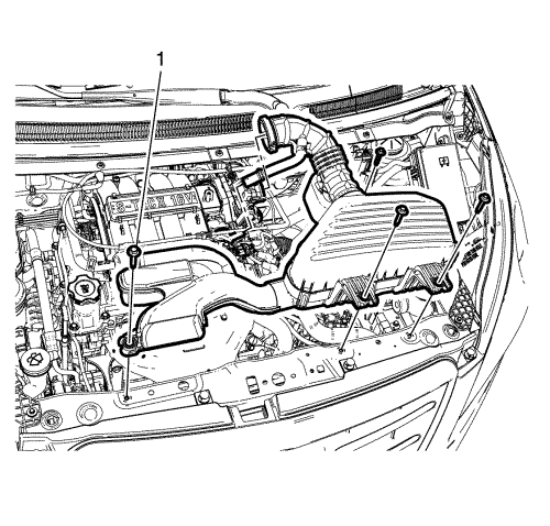
- Install the air cleaner assembly and tighten the 4 air cleaner assembly bolts (1) to 6 N·m (53 lb in).
- Install the hoses to throttle body assembly.
- Tighten the clamp (2).
- Connect intake air temperature sensor connector (1).
- Install the plenum lower panel. Refer to Plenum Lower Panel Replacement .
- Install the bonnet. Refer to Bonnet Replacement .
- Connect the engine wiring harness (1) in the leg room.
- Adjust the clutch. Refer to Clutch Assembly Adjustment .
- Evacuate and recharge the A/C system. Refer to Refrigerant Recovery and Recharging .
- Check the transmission fluid, if necessary. Refer to Transmission Fluid Level Inspection .
- Refill the cooling system. Refer to Cooling System Draining and Filling .
- Check the oil level and fill NEW engine oil up, if necessary.
- Connect the battery negative cable. Refer to Battery Negative Cable Disconnection and Connection .
- Close the bonnet.


